1
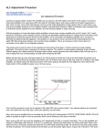
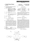
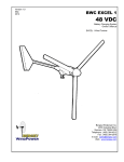
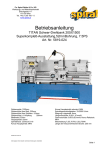
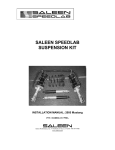
TWG-ⅤA Roll Grooving Machine
User’s Manual
Familiar yourself with this Manual prior to operation.
Tuwei Construction Equipment Manufacturing Co., Ltd,
People’s Republic of China
Table of Contents
Ⅰ
Major
applications
and
scope···················································································2
Ⅱ
Technological
Parameters······················································································2
Ⅲ
Major
Parts···············································································································
3
Ⅳ
Driving
System··········································································································3
1
Ⅴ
Electric
System·········································································································4
Ⅵ
Operations
and
Adjustments····················································································4
Ⅶ
Precautions·······································································································
·······11
Ⅷ
Troubleshooting·································································································
·······12
Ⅸ
The
assembly
drawing
of
2
grooving
machine
and
parts
form····································14
I. Major applications and scope
This machine is applicable for forming circular channel at the end of seamless steel
tubing, galvanized pipes, plastic-lining pipes and stainless steel pipes
etc, to facilitate the mounting of circular pipe clamps. It’s an ideal tool
for construction industry and pipeline construction sectors.
II.
Technological Parameters
Max. diameter allowed for pipes to be channeled………………………………219mm
Min. diameter allowed for pipes to be channeled…………………………………57mm
Max. wall thickness allowed for pipes to be channeled……………………………6mm
Max. working pressure………………………………………………………………4000kg
Max. oil cylinder pressure ……………………………………………………………40Mpa
Capacity of oil tank……………………………………………………………………76ml
3
Speed …………………………………………………………………………………23 rpm
Electric motor ……………………………………three phase/700W,single phase/750W
Overall dimensions (W×D×H)………………………………1020mm×560mm×630mm
Net weight………………………………………………………………………………70kg
III.
Major parts
Fig.1
TWG-ⅤA Roll Grooving Machine
1. limit fastening nut,
2.limit nut,
3.relief
valve, 4.oil cylinder, 5.slide, 6.pinch roller
holder, 7.pinch roller shaft, 8.pinch roller,
9.knurl shaft, 10.unit head, 11.machine rack,
12.handle seat, 13.handle, 14.adjust bolt screw,
Fig.1
Fig. 1
15.safety cover,16.reduction motor, 17.switch
4
single phase motor
Fig. 2
IV.
Driving System
The major moving unit of this machine consists of
a rotating spindle directly driven by a reduction
motor,resulting in a reduced loss of mechanic power.
The feeding movement is realized by manual hydraulic system.
Fig.2
V. Electric System
Refer to Fig.2 or Fig.3 for the Electric Circuit Diagram
of this Grooving Machine. Consists of an electric motor,
a clockwise/stop/ anti-clockwise switch and cables.
Turning clockwise, anticlockwise and stop are controlled
by the switch. An electric motor is the only load. The
power supply shall agree with the requirements of motor,
Sound earthing of ground wire (black) is required prior to
starting the machine.
three phase motor
Fig. 3
VI. Operation and Adjustment
1. Let the machine run idle to check whether
it’s normal.
2. Place steel pipe on the knurl shaft and
5
handle
bracket.The bracket shall be placed at a
position equal to 3/4 of the length of whole
pipe(See Fig.4).Turn machine rack’s handle,
adjust the pipe or the other of bracket is lower 1-2
degree.Start the machine whether the pipe
Fig.5
Fig. 4
Fig.
Fig.6 5
will move outward.If it moves,you should adjust the bracket left and right opsition till
don’t move outward.After test exactly,let four feet of the machine and three feet of
bracket fixed(See Fig.5).
6
3. Tighten the relief valve of oil cylinder,turn the handle,make the pinch roller holder
toward down.Start the machine,make pinch roller turn down the pipe gradually.Turn the
handle at a faster speed at the beginning to form the initial channel and later on you
shall turn slowly.(See Fig.5)
Fig.7
Fig.9
Fig.8
Fig 6
4.
Limit and depth adjustment of channel. First loosen the limit nut(See Fig.7- Fig.8).
Measure and cut the first channel followed by fastening of limit nut. For the following
channels, it means the desired chan-neling depth has been attained when the force to
7
apply to the handle increases, and you shall stop turning the handle to let the pinch
roller roll at the original position for 1-2 turns before opening the relief valve (See Fig.
6 No.42) to allow the pinch roller leave the pipe. The pinch roller holder will return to its
highest position auto-matically. The above procedure shall occur while the machine is
kept on.
5. Remove the filler plug to add hydraulic oil. (loosen the relief valve,remove all the dusts
near the filler aperture).Unscrew the discharge screw (See Fig.6 No.8) before
discharging all the dirt used oil(See Fig. 6).
6.If you want to remove the whole oil cylinder from the unit head, you shall press the slide
and move it downward to the lower position,loosen the 2 fasten screws of piston fasten
ring and the 8 socket head screws of pump seat(See Fig. 10- Fig. 11 )
8
Fig.10
Fig.11
Fig.12
7. If you want to remove the whole pinch roller holder,loosen the 2 fasten screws of piston
fasten ring(See Fig. 10).,then loosen the 8 socket head screws of two guide rail
bars(See Fig. 12).
8. For the replacement of pinch roller, you shall return the pinch roller holder to the highest
position and remove the screws of pinch roller holder’s side, before pulling out the
roller shaft while holding the roller with your hand(See Fig. 13- Fig. 14 ). For the
relocating of pinch roller,you shall loosen 2 bolts on the slide and turn the adjustment
bolts to move the pinch roller forward/backward. Refer to Fig.9 for specific location
requirements. Followed by tightening the 2 bolts(See Fig. 15- Fig. 16 ).
Fig.13
Fig.14
Fig.15
Fig.16
9. When replace the pinch rollers,please also replace the matched knurl wheels(Table
9
1).When process the pipes under D168mm,You can use roller shaft directly(see
Fig.17), When process the pipes upon D219mm,please install the knurl wheel on the
roller shaft (See Fig. 17 -Fig. 19).
10. In case of steel pipes of large diameter(above of Φ89 mm)to be channeled,the pipe
may swing violently in the process of channeling due to irregularity,and a poor
channeling or even failure may be resulted.To solve this problem,we particularly supply
an optional jockey roller(see Fig.20) which can be moved to touch the steel pipe by
turning the handwheel and screw down fasten screws of jockey roller for the purpose
of reduced vibration.
Fig.17
Fig.18
10
Fig.19
Fig.22
Fig.20
Fig.21
Table 1 (See Fig.22)
Diameter of
Groove Bottom
Max.
Min. (mm)
Nominal
Pipe
Dia.(inch)
Actual Pipe
Dia.(mm)
2″
57
15.88
8.74
1.65
53.85
53.47
2″
60
15.88
8.74
1.65
57.15
56.77
2-1/2″
76
15.88
8.74
1.98
72.26
71.80
3″
89
15.88
8.74
1.98
84.94
84.48
4″
108
15.88
8.74
2.11
103.73
103.22
4″
114
15.88
8.74
2.11
110.08
109.57
5″
133
15.88
8.74
2.11
129.13
128.62
5″
140
15.88
8.74
2.11
135.48
134.97
A±0.5
B±0.5
C±0.5
(mm)
(mm)
(mm)
(mm)
11
6″
159
15.88
8.74
2.16
154.50
153.94
6″
165
15.88
8.74
2.16
160.78
160.22
6″
168
15.88
8.74
2.16
163.96
163.40
8″
219
19.05
11.91
2.34
214.10
213.76
·Ⅶ. Precautions
1. You are required to familiar yourself with structure of machine, functions of various
handles as well as the driving and lubrication system through reading the Manual prior
to operation.
2. Before starting the machine, you shall add oil as instructed in the Manual,check
whether the hydraulic cylinder has been filled with oil (20# oil in the summer and 10 #
oil in the winter).
3. The grease nozzle in front of the pinch roller shaft shall be lubricated each shift.
Remove all the dusts near the filler aperture before adding oil.
4. Earthing and fuse are required in the circuit.The motor shall be properly wired.Never
run the machine overload.
5. Any steel pipe shall have smooth ends and surface by grinding before being channeled.
Otherwise bur may occur to the pipe, the machine’s service life will be significantly
12
shortened, and leakage may occur to the pipeline.
6. During servicing of grooving machine,lubrication grease shall be adhered to needle
bearing before re-assembly.
7.In case of steel pipes of large diameter to be channeled,fix the four feet of
machine and the three feet of bracket,to the ground by screws.
·Ⅷ.
Troubleshooting
Problem
Causes
1.Insufficient hydraulic
oil.
2. Dirt oil blocks the
hole.
Solutions
Add hydraulic oil
No pressure in the oil
Replace the hydraulic oil,clean the
cylinder. No action
oil net.
resulted from turning the
Remove the screws and spring.
handle.
3. Leakage occurs to the
Knock the small steel balls lightly to
check valve
force out the air-tight surface.
1. Dirt oil blocks the
Replace the hydraulic oil
The piston will move
hole.
13
forward when the handle
Remove the screws and spring.
2. Leakage occurs to the
is forced downward, but
Knock the small steel balls lightly to
check valve
it will return when the
force out the air-tight surface.
handle is released.
3. Leakage occurs to
other position
Insufficient oil cylinder
pressure
The pipe escapes
The spring of safety
valve breaks down
1. Improper direction
and height of bracket.
Trace the problem and correct.
Replace the safety valve.
Vary the direction and height of
bracket.
Toggle
the
2. Improper direction of clock-wise/anti-clockwise switch to
steel pipe
change the rotation direction of
spindle
3. Rough end face of
Grind the end face.
steel pipe
14
·Ⅸ.The assembly drawing of machine and parts form
15
Fig.23
1. TWG-ⅥA Roll grooving machine component and parts form (Fig.23)
S/N
1
2
3
4
5
6
7
8
9
10
11
Code name
GB/T70.1-2000
TWG5-03-002
TWG5-03-003
GB5781-2000
TWG5-03-010
GB/T70.1-2000
TWG-03-005
GB79-2000
TWG5-03-006
JB7940.1-95
Name
Screw M6×16
Piston fixed ring
screw
Hexagonal bolt C level M8×35
Guide rail bar
Screw M8×20
Pinch roller holder
Fasten screw M8×20
Pinch roller shaft
Oil cup M10×1
Plane bearing 889105
16
Qty
2
1
2
2
2
12
1
1
1
1
1
Material
45#
45#
45#
ZG200-400
20CrMnTi
12
13
14
15
16
17
TWG5-03-009
GB/T70.1-2000
TWG5-03-008
TWG5-03-001
GB79.1-2002
TWG5-03-004
Adjust screw
Screw M6×15
Bolt fixed ring
slide
Washer Alevel ¢8
Feather key
17
1
4
1
1
14
1
45#
45#
ZG200-400
45#
S/N
18
19
20
21
22
23
24
25
26
27
28
29
30
31
32
33
34
35
Code name
GB70.1-2000
TWG5-03-007
TWG5-01-002
GB3452.1-92
TWG5-01-006
TWG5-01-003
GB279-94
TWG5-01-004
TWG5-02-00
GB93-87
TWG5-06-00
GB/T70.1-2000
GB/T70.1-2000
GB93-87
GB97.1-2002
TWG5-01-001
TWG5-04-00
Name
Screw M5×12
Pinch roller
Needle bearing RNA6904
Knurl shaft
O-type seal ring ¢71×1.9
Dustproof ring
Fore cover
Cine roller bearing 32009
bushing
Oil pulley assembly
Spring washer ¢8
Jockey pulley assembly
Screw M8×25
Screw M10×30
Spring washer ¢10
Washer A level ¢10
Unit head
Machine rack
18
Qty
3
1
1
1
2
1
1
2
1
1
12
1
8
4
8
8
1
1
Material
40Cr
20CrMnTi
ZG200-400
45#
Subassembly
Subassembly
HT200
Subassembly
S/N
36
37
38
39
40
41
42
43
44
45
46
47
48
49
50
51
52
53
Code name
TWG5-01-005(2)
GB/T70.1-2000
GB815-88
GB858-88
GB/T70.1-2000
TWG5-01-007
TWG-01-008
GB67-2000
GB93-87
Name
Rear cover
Screw M10×25
Round nut M40X1.5
Stop washer ¢40
Screw M10×45
Safety cover
750W reduction motor
Nameplate
Slotting screw M5×8
Spring washer ¢5
Switch
19
Qty
Material
1
HT200
4
2
1
4
1
1
1
4
4
1
Sheet=1.2
Fig.24
Fig.25
20
2. Oil pump parts form (Fig.24)
S/N
1
2
3
4
5
6
7
8
9
10
11
12
13
14
15
16
17
Code name
TWG5-02-006
TWG5-02-004
TWG5-02-002
GB3452.1-92
GB3452.1-92
TWG5-02-003
GB3452.1-92
GB/T70.1-2000
TWG2-02-026
TWG2-02-025
TWG2-02-023
GB3452.1-92
TWG2-02-024
GB/T91-2000
TWG2-02-009
TWG5-02-008
TWG5-02-007
Name
Spring
Piston cylinder sleeve
Oil box
O-type seal ¢63×3.55
O-type seal ¢31×3.55
Pump seat
O-type seal ¢6×1.8
Screw M6×10
Conical valve
Flooding spring
Safety valve screw
O-type seal ¢11×2.2
Safety valve bulkhead
Split pin ¢2.5
Connection plate
Kimit fastening nut
Limit nut
21
Qty
1
1
1
2
1
1
1
1
1
1
1
1
1
2
1
1
1
Material
65Mn
¢50×5 oil pipe
45#
45#
45#
S/N
18
19
20
21
22
23
24
25
26
27
28
29
30
31
32
33
34
35
36
Code name
JB/ZQ4446-1997
GB3452.1-92
GB/T70.1-2000
TWG5-02-001
GB3452.1-92
TWG5-02-005
GB/T882-1986
TWG5-02-010
GB/T70.1-2000
TWG2-02-006
GB3452.1-92
TWG5-02-009
TWG2-02-001
GB308-89
Name
Dustproof ring D22×d14
Plug 2G1/8〃
O-type seal ¢8×1.8
Screw M6×20
Pump body
Y-type seal d14
O-type seal ¢50×3.55
Y-type seal D40
Bin piston rod
Pin shaft ¢6×25
Small piston rod
Washer (1)
Screw M6×35
Handle seat
O-type seal ¢10×2.4
Cylinder sleeve
Seal 18×1.4
Drink oil spring
Steel ball 5
22
Qty
1
1
2
1
1
1
1
1
1
2
1
1
1
1
2
1
1
1
1
Material
Gather ammonia grease
45#
Rubbefr
45#
Gather ammonia grease
Gather ammonia grease
45#
45#
Tetlin
FI rubber
45#
Purple copper
S/N
37
38
39
40
41
42
43
44
45
46
47
48
49
50
51
52
53
54
Code name
TWG2-02-022
TWG2-02-019(1)
GB3452.1-92
TWG2-02-019(3)
TWG2-02-0025
GB3452.1-92
TWG2-02-005
TWG2-02-008
TWG2-02-003
GB308-89
TWG2-02-004
GB3452.1-92
GB308-89
TWG2-02-019(2)
Name
Suction pipe
Strainer
Relife valve nut
O-type seal ¢11×1.9
Washer(2)
Relief valve handle
Screw
O-type seal ¢11×2.4
Handle
Handle sleeve
Delivery spring
Steel ball 8
Filler plug
O-type seal ¢12×1.9
Steel ball 6
Cipper washer(2)
Relief valve
Spring pin ¢3
23
Qty
1
1
1
1
1
1
1
1
1
1
1
1
1
1
1
1
1
1
Material
45#
45#
Buna-N rubber
Tefllon
Aluminium alloy
Buna-N rubber
Buna-N rubber
45#
3. Jockey pulley parts form (Fig.25)
S/N
1
2
3
4
5
6
7
8
9
10
11
12
13
14
15
16
17
Code name
GB75-85
TWG5-06-007
TWG5-06-006
TWG5-06-003
GB41-2000
GB/T91-2000
GB78-2000
TWG5-06-001
TWG5-06-004
TWG5-06-005
TWG5-06-002
GB117-2000
Name
Handwheel
Slotting fasten screw M4×8
Stop block
Fasten nut
Jockey pulley shaft
Jockey pulley
Nut C level M12
Split pin ¢2.5
Fasten screw M6×8
Adjust rod
End cover
Jockey pulley body
Guiding axis
Cone pin
24
Qty
1
1
1
1
1
1
1
2
1
1
1
1
1
1
Material
Subassembly
45#
45#
45#
Subassembly
45#
45#
QT450-10
45#
Fig.26
25
4. Bracket parts form (Fig.26)
S/N
1
2
3
4
5
6
7
8
9
10
11
12
13
14
15
16
17
Code name
GB276-94
TWG2-05-006
GB5781-2000
TWG2-05-002
TWG2-05-004
TWG2-05-003
TWG5-05-01
GB819.1-2000
Name
Bearing 6205
Bearing retainer ring
Hexagonal bolt M10×30
Thread rod
Adjust nut
Bracket handle
Bracket base
Screw M8×14
26
Qty
Material
4
8
4
1
1
HT200
2
45#
1
Subassebly
1
1. Our company reserves the authority of changing the products and specification, if any
alteration we don't inform specially.
2. Difference between the picture and the object, please be subject to the object.
Tuwei Construction Equipment Manufacturing Co., Ltd,
Add: No.31 Kangzhuang Road,Western industry zone,Huangyan,Taizhou, Zhejiang,China
Tel:0086-576-84715288 84715290
Fax:0086-576-84715289
Postal code: 318020 Http://www.cntuwei.com E-mail: [email protected]
27