1
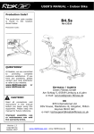
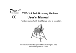
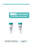
Kaifeng Kaide Flow Instrument Co.,Ltd
No2. Indusrtial Road, Huanglong Industrial Park, Kaifeng County, Henan, China
Tel: 86-378-3212788 Fax: 86-378-6682432
VORTEX FLOWMETER
USER MANUAL
1
CONTENTS
1. Introduction ········································································································3
2. Measuring principle
principle·····························································································3
3. Technical parameters
parameters···························································································3
4. Lectotype instruction
instruction··························································································· 4
4.1 Selection of nominal diameter:···············································································4
4.2 Confirm the suitable configuration········································································· 5
4.3 The calculation of transducer pressure loss································································5
4.4 Liquid phase guaranteed·························································································6
4.5 Example of diameter selection·················································································6
5. Installation method and steps
steps············································································· 6
5.1 Choose the right installation site·············································································· 6
5.2 Installation notes··································································································· 8
5.3 The outline dimensional drawing of transducer for reference when mounting················ 8
5.4 The selection of pressure and temperature measuring point········································· 9
6. Connecting of signal wire
wire···················································································· 10
7. Debugging of transducer
transducer····················································································· 11
8. Trouble shooting
shooting···································································································12
9. Intelligent flow totalizer
totalizer······················································································ 12
10. Wireless remote flow monitoring system
system·························································· 13
11. Back-up power supply
supply························································································ 13
12. Lectotype Codes
Codes·································································································· 14
13. Appendix
Appendix············································································································· 14
The manual of compact local LCD vortex flowmeter
flowmeter···········································17
2
1. Introduction
Stress type vortex flowmeter is a kind of velocity type flowmeter, based on Karman vortex
street theory, adopt piezoelectric crystal to measure the vortex frequency produced by fluid
flowing through the triangular prism in the pipeline, then the flow value can be measured. Vortex
flowmeter is widely applied in industries like petroleum, chemical, light industry, power supply,
heat supply, etc..
It has the characteristics as follow:
High accuracy, wide range;
Wide medium application, able to measure liquid,
gas and steam;
High operating temperature, the temperature of
fluid up to 350℃;
No moving parts, no abrasion, high reliability;
Stainless steel shell, corrosion resisting.
2. Measuring principle:
When the fluid flows through vortex generator(the triangular prism) in the pipeline, as partial
flowrate go up, a vortex pattern appears(as shown in fig.1), the vortex alternatively appears as two
columns, it is called Karman Vortices. The vortex alternatively segregates, a fluctuating force is
produced in the wake flow behind the prism, the detecting probe installed behind(or in) the prism
is affected by this tiny fluctuating force and the piezoelectric crystal parts buried in the probe is
affected by the alternative stress, then a alternating charge signal is generated. The detector
amplifier transforms, amplifies, wave filtering and signal reshaping this signal, then outputs a
voltage(or current) pulse signal with a frequency same as that of vortex shedding frequency or
outputs an analog current signal which has a proportion with vortex shedding frequency. Each
pulse or every certain current the meter outputs stands for certain volume of measured fluid. The
total pulse or the integration of analog current in a certain period of time stands for the total flow
of the fluid in it.
The discharge rate of Karman Vortex Street is related to the width of triangular prism and the
flowrate of the fluid, but have nothing to do with parameters like fluid temperature and pressure. It
can be expressed by the formula as below:
f=StV/d
Thereinto:
f----the frequency of Karman Vortex Shedding
St----Strouhal Number
V----velocity
d----width of the triangular prism
Strouhal number(St) is a important parameter of vortex flowmeter, it is only related to
Reynolds number(Re). Only if Re is between 2 × 10⁴ and 7 × 10⁶, keeps being a
constant(0.17~0.18). In this case, the flowrate can be measured through measuring vortex
frequency signal and the flow can be worked out through the flowrate of the fluid.
3. Technical parameters:
3
Nominal diameter: DN15, DN20, DN25, DN32, DN40, DN50, DN65, DN80, DN100,
DN125, DN150, DN200, DN250, DN300, DN350, DN400, DN450, DN500;
Application: gas(air, oxygen, nitrogen, coal gas, natural gas, chemical gas, etc.), liquid(water,
high temperature water, oil, beverage, chemical liquid, etc.), steam(saturated steam, superheated
steam);
Fluid temperature: -40℃~+280℃, -40℃~+350℃;
Nominal pressure: ≤1.6MPa, ≤2.5MPa, ≤4MPa;
Accuracy: ±0.5% for liquid and gas, ±1.0% for steam;
Flowrate range: 0.27~9m/s for liquid, 3~80m/s for gas, 3~90m/s for steam;
Measuring range: refer to table2;
Signal output:
Voltage pulse: low level≤1V, high level≥6V, pulse width 0.4ms, load resistance>150Ω;
Standard current: 4~20mA, conversion accuracy ± 0.5% full scale value, load resistance
24V~500 Ω , local LCD display: 5-bit display of instantaneous flow(m3/h, kg/h, t/h),
conversion accuracy±0.1%; 5-bit display of cumulative flow(m3,kg,t), conversion accuracy
±0.1%;
Power supply:
Voltage pulse output: +12VDC;
4~20mA output: +24VDC;
Local LCD display: 3.6V 5# lithium battery powered, have a service life over 2 years.
Ambient temperature:
Voltage pulse output: -30℃~+65℃;
4~20mA output: -10℃~+55℃;
Local LCD display: -25℃~+55℃;
Body material: 1Cr18Ni9Ti(others refer to contract)
4. Lectotype instruction
4.1 Selection of nominal diameter:
When the diameter of transducer is different, the measuring range is different. And the
measuring range of transducer with a certain diameter varies with the fluid difference, operating
temperature and pressure, etc.
4.1.1 For saturated steam, when one of operating temperature and pressure, a rough flow
range are known, the transducer diameter can be confirmed through table look-up(refer to table 1);
For superheated steam, when the operating temperature and pressure are known, look up table 2 to
confirm density, along with flow range, look up table 1 to confirm the transducer diameter.(Note:
The pressure values in table 1 are absolute pressure, which is the sum of pipeline pressure and
atmospheric pressure.)
4.1.2 For gas and liquid, when the medium conditions are inconsistent with that in the
tables or other medium applied, the measurement of flowmeter will be affected by medium
density and viscosity. The flow range is needed to be confirmed in advance, then look up table 3 to
confirm the transducer diameter.
In this case, flow range can be confirmed in the following way:
4
A. lower limit flow value:
1 According to the lower limit flow Qmin , fiducial medium density ρ 0(the density of gas
○
medium is 1.293Kg/m3 and liquid medium 1000Kg/m3) and the measuring medium density ρ
given in table 1, the lower limit flow Qminρ can be worked out through the formula given below:
Qminρ= Qmin ×(ρ0/ρ)1/2(m3/h)
2 According to kinematic viscosity of medium V, the lower limit flow Qmin can be worked
○
out through the formula given below:
QminV= 6VD×104(m3/h)
Thereinto: D---- pipe inside diameter(mm)
Compare Qmin ρ and QminV, choose the higher value as the lower limit flow value of certain
type of flowmeter.
B. upper limit flow value:
Generally, the upper limit flow value of liquid is 9m/s, gas 80m/s and steam 90m/s.
4.2 Confirm the suitable configuration
A. Choose the right type: remote transmission or local display;
B. For remote transmission type, if the fluid is saturated steam, choose automatic temperature
compensation density; if the fluid is superheated steam, choose temperature and pressure
compensation density; for other medium, whether compensation is needed or not depend on the
practical situation; if the accuracy requirement is low and temperature or pressure is constant,
choose fixed pressure or fixed temperature compensation, fixed density compensation is also
suitable;
C. For intelligent flow totalizer, if display requirement is only for flow, pressure, temperature,
etc., choose nixie tube display or LCD intelligent totalizer; if memory function is needed to
chasing historical data, choose intelligent flow totalizer paperless recorder;
D. Whichever type of intelligent flow totalizer is chosen, a RS485 or RS232 communication
interface should be considered to be installed;
E. Whichever type of intelligent flow totalizer is chosen, a back-up power should be
considered to be deployed in order to keep the instrument properly functioning when there is a
power failure(the working life varies with different configuration, normally 24~48 hours or
above);
F. When choosing intelligent flow totalizer, an instrument box should be considered to be
provided to put the intelligent flow totalizer in to avoid the set parameter being randomly adjusted;
G. When choosing remote transmission type, a wireless remote flow monitoring system
should be considered to be applied to realize real-time monitoring and management of flow in
each pipeline;
H. If the measured medium is explosive and flammable material or there is explosive and
flammable gas in the measuring environment, explosion-proof transducer and measuring system
should be applied.
4.3 The calculation of transducer pressure loss
After confirming the transducer diameter, the transducer pressure loss can be worked out to
figure out whether transducer has a impact on process pipeline.
5
The formula is as below:
P≤1.2ρV2
Thereinto: ΔP---- transducer pressure loss(Pa)
ρ---- fluid density(Kg/m3)
V ---- the average velocity of fluid
4.4 Liquid phase guaranteed
In order to avoid vaporization or gas etching, the fluid pressure of the flowmeter should meet
the requirement of the following formula:
P>2.6Δp+1.25Ps
Thereinto: Ps---- the saturated steam pressure of the liquid, which correspond with certain
temperature(KPa)
P ---- pressure of the fluid(Pa)
4.5 Example of diameter selection
Eg.1: The inside diameter of process pipeline is DN100, medium is saturated steam, steam
consumption is around 0.5t/h~3t/h, instrument pressure is 0.4MPa, please confirm the proper
instrument diameter.
Solution: From instrument pressure 0.4MPa, we know the absolute pressure is 0.5MPa, look
up table 2 to find out the temperature is 152℃. As flow range of DN100 is 0.4~3.5t/h, totally meet
the operating requirement, a vortex flow transducer with a diameter of DN100 should be chosen
here. If the steam consumption is around 0.3t/h~2t/h, choose the ones with a diameter of DN80,
the process pipeline diameter should be deducted from DN100 to DN80.
Eg.2: The inside diameter of process pipeline is DN100, medium is superheated steam, steam
consumption is around 0.5t/h~2.8t/h, instrument pressure is 0.4MPa, temperature is 220℃, please
confirm the proper instrument diameter.
Solution: Based on instrument pressure(0.5MPa) and temperature(220℃), look up table 3 to
find out the density:2.66. Then look up table 2 to get the flow range: 0.4~3.5t/h, totally meet the
operating requirement, a vortex flow transducer with a diameter of DN100 should be chosen here.
If the steam consumption is around 0.3t/h~2t/h, choose the ones with a diameter of DN80, pipe
reduction would be needed here.
5. Installation method and steps
5.1 Choose the right installation site:
When choosing installation site, pay attention to the following points:
A. The installation site should be in the location with no or little vibration, the vibration
acceleration should be no more than 2g, if exceeded, adopt vibration reducing measures;
B. There should be enough straight pipe for both upstream and downstream(refer to fig.2);
C. Service valve should be installed at the upstream of transducer and regulating valve
downstream;
D. Choose the most convenient location for installation and maintenace as possible;
E. Dry location is more suitable;
F. Transducer can be installed at both the horizontal and vertical pipelines. When being
installed at the vertical pipeline, fluid(liquid) must flows from bottom to top;
6
G. Transducer is better installed indoor, pay attention to water proof if it must be installed
outdoor, cable outside the amplifier box should be bowing;
H. Transducer should be kept away from electrical noise, such as high power inverter, high
power transformer, electromotor and high power wireless transceiver.
The requirement of straight pipe:
1. Converging pipe
The length of straight pipe should be ≥ 15D for upstream and ≥ 5D for downstream if
converging pipe(>150) is installed in the upstream of transducer installation site;
upstream
downstream
2. Diverging pipe
The length of straight pipe should be ≥ 18D for upstream and ≥ 5D for downstream if
diverging pipe(>150) is installed in the upstream of transducer installation site;
3. 900 elbow or T joint
The length of straight pipe should be ≥20D for upstream and ≥5D for downstream if a 900
elbow or T joint is installed in the upstream of transducer installation site;
4. Two 900 elbow are (on the same plane)
The length of straight pipe should be ≥25D for upstream and ≥5D for downstream if two
0
90 elbow are on the same plane in upstream;
5. Two 900 elbow are (on different plane)
The length of straight pipe should be ≥40D for upstream and ≥5D for downstream if two
0
90 elbow are on different plane in upstream;
7
6. Control valve
Flow or pressure control valve should be installed at least 5D away from the meter, if the
valves must be installed in upstream, the length of straight pipe should be ≥ 50D for upstream
and ≥5D for downstream;
7. Rectifier
The length of straight pipe should be ≥ 8D for upstream and ≥ 5D for downstream if a
rectifier is installed in upstream;
5.2 Installation notes
A. When welding flange with straight pipe, demount transducer;
B. When mounting transducer, make sure the flow direction arrow on the shell is in
accordance with the flow direction in the pipeline;
C. After welding flange, clean the pipeline, make sure there are no impurities like welding
slag in the pipeline;
D. Before mounting transducer, make sure a sealing washer is put in the groove of the flange.
5.3 The outline dimensional drawing of transducer(fig.3 and table 5),for reference when mounting.
8
Table 5: The outline dimension of general instrument
DN
B0
C0
D0
H0
matched with
seamless steel tube
15
65
101
125
422
φ18×1.5
20
65
101
125
422
φ26×3
25
65
101
125
422
φ32×3.5
32
70
110
145
427
φ38×4
40
75
115
145
427
φ45×2.5
50
75
117
160
435
φ57×35
65
75
123
180
445
φ73×4
80
84
132
296
450
φ89×4.5
100
90
138
230
474
φ108×4
125
100
152
245
482
φ133×4.5
150
120
174
280
499
φ159×4.5
200
150
206
336
526
φ219×9
250
160
216
406
563
φ273×10
300
170
228
460
590
φ325×12
5.4 When transducer, along with pressure transmitter and temperature transmitter, constitutes a
measuring system, the selection of pressure and temperature measuring point refer to the
following fig..
5.4.1 The installation of pressure transmitter
A. Open a pressure transmitting hole(around φ12) at the certain spot on the pipe given in
fig.6;
B. Weld pressure transmitting block to the pressure transmitting hole, avoid leakage;
C. Mount needle valve;
9
D. Mount run;
E. Close the needle valve, inject cold water into the run;
F. Mount pressure transmitter;
5.4.2 The installation of platinum thermal resistor
A. Open a small hole at the certain spot on the pipe given in fig.6, the diameter of the hole
should be slightly greater than the outer diameter of platinum thermal resistor(around φ40);
B. Weld the platinum resistance base to the hole, ensure the bottom end of the base is in the
centreline of pipe.
The method of installing pressure transmitter and platinum resistance to horizontal pipe
The method of installing pressure transmitter and platinum resistance to vertical pipe
6. Connecting of signal wire
8BVPV3 × 0.5 signal transmitting wire is provided along with transducer, therein: the red
wire is the positive power supply, the black wire is the negative power supply, others are
frequency signals. The wire mode of transducer, pressure transmitter and platinum thermal resistor
is as shown in fig.7. The shielded cable should be as far away from highfield as possible and being
laid with highline is strongly prohibited. The shielded cable should be as short as possible and
avoid being rolled, so that the distributed capacitance can be reduced. The cable length is better
less than 500m(for voltage pulse type), please consult with us if you need more.
10
Fig.7: The wire mode of transducer, pressure transmitter and platinum thermal resistor
7. Debugging of transducer
Generally, there is no need of zero setting as the transducer is often well adjusted before
leaving factory. However, when the ambient condition changes and the instrument functions
11
abnormally, reset zero point as described below:
Power on the transducer, fill the process pipeline with medium, close the valve in
downstream of transducer(close the one in upstream instead if it is unable to be closed),
widdershins adjust the potentiometer SF(near the terminal) to the end, at this moment, there are
signals of disturbing pulse output(for 4~20mA output type, use a multimeter to check if there is
pulse output from the first circuit board, if not, adjust the potentiometer pointer to R to make the
signal output 4mA, R stands for the potentiometer being adjust to the full scale value), then slowly
deasil adjust SF till there is no output. Open the valve, the instrument would normally function.
8. Trouble shooting
Malfunction 1: There is flow in the pipeline, yet no output from transducer or no display of
intelligent flow totalizer:
A. Make sure there is flow in the pipeline and the flow value is higher than the lower limit of
measurable flow;
B. Check if there are any misconnections or brokens of wire: the basic method is to check the
wire or beat the pipeline with a hammer or stick, adjust the totalizer to display frequency to see if
there is frequency displayed, if there is, then no wire misconnection; if not, check the wire;
C. Check the amplifier: remove the probe wire from amplify board to see if there is output
from transducer or 50Hz frequency display of intelligent flow totalizer, if not, change the amplify
board, if there is, then the amplifier is well functioning;
D. Check the transducer: remove the two lead wires of transducer from amplify board, use a
multimeter to measure the resistance between the two lead wires and the respective resistance of
them, both of which should be more than 2MΩ, otherwise, the transducer should be replaced;
E. If there is nothing wrong with transducer, check if the pressure transmitter and platinum
thermal resistor are damaged. If the display of pressure and temperature of the intelligent flow
totalizer is normal, then the totlizer is probably damaged.
Malfunction 2: There is no flow in the pipeline, yet there is output from transducer and
display of totalizer:
A. Check if the vibration of the transducer installation site is overlarge, if it is, a shock strut
should be considered to be mounted;
B. Bad grounding of instrument brings interference;
C. Eliminate it from the setting of small signal elimination;
D. Please contact our technical department to solve other kinds of malfunctions.
Malfunction 3: The flow in pipeline is normal, yet the display of instrument shows a big
wave of flow value:
A. Wrong or inappropriate installation;
B. Unsuitable trigger sensitivity or gain adjustment of amplifier, adjust the dial switch.
9. Intelligent flow totalizer
According to customer's needs, we provid many kinds of flow totalizer along with transducer,
such as nixie tube display intelligent flow totalizer, LCD intelligent flow totalizer, intelligent flow
totalizer paperless recorder, etc., back-up power supply and wall-mounted instrument box are also
available for special need.
The main features of the totalizers are as follow:
12
� Measuring accuracy: better than ±0.2% for analog quantity and better than ±0.2% for
frequency quantity;
� Flow signal can be frequency or standard current;
� Able to display cumulative flow, instantaneous flow, differential pressure, frequency,
density, pressure, temperature, the current time andthe duration of power failure;
� Realize automatic temperature compensation density, automatic pressure compensation
density and temperature and pressure compensation density;
� RS485 or RS232 communication interface are available, possess lightning protection
function;
� Able to work with micro-dot-matrix printer, randomly or timely print cumulative flow,
instantaneous flow, pressure, temperature, current time and the duration of power failure, the
intelligent flow totalizer paperless recorder can print the historical data and curve of specified
period of time;
� After a simple programming, it is able to do heat calculation and measure the thermal
difference of the measured medium;
� Possess automatic recovery function: apart from watch-dog software, there are
watch-dog, power-on and brown-out reset system hardware deployed, once there is a system
error or an accidental death, these functions can ensure the instrument forcibly resume;
� Possess power failure protection function: the operational results and the data set by
customer in the totalizer would not lose when there is a power failure, the saving time can be
as long as ten years;
� Back-up power supply is available, automatically go into back-up power supply when
there is a power failure to make sure the instrument normally operating.
10. Wireless remote flow monitoring system
Wireless remote flow monitoring system is base on wireless private network, adopt many
advanced technologies, remotely real-time gather the data of parameters like cumulative flow,
instantaneous flow, temperature, pressure of heatpipeline users terminal, then transmit them to the
supervising centre though wireless communication and make record, then the daily management is
completed. Meanwhile, according to the measured parameters, leakage and the cheating in gas
using can be spotted in time, realize the chasing of historical metrological data so that deputies
about gas using can be avoided.
This system has the features as follow:
� Electric map of heatpipeline system;
� Monitor the parameters like cumulative flow, instantaneous flow, temperature, pressure,
gas using period and instrument power on hours of all users;
� Able to provide the real time parameter curve of each user;
� Able to provide the annual, monthly and daily cumulative flow curve of all and each of
users;
� Able to provide the annual, monthly, daily or any period of time report forms of all and
each of users;
11. Back-up power supply
Back-up power supply eliminates the defect of not able to properly function when there is a
13
power failure. When normally functioning, the back-up power supply is in charging status or
holding status(automatically turn into holding status after fully charged); when there is a power
failure, the back-up power supply automatically turn into supply status. It is able to make the
instrument continuously work more than 48 hours.
12. Lectotype Codes
The model of stress vortex flow transducer can be stated as:
LUGB-X
X
XXX - X
1
2
3
4
○
○
○
○
1 stands for the way of jointing
○
Connecting method
Flange connection
Flange clamped
Inserted
Mark no.
1
2
3
Remarks: The mark no. of inserted vortex nominal diameter is its drift diameter value.
2 stands for measured medium
○
Measured medium
Liquid
General gas
Saturated steam
Superheated steam
Mark no.
1
2
3
4
3 stands for nominal diameter
○
Drift diameter
15
20
25
32
40
50
65
80
Mark no.
015
020
025
032
040
050
065
080
Drift diameter
100
125
150
200
250
300
350
400
Mark no.
100
125
150
200
250
300
350
400
4 stands for special marks
○
Form
Ordinary
Standard
signal output
Intrinsic safe
explosion-proof
Local
display
High
temperature(350℃)
Mark no.
Non
M
B
X
G
13. Appendix
Table 1: The mass flow measuring range of saturated steam
14
A.P.(MPa)
U
N
I
T
T(℃)
D(kg/m3)
15
Table 2: The density of superheated steam relative to pressure and temperature
Unit(kg/m3)
T(℃)
A.P.(MPa)
Remark:If the density value is between any two values in the table,use interpolation to work it out.
16
Table 3: The measuring range of liquid and gas
Liquid
Gas
Liquid
Gas
Measuring
range
Measuring
range
Measuring
range
Measuring
range
15
0.25~5.00
4.0~50.0
125
10.0~400
133~4000
20
0.33~10.0
5.0~60.0
150
15.0~600
200~6000
25
0.40~16.0
6.0~160
200
25.0~1000
333~10000
32
0.63~25.0
10.0~250
250
40.0~1600
533~16000
40
1.00~40.0
16.0~400
300
580.0~2000
666~20000
50
1.50~60.0
25.0~600
350
75.0~3000
1000~30000
65
2.50~100
40.0~1000
400
1400~4000
1330~40000
80
4.00~160
60.0~1600
450
125~5000
1660~50000
100
6.00~250
80.0~2500
500
150~6000
2000~60000
Nominal
Diameter(mm)
Nominal
Diameter(mm)
Remark: Reference fluid:
Liquid: normal temperature water(t=20℃,ρ=1000kg/m3)
Gas: normal temperature and pressure air(t=20℃, p=0.1MPa, ρ=1.025kg/m3)
Table 4: Density of common gas
Gas Name
0℃
760mmHg
20℃
760mmHg(ρ0)
Gas Name
0℃
760mmHg
20℃
760mmHg(ρ0)
air
1.2928
1.205
ethyne
0.1717
1.091
nitrogen
1.2506
1.165
methane
0.7167
0.668
hydrogen
0.0899
0.084
ethane
1.3567
1.263
oxygen
1.4289
1.331
propane
2.005
1.867
chlorine
3.214
3.00
ethene
1.2604
1.174
ammonia
1.771
0.719
propylene
1.914
1.784
carbonic oxide
1.2504
1.165
natural gas
0.828
carbonic oxide
1.977
1.842
coal gas
0.802
Remark: As the relation between density and temperature and pressure is approximately linear
relation, the density under other degree of temperature and pressure can be worked out through the
formula below:
ρ=ρ0×2893P÷(T+273.15)
The manual of compact local LCD vortex flowmeter
1. Features:
Adopt MSP430 series chip and two-line part form liquid crystal strips, able to set medium
density, then locally accurately measure the flow. The local indicator is consist of a micropower
amplify board(suitable for any size of vortex flowmeter) and display panel. The amplify board
can be commonly used, that is, it can be used in any size of vortex flowmeter through the dial
switch, and whether the fluid is liquid or gas. The display panel is used for setting, calculating and
display.
17
2. Technical parameters:
� Instantaneous flow: measuring accuracy better than ±0.5%;
� Frequency measuring: measuring accuracy better than ±0.2%;
� Operating temperature: 0~50℃(please make a statement if used in special environment);
� Working battery voltage: 3.0~3.6V;
� External power supply: 12V or 24V;
� The range of checking pulse output and cumulating pulse output:
V low≤Vcc/3; V high≥2Vcc/3;
� The range of instantaneous pulse output: 0~2500Hz;
� The allowable load current of pulse output: less than 15mA
3. Operation
3.1 Formula
a) Instantaneous flow: F=3.6×Fr(frequency)×dE(density)/U(meter coefficient)
b) Cumulative flow: The integral of instantaneous flow to time.
3.2 The display of parameters on the LCD screen
a) Upper line: instantaneous flow(5 bits)
Lower line: cumulative flow(8 bits);
b) Upper line: mark
Lower line: frequency value;
c) Upper line: mark
Lower line: the set density ;
d) Upper line: mark
Lower line: the upper limit of flow ;
e) Upper line: mark
Lower line: elimination of small signal;
f) Upper line: mark
Lower line: flow coefficient;
g) Zero cleaning of cumulant. When being setting status,
set this item to 4321.000, then press the OK button to clear the cumulant.
3.3 Range rod
In order to see whether the flow is in the allowable range, there is a rod which changes with
18
instantaneous flow on the right of the LCD screen, of which the upper limit stands for the set
upper limit, and the lower limit stands for zero.
3.4 Keypad
Three membrane keypad is deployed on the displayer, the instructions are as follow:
Position
Operating
function
Setting function
left
middle
right
accumulate(instantaneous)
frequency
content
shift
add and subtract
numberr
confirm and page turning
a) Under operating status:
Press accumulate keypad(the left keypad), the instantaneous flow and cumulative flow will
be displayed;
Press frequency keypad(the middle keypad), vortex frequency will be displayed;
Press content keypad(the right keypad), frequency(Fr), temperature(C), compensating
density(dE), density compensating method(Ur), set density(dEn), flow coefficient(U), damping
coefficient(Lr), the upper limit of flow(FH), the lower limit of flow(FL), etc. will be displayed in
turn.
b) Under setting status:
Press accumulate keypad(the left keypad) to shift the bit of the set number(the one that
blinks);
Press frequency keypad(the middle keypad) to change the set numbers(the one that blinks);
Press content keypad(the right keypad) to confirm the current page and turn to another.
c) Setting method
Press the right keypad and middle keypad at the same time, turn into setting status, a blinking
letter "Ur" appears. Press the left keypad to shift the bits, press the middle keypad to change them,
then press the right keypad to confirm and turn into the setting of other items, then the setting can
be accomplished. Afterwards, press the right and middle keypads at the same time to quit setting
status to turn into operating status.
4. Remarks:
1) If the flow is lower than the lower limit of flow range, it will be eliminated as small signals and
won't be able to displayed;
2) Only when the voltage of power supply is 12V or 24V, there is pulse output;
3) The operating temperature for LCD screen is 0~50℃(special order required if exceeded)
4) Outline dimension: Φ77mm;
5) If the LCD screen blinks, it means low power voltage, the battery should be replaced.
Appendix:
1. Commonly used formulas:
1) For volume flow cumulation under working condition:
QV=(3600×F)÷K
2) For volume flow cumulation under standard condition:
QN=[(3600×F)÷K]×[293.1÷(273.1÷t)×(1+9.869×P)]
3) For mass flow cumulation:
19
QC=(3600×F×ρ)÷K
4) The conversion formula between mass flow and volume flow:
QV=QC/ρ
Thereinto:
QV---- volume flow under working condition(m3/h)
QN---- volume flow under standard condition(m3/h)
ρ---- density under working condition(kg/m3)
t---- temperature under working condition(℃)
P---- pressure under working condition(MPa)
QC---- mass flow(kg/h)
2. The flowrate under the maximum flow can be worked out through the following formula:
Vmax=353.7Qmax/D2
Thereinto:
Vmax---- the flowrate under the maximum flow(m/s)
Qmax---- maximum flow(m3/h)
D---- diameter of transducer(mm)
-----------------------------------------------------------------------------------------------------------------------------------Kaifeng Kaide Flow Instrument Co.,Ltd
No2. Indusrtial Road, Huanglong Industrial Park,
Kaifeng County, Henan, China
Website: www.kdyb.com
Tel: 86-378-3212788 Fax: 86-378-6682432
20