1
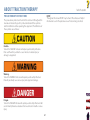
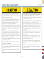
New Innovation For A Classic Therapy! ® User Manual Model 4779 Tru-Trac® Traction Unit ISO 13485 CERTIFIED TABLE OF CONTENTS FOREWORD . . . . . . . . . . . . . . . . . . . . . . . . . . . . . . . . . . . . . . . . . 1 Product Description . . . . . . . . . . . . . . . . . . . . . . . . . . . . . . . . . . . . . . . . . . . . . . . . . . . 1 ABOUT TRACTION THERAPY. . . . . . . . . . . . . . . . . . . . . . . . 28 Precautionary Instructions. . . . . . . . . . . . . . . . . . . . . . . . . . . . . . . . . . . . . . . . . . . . . 2 Cautions . . . . . . . . . . . . . . . . . . . . . . . . . . . . . . . . . . . . . . . . . . . . . . . . . . . . . . . . . . . . . . 3 Warnings . . . . . . . . . . . . . . . . . . . . . . . . . . . . . . . . . . . . . . . . . . . . . . . . . . . . . . . . . . . . . 4 Dangers . . . . . . . . . . . . . . . . . . . . . . . . . . . . . . . . . . . . . . . . . . . . . . . . . . . . . . . . . . . . . . 5 Overview of Traction Therapy . . . . . . . . . . . . . . . . . . . . . . . . . . . . . . . . . . . . . . . . . . 6 Common Terms . . . . . . . . . . . . . . . . . . . . . . . . . . . . . . . . . . . . . . . . . . . . . . . . . . . . . . . 6 Indications. . . . . . . . . . . . . . . . . . . . . . . . . . . . . . . . . . . . . . . . . . . . . . . . . . . . . . . . . . . . 7 Contraindications . . . . . . . . . . . . . . . . . . . . . . . . . . . . . . . . . . . . . . . . . . . . . . . . . . . . . 7 NOMENCLATURE . . . . . . . . . . . . . . . . . . . . . . . . . . . . . . . . . 813 Base Unit - Front View . . . . . . . . . . . . . . . . . . . . . . . . . . . . . . . . . . . . . . . . . . . . . . . 8-9 Base Unit - Rear View . . . . . . . . . . . . . . . . . . . . . . . . . . . . . . . . . . . . . . . . . . . . . 10-11 LCD Base. . . . . . . . . . . . . . . . . . . . . . . . . . . . . . . . . . . . . . . . . . . . . . . . . . . . . . . . . . . . .12 Symbol Definitions . . . . . . . . . . . . . . . . . . . . . . . . . . . . . . . . . . . . . . . . . . . . . . . . . . .13 SPECIFICATIONS. . . . . . . . . . . . . . . . . . . . . . . . . . . . . . . . . . . . 14 Unit Dimensions and Specifications . . . . . . . . . . . . . . . . . . . . . . . . . . . . . . . . . . .14 SETUP. . . . . . . . . . . . . . . . . . . . . . . . . . . . . . . . . . . . . . . . . . . 1519 Contents of Carton . . . . . . . . . . . . . . . . . . . . . . . . . . . . . . . . . . . . . . . . . . . . . . . . . . .15 Mounting Unit on Table . . . . . . . . . . . . . . . . . . . . . . . . . . . . . . . . . . . . . . . . . . . . . .16 Initial Unit Setup . . . . . . . . . . . . . . . . . . . . . . . . . . . . . . . . . . . . . . . . . . . . . . . . . 17-18 Attaching The Patient Switch Hook . . . . . . . . . . . . . . . . . . . . . . . . . . . . . . . . . . . .19 OPERATION . . . . . . . . . . . . . . . . . . . . . . . . . . . . . . . . . . . . . 2030 Patient Preparation. . . . . . . . . . . . . . . . . . . . . . . . . . . . . . . . . . . . . . . . . . . . . . . 20-21 Operating Controls - Home Screen . . . . . . . . . . . . . . . . . . . . . . . . . . . . . . . . 22-24 Adjusting Traction During Treatment . . . . . . . . . . . . . . . . . . . . . . . . . . . . . . . . . .25 Saving Treatment to a Patient Data Card. . . . . . . . . . . . . . . . . . . . . . . . . . . 26-28 Retrieving Data from Existing Patient Data Card . . . . . . . . . . . . . . . . . . . . . . .28 Tru-Trac® Traction Unit Erasing Patient Data Card. . . . . . . . . . . . . . . . . . . . . . . . . . . . . . . . . . . . . . . . . . . . .29 User Protocols . . . . . . . . . . . . . . . . . . . . . . . . . . . . . . . . . . . . . . . . . . . . . . . . . . . . . . .30 ACCESSORIES . . . . . . . . . . . . . . . . . . . . . . . . . . . . . . . . . . . 3132 TROUBLESHOOTING . . . . . . . . . . . . . . . . . . . . . . . . . . . . . 3336 Troubleshooting . . . . . . . . . . . . . . . . . . . . . . . . . . . . . . . . . . . . . . . . . . . . . . . . . 33-34 Error Messages. . . . . . . . . . . . . . . . . . . . . . . . . . . . . . . . . . . . . . . . . . . . . . . . . . . 35-36 MAINTENANCE . . . . . . . . . . . . . . . . . . . . . . . . . . . . . . . . . . . . . 37 Cleaning . . . . . . . . . . . . . . . . . . . . . . . . . . . . . . . . . . . . . . . . . . . . . . . . . . . . . . . . . . . . .37 Calibration Requirements. . . . . . . . . . . . . . . . . . . . . . . . . . . . . . . . . . . . . . . . . . . . .37 Service . . . . . . . . . . . . . . . . . . . . . . . . . . . . . . . . . . . . . . . . . . . . . . . . . . . . . . . . . . . . . .37 WARRANTY . . . . . . . . . . . . . . . . . . . . . . . . . . . . . . . . . . . . . . . . 38 FOREWORD Tru-Trac® Traction Unit This manual has been written for the operators of the Tru-Trac traction unit. It contains general instructions for operation, precautionary instructions, and maintenance recommendations. In order to obtain maximum life and efficiency from your Tru-Trac traction unit, and to assist in the proper operation of the unit, read and understand this manual thoroughly. The specifications put forth in this manual were in effect at the time of publication. However, owing to Chattanooga Group's policy of continuous improvement, changes to these specifications may be made at any time without obligation on the part of Chattanooga Group. Before administering any treatment to a patient, you should become acquainted with the operating procedures, as well as the indications, contraindications, cautions, warnings, and dangers. Consult other resources for additional information regarding the application of traction therapy. Product Description The Tru-Trac traction unit is a simple to use digital touch screen user interface traction unit that offers static, intermittent, and cyclic traction with user definable hold, rest, and treatment times. Patient Pain Profiles are recorded before and after treatment with a Numeric Pain Scale, VAS (Visual Analog Scale), and Pain Map for each patient. Once treatment parameters are customized for a patient, clinicians can store them as either the default user protocol or as one of ten user defined protocols. The Tru-Trac traction unit contains a Patient Data Card port, providing access to store the above session parameters on Patient Data Cards. ©2005 Encore Medical Corporation or its affiliates, Austin, Texas, USA. Any use of editorial, pictorial, or layout composition of this publication without express written consent from the Chattanooga Group of Encore Medical, L.P. is strictly prohibited. This publication was written, illustrated, and prepared for print by the Chattanooga Group of Encore Medical, L.P. 1 ABOUT TRACTION THERAPY Tru-Trac® Traction Unit NOTE: Throughout this manual “NOTE” may be found. These Notes are helpful information to aid in the particular area or function being described. PRECAUTIONARY INSTRUCTIONS The precautionary instructions found in this section and throughout this manual are indicated by specific symbols. Understand these symbols and their definitions before operating this equipment. The definitions of these symbols are as follows: CautionText with a “CAUTION” indicator will explain possible safety infractions that could have the potential to cause minor to moderate injury or damage to equipment. WarningText with a “WARNING” indicator will explain possible safety infractions that will potentially cause serious injury and equipment damage. DangerText with a “DANGER” indicator will explain possible safety infractions that are imminently hazardous situations that would result in death or serious injury. 2 ABOUT TRACTION THERAPY Tru-Trac® Traction Unit • Do not remove the cover. This may cause unit damage, malfunction, • Read, understand, and practice the precautionary and operating • • • • • • • instructions. Know the limitations and hazards associated with using any electrical traction device. Observe the precautionary and operational decals placed on the unit. Use this unit only with tables, stands, power cord, and accessories specifically designed and manufactured by Chattanooga Group. Not adhering to this guideline may cause damage to the unit, malfunction, electrical shock, fire, or personal injury. This unit should be operated, transported, and stored in temperatures between 16° C and 38° C (60° F and 104° F) or atmospheric pressure range between 700-1060 hPa, with relative humidity ranging from 30% - 60%. Do not operate the unit when connected to any unit other than Chattanooga Group devices. Do not use devices manufactured by other companies on Chattanooga Group equipment. Chattanooga Group is not responsible for any consequence resulting from using products manufactured by other companies. The unit should be routinely checked before each use to determine all controls function normally. Handle the unit with care. Inappropriate handling of the unit may adversely affect its characteristics. Before each use, inspect the Traction Cord for wear. Prolonged wear on the cord will cause it to break, which may cause sudden release of traction pressure on a patient. Test the Patient Interrupt Switch cable before each use for proper operation. • • • • • • 3 electrical shock, fire, or personal injury. There are no user-serviceable parts inside the unit. If a malfunction occurs, discontinue use immediately, disconnect the Mains Power Cord from the outlet, and consult the dealer for repair service. Do not use sharp objects such as a pencil point or ballpoint pen to operate the buttons on the LCD base as damage may result. Do not permit any foreign materials or liquids to enter the unit. Take care to prevent any foreign materials including, but not limited to, inflammables, water, and metallic objects from entering the unit. These may cause unit damage, malfunction, electrical shock, fire, or personal injury. Do not disassemble, modify, or remodel the unit or accessories. This may cause unit damage, malfunction, electrical shock, fire, or personal injury. Do not use the traction unit near devices such as X-ray units or diathermy units. These units may emit high frequency noise that may affect the operation of the unit. If you have difficulty operating the unit after carefully reviewing this operator’s guide, contact your Chattanooga Group dealer for assistance. Failure to use and maintain the traction unit and its accessories in accordance with the instructions outlined in this manual will invalidate your warranty. ABOUT TRACTION THERAPY Tru-Trac® Traction Unit • This device should only be used under the continued supervision of a • • • • • • • • The traction unit should only be used by a qualified licensed licensed practitioner. Use of controls or adjustments or performance of procedures other than those specified herein may result in a hazardous traction related injury. Before connecting the unit to an electrical outlet, make certain the unit is electronically grounded by connecting only to a grounded electrical service receptacle conforming to the applicable national and local electrical codes. Do not use a damaged Mains Power Cord. Using a damaged Mains Power Cord may cause unit damage, malfunction, electrical shock, fire, or personal injury. If the Mains Power Cord becomes damaged, discontinue use immediately and contact the dealer for replacement of the Mains Power Cord. This device should be kept out of the reach of children. Always hand tighten the Lock Knob securely to avoid any slippage. Care must be taken when operating this equipment around other equipment. Potential electromagnetic or other interference could occur to this or to the other equipment. Try to minimize this interference by not using other equipment in conjunction with it. The Patient Interrupt Switch must be in the patient’s grasp throughout the traction therapy. • • • 4 practitioner in a position of supervision during traction therapy. For that reason, do not attempt to put yourself in traction with this unit. In the event of a loss of power to the unit, traction tension should only be released by gradually lengthening the patient harness adjustment straps. Dispose of all products in accordance with local and national regulations and codes. In the event that an Error message or Warning appears beginning with a 2 or 3, immediately stop all use of the system and contact the dealer or Chattanooga Group for service. Errors and Warnings in these categories indicate an internal problem with the unit that must be tested by Chattanooga Group or a Field Service Technician certified by Chattanooga Group before any further operation or use of the unit. Use of a unit that indicates an Error or Warning in these categories may pose a risk of injury to the patient, user or extensive internal damage to the unit. ABOUT TRACTION THERAPY Tru-Trac® Traction Unit • Do not connect the unit to an electrical supply without first verifying that the power supply is the correct voltage. Incorrect voltage may cause unit damage, malfunction, electrical shock, fire, or personal injury. Your unit was constructed to operate only on the electrical voltage specified on the Voltage Rating and Serial Number plate. Contact your Chattanooga Group dealer if the unit is not properly rated. 5 ABOUT TRACTION THERAPY Tru-Trac® Traction Unit Static Traction Therapy This term denotes that a steady amount of traction is applied for periods from a few minutes up to 99 minutes. The shorter duration is usually coupled with more weight. Static lumbar traction is most effective if a split table is utilized to reduce friction. It is important that it is the type that maintains constant tension. This way, any slack developed as the patient relaxes during the traction therapy is automatically taken up and the desired amount of traction is maintained. Static traction is sometimes referred to as sustained traction. OVERVIEW OF TRACTION THERAPY Effects of Traction Therapy The Tru-Trac traction device provides a treatment in static, intermittent, and cyclic distraction forces to relieve pressures on structures that may be causing pain of skeletal or muscular origin (cervical, thoracic, lumbar, hip, wrist, shoulder). Therapeutic distraction can be applied in a variety of programmable patterns, cycles and functions. COMMON TERMS Progressive Traction Progressive traction refers to a traction phase during the treatment when the tension gradually increases. Intermittent Traction Therapy This form of traction alternates traction tension between tension levels - Maximum and Minimum - every few seconds throughout the timed treatment. It is also most effective if a split table is used to reduce friction when giving lumbar traction. In the progressive and regressive phases, the traction unit pulls to the calculated tension, holds for the set hold time, then drops to 50% of this tension, holds the set rest time and then repeats this step for the number of steps selected. However, once the minimum level is reached, the traction unit uses the minimum level for the rest time. Regressive Traction Regressive traction refers to a traction phase during the treatment when the tension gradually decreases. TX (Traction) TX (Traction ) refers to the type of traction used during a treatment. There are three modes to choose from: Static, Intermittent or Cyclic Traction Mode. Steps The term “step” refers to the increment in which the traction tension is either increased or decreased during therapy. Cyclic Traction Cyclic traction refers to progressive (gradually increasing traction tension) and regressive (gradually decreasing traction tension) phases of the traction program being repeated continuously throughout the entire course of the traction treatment. 6 ABOUT TRACTION THERAPY Tru-Trac® Traction Unit INDICATIONS CONTRAINDICATIONS The Tru-Trac traction device provides traction and mobilization of skeletal structures and skeletal muscles. Traction is contraindicated for the following: • Structural disease secondary to tumor or infection The Tru-Trac traction device may be used to relieve peripheral radiation/ sciatica and pain associated with: • Protruding discs • Bulging discs • Herniated discs • Degenerative disc disease • Posterior facet syndrome • Acute facet problems • Radicular pain • Prolapsed discs • Patients with vascular compromise • Any condition for which movement is contraindicated • Spinal root impingement • Hypomobility • Degenerative joint disease • Facet syndrome • Compressions fracture • Joint pain • Discogenic pain • Patients with acute strains, sprains, and inflammation which would be aggravated by traction therapy • Patients with joint instability of the spine • Pregnancy • Osteoporosis • Hiatus hernia • Claustrophobia The Tru-Trac traction device achieves these effects through decompression of intervertebral discs, that is, unloading due to distraction and positioning. 7 NOMENCLATURE Tru-Trac® Traction Unit BASE UNIT FRONT VIEW The Base Unit serves to house the mechanical and electrical components that provide the actual traction tension for the Tru-Trac traction unit under the electronic control and supervision of the Controller. Touch Screen User Interface Traction Cord To prevent wear and fraying, the unit should be mounted facing toward the desired direction of pull so that the Traction Cord does not contact the side of the slot from which it extends. Traction Cord Clevis Attachment Slots Should rope fray or damage to the rope or knot be apparent from visual inspection, immediately stop use of the unit and contact the Dealer or Chattanooga Group for service. Do not attempt to repair the rope. Patient Interrupt Switch Receptacle An improperly tied knot may result in injury. Do not attempt to retie the knot unless properly trained. 8 NOMENCLATURE Tru-Trac® Traction Unit BASE UNIT FRONT VIEW Accessory Clip The Accessory Clip allows you to attach the desired accessory (i.e., Spreader Bar or traction harnesses) to the unit. Patient Interrupt Switch Receptacle The Patient Interrupt Switch Receptacle is located on the front of the unit. Clevis Attachment Slots The Clevis Attachment Slots serve as a connection point for other traction apparatus (not included), such as cervical or wrist. The Patient Interrupt Switch is essential for the functioning of the unit. If it is not connected, or if it is malfunctioning, the unit will not work. Do not use the Clevis as a handle to pick up or carry the unit. 9 NOMENCLATURE Tru-Trac® Traction Unit BASE UNIT REAR VIEW Screen Contrast Control Lock Knob The rear view of the base unit is the site of electric current control and surge protection, and serves as a connection point for both the traction controls and safety features of the Tru-Trac traction unit. Power On/Off Switch The Power On/Off Switch is a toggle switch located on the back of the unit. This switch controls the flow of electricity from the outlet to the unit. Power On/Off Switch Mains Power Cord Receptacle Mains Power Cord Receptacle The Mains Power Cord Receptacle accepts the Mains Power Cord (female end). Screen Contrast Control The Screen Contrast Control is used to set a comfortable viewing of brightness of the touch screen user interface. 10 NOMENCLATURE Tru-Trac® Traction Unit BASE UNIT REAR VIEW Lock Knob The Lock Knob is used to clamp the Tru-Trac traction unit to the base (i.e. pedestal, traction stand). 11 NOMENCLATURE Tru-Trac® Traction Unit LCD BASE (1) LED Indicator (Power On/Off) This indicator will illuminate when the unit is powered on. NOTE: The LED indicator will blink when the unit goes in screen saver mode (the screen will go blank after twenty minutes of inactivity). Simply touch the screen to reactivate. (2) Clinical Resources This button allows you to change the following features of the traction unit: Patient Card User Protocols Name Retrieve Protocol Edit Treatment Being Setup Save Protocol Erase Patient Card Reset Default Protocol Utilities Unit Settings (3) Stop This button will stop the treatment program. Traction tension goes to zero. (4) Pause This button will pause the treatment program. Traction tension goes to zero. Press the pause button again to resume treatment program and traction tension. (5) Start Touch this button to start the treatment program. (6) Patient Data Card Port Access port to insert a Patient Data Card to save and retrieve patient treatments. The LCD Base serves as a programming terminal during the selection of the traction parameters, as well as a display showing all the factors affecting the traction during therapy. Traction parameters are selected with the buttons on the LCD Base and the touch screen user interface. The LCD and beeper make various audio and visual indications, and warn the operator when unsuitable parameters are chosen. 1 4 2 3 5 6 12 NOMENCLATURE Tru-Trac® Traction Unit SYMBOL DEFINITIONS Below are the definitions for all of the Symbols used on the Tru-Trac traction unit hardware and software. Study and learn these symbols before any operation of the unit. System Hardware Symbols System Software Symbols Contrast Control Stop Treatment Patient Interrupt Switch Move UP On/Off Switch Pause Treatment Patient Card Move DOWN Data Port Start Treatment Clinical Resources Accept and Return Push Lock Knob Cancel Lock/ Unlock Lock Knob Back Home 13 SPECIFICATIONS Tru-Trac® Traction Unit UNIT DIMENSIONS AND SPECIFICATIONS Width . . . . . . . . . . . . . . . . . . . . . . . . . . . . . . . . . . . . . . . . . . . . . . . . . . .24 cm (9.5 in) Depth . . . . . . . . . . . . . . . . . . . . . . . . . . . . . . . . . . . . . . . . . . . . . . . . . 45 cm (17.5 in) Height . . . . . . . . . . . . . . . . . . . . . . . . . . . . . . . . . . . . . . . . . . . . . . . . .45 cm (17.5 in) Meets Directive 93 /42 /EEC IEC/UL/EN: 60601-1 60601-1-2 CAN C22.2 No. 601.1-M90w/AZ Weight Standard Weight . . . . . . . . . . . . . . . . . . . . . . . . . . . . . . . . . . .14 kg (30 lbs/134 N) Shipping Weight . . . . . . . . . . . . . . . . . . . . . . . . . . . . . . . . . . .18 kg (40 lbs/178 N) Power Voltage . . . . . . . . . . . . . . . . . . . . . . . . . . . . . . . . . . . . . . . . . . .100V-240V (50/60Hz) Power Consumption . . . . . . . . . . . . . . . . . . . . . . . . . . . . . . . . . . . . . . . . . . . . .75 VA Current Consumption . . . . . . . . . . . . . . . . . . . . . . . . . . . . . . . . . . . .3.2 Amps Max Electrical Class . . . . . . . . . . . . . . . . . . . . . . . . . . . . . . . . . . . . . . . . . . . . . . . . . . Class I Electrical Type . . . . . . . . . . . . . . . . . . . . . . . . . . . . . . . . . . . . . . . . . . . . . . .Type B Height Traction Modes Static, Intermittent, Cyclic, and their combinations. Traction Type: Mechanical LCD Display: High contrast monochrome touch screen Traction Tension Parameters Traction Period Hold Period Rest Period Traction Tension Progressive and Regressive Steps Minimum 1 minute 0 seconds 0 seconds 0 kg (0 lb/0 N) Maximum Increments 99 minutes 1 minute 99 seconds 1 second 99 seconds 1 second 90 kg (200 lb/890 N) 1 kg (1 lb/5 N) 1 step 9 steps 1 step 14 De pth h dt Wi SETUP Tru-Trac® Traction Unit CONTENTS OF CARTON Remove the Tru-Trac traction unit and all accessories from the shipping cartons. Visually inspect for damage. Report any damage to the carrier immediately. Contents of Cartons: • Tru-Trac Traction Unit • Patient Data Cards (5) • Patient Interrupt Switch • Patient Interrupt Switch Hook Kit • Mains Power Cord • User Manual NOTE: When shipping the unit back to the dealer or factory, make certain the original packaging is used. If the original packaging is not available, contact Chattanooga Group to obtain the following packaging materials for shipment: 48093 48094 48092 48095 Left Inner Pack Right Inner Pack Shipping Box Shipping Bag Any damage sustained from improper packaging may render the warranty null and void. 15 SETUP Tru-Trac® Traction Unit MOUNTING UNIT ON TABLE 1. To secure the Tru-Trac traction unit to the mounting surface, push the Lock Knob down and turn left to loosen the clamp. Fit the unit to the mounting surface and turn right to tighten the clamp down onto the mounting surface. Push the Lock Knob again to secure the unit to the mounting surface. 2. Remove the cover on the back of the unit and connect the Mains Power Cord (female end) to the Mains Power Cord Receptacle. 3. Verify that there is a good connection between the Mains Power Cord and the Mains Power Cord Receptacle. Always make certain that the Mains Power Cord is properly plugged into the unit. 4. Check the voltage rating on the serial plate located on the back of the unit. Plug the Mains Power Cord into a 100V-240V AC outlet, as required. Replace the cover on the back of the unit. The Tru-Trac traction unit was designed to be utilized with Chattanooga Group traction tables: Do not operate the unit when connected to any unit other than Chattanooga Group devices. Do not use devices manufactured by other companies on Chattanooga Group equipment. Chattanooga Group is not responsible for any consequence resulting from using products manufactured by other companies. To prevent accidental disengagement, this unit must be securely attached to the mounting surface of the pedestal or traction stand. It is the responsibility of the user to verify the adequacy of the installation before use in patient therapy. NOTE: The Tru-Trac traction unit should be mounted facing the direction of pull so the Traction Cord does not contact the side of the slot from which it extends. 16 SETUP Tru-Trac® Traction Unit INITIAL UNIT SETUP Accessing User Utilities Clinic Name Press the Clinic Name Button. Enter the Clinic Name on the keyboard. To save the Clinic Name as entered, press the Return Arrow Button. To discard the Clinic Name, press the Cancel (X) Button. NOTE: The default of the Clinic Name is set as Chattanooga Group. Turn the unit On. Press the Clinical Resources button. Press the Unit Settings button under the Utilities section. Unit Volume Press the Volume Button until the desired unit volume is achieved. There are six settings: Off, X-Low, Low, Med, High and X-High. Each time the Volume Button is pressed, the setting displayed will also give three audible tones of that level. NOTE: The default of the unit volume is set at Medium. Unit of Measure There are three units of measure to choose from: kilograms (kg), pounds (lbs), and newtons (N). Press the Unit of Measure Button to toggle to the desired unit of measure and the setting will automatically save. NOTE: The default of the unit of measure is set in kilograms (kg). Set Date and Time Press the Set Date and Time Button. Press the Move Up or Down Arrow Button for the respective area (Year, Month, Day, Hour and Minute) until the desired change is displayed. NOTE: The time is set in a 24-hour format. 17 SETUP Tru-Trac® Traction Unit INITIAL UNIT SETUP Reset Unit Settings Press the Reset Unit Settings Button to restore the unit defaults (Clinic Name, Volume, Unit of Measure, and Language). This control will not change the Date and Time nor will it affect any of the User Protocols stored in the unit. Reset Default Protocols Press the Reset Default Protocols to restore all protocols to factory settings. NOTE: All User Protocols will be removed. To return to the unit Home Screen, press the Home button. Select Language To change the language displayed on the unit, press the Language Button until the desired language is displayed and the setting will automatically save. The available languages are: • English (Default) • French • Spanish • Portuguese • Norwegian • Finnish • Greek • German • Italian • Dutch • Danish • Swedish • Turkish NOTE: The default of Language is set as English. 18 SETUP Tru-Trac® Traction Unit ATTACHING THE PATIENT SWITCH HOOK Insert the Patient Switch Hook Cover to cover the hook screw hole. The Patient Switch Hook may be placed on either the left or right side of the unit to hook the Patient Interrupt Switch. A screw hole cap with the Chattanooga Group logo is located on both sides of the traction unit. Using a screwdriver, pop the screw hole cap off. The Patient Interrupt Switch can now be placed on the Patient Switch Hook. Place the Patient Switch Hook over the screw hole and tighten the Hook Screw in place. 19 OPERATION Tru-Trac® Traction Unit PATIENT PREPARATION 3. Verify that there is a good connection between the Patient Interrupt Switch and the Patient Interrupt Switch Receptacle. Traction therapy may be given by or on order of a qualified licensed practitioner. For best results, the person administering the treatment must be familiar with the principles of traction therapy and be able to choose the correct mode of traction, traction forces, and treatment times. Any settings or types of traction mentioned in this manual are for illustrative and expository purposes only. Each patient should be individually assessed to determine the appropriateness of the parameter settings prior to use. NOTE: The Patient Interrupt Switch must be plugged in for the unit to operate. 4. Test the Patient Interrupt Switch by pressing the red button. A warning message will be displayed saying The Patient Interrupt Switch has been pressed. Touch the screen to continue. Always test the Patient Interrupt Switch cable before each use for proper operation. A licensed practitioner experienced with traction therapy must be familiar with all instructions contained in this manual before traction therapy. Do not attempt to become familiar with the Tru-Trac traction unit while administering traction therapy on a patient. 5. Give the Patient Interrupt Switch to the patient, instructing that pressing the red button will stop the treatment. To prepare the patient for traction therapy, do the following: 1. Turn the unit on from the Power On/Off Switch, located on the back of the unit. Wait about five seconds for the unit to go through initialization before attempting any further patient preparation procedures. 2. Attach the Patient Interrupt Switch by inserting the male end of the cable into the Patient Interrupt Switch Receptacle located on the front of the unit. The Patient Interrupt Switch must be in the patient’s grasp throughout the traction therapy. 20 OPERATION Tru-Trac® Traction Unit PATIENT PREPARATION 6. Position the patient on the appropriate type of table in accordance with the instructions supplied with the table. 7. Fit the appropriate traction harness on the patient by following the fitting instructions supplied with the type of harness to be used. 8. Tighten any slack in the harness that may have occurred during positioning so that it fits the patient according to the manufacturer’s instructions. NOTE: It is usually easier to align the harness on patients while they are standing, and then tighten the harness after positioning them on the table. 9. Push and hold the Rope Release Button on the touch screen and slowly pull the end of the Traction Cord out from the traction unit. 10. Attach the Accessory Clip to the connection point of the traction harness, according to the manufacturer’s instructions. In the event of a loss of power to the unit or when quick release is needed, traction tension should only be released by loosening the patient harness adjustment straps. 21 OPERATION Tru-Trac® Traction Unit OPERATING CONTROLS HOME SCREEN The touch screen user interface allows the operator to access and setup for therapy in the following areas of the Home Screen: NOTE: Should you make a mistake while entering data, you may correct by re-pressing the appropriate key and re-entering the data. 12 1 11 NOTE: On the user interface touch screen, any parameters surrounded in white boxes are active and can be changed at any time. Any parameters surrounded in gray boxes are inactive and cannot be changed. 10 2 3 (1) Traction Meter Displays the amount of tension being delivered to a patient (in kilograms, pounds, or newtons). 4 9 (2) Time Remaining Displays the approximate number of minutes that remain in the current traction therapy session. 8 13 5 (3) Time Remaining During Hold/Rest Cycles Displays an amount of time when a Hold or Rest cycle is occurring during treatment as well as show the number of minutes that remain in that cycle. 16 14 6 15 7 (4) Treatment Status Displays one of the following to show the current status of the treatment being performed: Setup, Running, Paused, and Completed. 22 OPERATION Tru-Trac® Traction Unit displays the approximate amount of time (in minutes) selected for the regressive phase of the traction program. OPERATING CONTROLS HOME SCREEN (5) Progressive There are two buttons to use under the Progressive section. The first button allows you to choose from Static or Intermittent Traction Mode to use during the Progressive phase of the traction therapy session. The second button allows you to enter the step number (1-9) desired in the Progressive phase of the traction therapy session. NOTE: The third box in the Progressive section is an inactive button that displays the approximate amount of time (in minutes) selected for the progressive phase of the traction program. (8) Rope Release Releases the Traction Cord in order to pull out of the unit freely for setup. To release the cord, either pull on the Traction Cord and it will release and feed out, or hold the Rope Release button down and pull the Traction Cord out. NOTE: If there is more than 2kg (5 lbs or 19N) of tension, the Rope Release button is disabled. (9) Rest Time Displays the amount of rest time (0-99 seconds) entered during setup. To enter the rest time, press the Rest Time button, then enter the desired rest time, using the number keypad. Press the Return Arrow button to accept. NOTE: The Rest Time can be changed during the traction therapy session by pressing the Rest Time button, then use the Up or Down Arrow buttons to make any changes. Press the Return Arrow button to accept. (6) TX (Traction) There are two buttons to use under the TX section. The first button allows you to choose from Static, Intermittent or Cyclic Traction Mode to use during the traction phase of the traction therapy session. The second button allows you to enter the amount of time in minutes (1-99) desired for the traction phase of the traction therapy session. NOTE: The TX Time can be changed during treatment. Press the TX Time Button and use the Up or Down Arrows to change the time in one minute increments. Press the Return Arrow to accept changes. (10) Hold Time Displays the amount of hold time (0-99 seconds) entered during setup. To enter the hold time, press the Hold Time button, then enter the desired Hold Time, using the number keypad. Press the Return Arrow button to accept. NOTE: The Hold Time can be changed during the traction therapy session by pressing the Hold Time button, then use the Up or Down Arrow buttons to make any changes. Press the Return Arrow button to accept. (7) Regressive There are two buttons to use under the Regressive section. The first button allows you to choose from Static or Intermittent Traction Mode to use during the Regressive phase of the traction therapy session. The second button allows you to enter the step number (1-9) desired in the Regressive phase of the traction therapy session. NOTE: The third box in the Regressive section is an inactive button that 23 OPERATION Tru-Trac® Traction Unit OPERATING CONTROLS HOME SCREEN (11) Minimum Level Displays the minimum traction tension entered during setup. To enter the minimum traction tension, press the Min Level button, then enter the desired minimum setting, using the number keypad. Press the Return Arrow button to accept. NOTE: The Minimum Traction Tension can be changed during the traction therapy session by pressing the Min Level button, then use the Up or Down Arrow buttons to make changes in 1 kg (1 lb or 1 N) increments. Press the Return Arrow button to accept. (13) Clinical Resources This button offers the following features of the traction unit: (See Patient Data Card and User Protocols in the Operation Section for more information) • Patient Card • Patient Card (Patient Name) • Edit Treatment Being Setup • Erase Patient Card • Protocols • Retrieve Protocol • Save Protocol • Utilities • Unit Settings (see Pages 17-18 for more information) (12) Maximum Level Displays the maximum traction tension entered during setup. To enter the maximum traction tension, press the Max Level button, then enter the desired maximum setting, using the number keypad. Press the Return Arrow button to accept. If the Maximum Level of traction tension is greater than 17 kg (39 lbs or 166 N), a message will be displayed saying "Cervical traction should not be performed with a tension greater than 17 kg (39 lbs or 166 N); indicate the type of traction to be performed". The Lumbar Button must be pressed to start treatment, otherwise press the Cervical button and re-enter the Maximum Level of traction tension to be lower than 18 kg (40 lbs or 176 N). NOTE: The Maximum Traction Tension can be changed during the traction therapy session by pressing the Max Level button, then use the Up or Down Arrow buttons to make changes in 1 kg (1 lb or 1 N) increments. Press the Return Arrow button to accept. (14) Stop Stops the treatment program. Traction tension goes to zero. (15) Pause Pauses the treatment program. Traction tension goes to zero. Press the Pause Button again to resume treatment program and traction tension. (16) Start Starts the treatment program. 24 OPERATION Tru-Trac® Traction Unit Traction therapy can be stopped at any time by pressing the Stop Button or by pressing the red button of the Patient Interrupt Switch. When the Stop Button is pressed: • the traction tension will decrease gradually. • the Traction Cord will release. • the audible tone sounds. • the Home Screen will return to Setup Mode. If necessary, check the patient’s harness and position on the table, and change the traction parameters. Restart traction therapy by pressing the Start Button. When the red button of the Patient Interrupt Switch is pressed: • the audible tone sounds. • the motor is stopped. • a warning will display saying The Patient Switch has been pressed. The treatment has been terminated. Touch the screen to acknowledge the warning and the tension will decrease to zero. • the Traction Cord will release. If the unit loses power: • the motor stops. When the traction therapy is finished, the audible tone sounds, the traction tension will decrease gradually, the Traction Cord will release, and a message will display saying treatment has been completed. Touch the screen to acknowledge the message. NOTE: The beeper will beep every 30 seconds until the screen is touched to acknowledge the message. ADJUSTING TRACTION DURING TREATMENT NOTE: Read and follow steps of the Patient Preparation section on Pages 20-21 as well as learn Operating Controls of the Home Screen to setup traction treatment. When the Start Button is pressed: • the audible tone sounds. • the Traction Cord tightens. • the traction therapy begins. • the LCD displays the maximum traction tension, the minimum traction tension, the hold time, the rest time, the current tension, the time remaining in the traction therapy, and the running status. • the LCD graph of the traction therapy becomes shaded as it goes through the treatment. NOTE: Monitor the traction therapy closely. When the Pause Button is pressed: • the audible tone sounds. • the traction therapy is paused. • the Traction Cord will release. • the tension goes to zero. NOTE: The Pause Button may be used to adjust the patient's harness or position during treatment. NOTE: Wait until all tension has released automatically before attempting to remove the harness from the patient. Release the patient from the traction harness according to the manufacturer’s instructions. Resume the traction therapy by pressing the Pause Button again. 25 OPERATION Tru-Trac® Traction Unit SAVING TREATMENT TO A PATIENT DATA CARD Pain Scale - There are eleven pain scale settings to choose from a numeric scale of 0 to 10. Press the arrows left to right from what the patient describes pain from being No Pain (0) to Worst Pain Possible (10). NOTE: If the patient is unsure of rating pain from a numeric scale, a visual pain scale is available. Toggle the middle button between the left and right arrows to choose between a Numeric or a Visual Analog Scale. Press the arrows left to right to move the visual bar from what the patient describes pain from being No Pain to Worst Pain Possible. The Tru-Trac traction unit incorporates a Patient Data Card interface that allows transfer of patient therapy data from the unit to the Patient Data Card. The unit allows storage and recall of the following patient session data onto the Patient Data Card: all therapy session parameters, before and after Patient Pain Profiles, and Session Notes. Each Patient Data Card can store multiple sessions and each session can be recalled within the unit. New Patient Data Card Setup Insert a new Patient Data Card (with the gold chip facing up) into the Patient Data Card port located on the front of the traction unit. NOTE: Insert the Patient Data Card before treatment. Press the Clinical Resources Button on the front of the traction unit. Press the Edit Current Pain Profile Button located in the Patient Card section of the menu. Pain Type - There are eleven pain types to choose from based on how the patient describes pain: Numbing, Dull Ache, Throbbing, Pulsing, Tingling, Nagging, Pinching, Burning, Shooting, Stabbing, Radiating, or None Selected. Enter the following information under the Pain Before Treatment column: 26 OPERATION Tru-Trac® Traction Unit SAVING TREATMENT TO A NEW PATIENT DATA CARD Pain Map - Press the Edit Pain Map button. Press the area of the body to highlight where the patient describes pain. Each time an area of the body diagram is pressed, a highlighted square is produced. Press the area again to remove the highlighted square. Once a therapy session has been completed, press the Clinical Resources Button. Press Edit/Save Completed Pain Profile Button to enter all post-treatment pain information after the therapy session. (See previous instructions for Pain Scale, Pain Type, and Pain Map and enter information under the Pain After column) to show any progress made from the treatment. NOTE: The Clear Button clears all highlighted areas of the body diagram. Press the Back Button or Home Button to begin Setup and to perform the patient therapy session. NOTE: Once pain information is entered, review all information to make sure of accuracy. Once saved, pain information cannot be changed. NOTE: All pain information can be edited during a patient therapy session by pressing the Clinical Resources Button and Edit Current Pain Profile Button. However, it is recommended to enter all pretreatment pain information before the patient therapy session. Press the Save to Patient Card button to save patient therapy session. This will save all session parameters, and pain information. 27 OPERATION Tru-Trac® Traction Unit After the Save to Patient Card button is pressed, a keyboard will be displayed to enter the patient's name, if the card is blank. Once the patient's name is entered, press the Return Arrow to accept. Press the Clinical Resources button on the front of the traction unit. Press the Patient Card (Patient's Name) Button located in the Patient Card section of the menu. NOTE: If the Patient Data Card is not inserted, this button is deactivated. A message will be displayed saying treatment has been saved to the Patient Card for (patient's name). Touch the screen to acknowledge. This will return you to the Home Screen. The treatment list is located on the right side. Press the Up or Down Arrows to select the desired treatment. Press the Return Arrow to accept. This will show the following information: Before and After Treatment Pain Information (Pain Map, Pain Scale and Pain Type) and Session Notes. Remove the Patient Data Card for filing with patient records. NOTE: Ten or more treatments can be saved on a Patient Data Card. Use one card per patient. The Patient Data Card can also be used with the optional Patient Data Management System. NOTE: The box located on the left side of the treatment list is a review of treatment parameters of the selected treatment. The review of the treatment shows the following information: Patient's Name, Date, Start Treatment Time, End Treatment Time, and Treatment Parameters. RETRIEVING DATA FROM EXISTING PATIENT DATA CARD Existing Patient Data Card Use Insert the Patient Data Card (with the gold chip facing up) into Patient Data Card port located on the front of the traction unit. Press Run This Treatment Button. Press the Start Button to begin treatment. 28 OPERATION Tru-Trac® Traction Unit ERASING PATIENT DATA CARD Insert the Patient Data Card (with the gold chip facing up), to be erased, into the Patient Data Card port located on the front of the traction unit. Press the Clinical Resources Button on the front of the traction unit. Press the Erase Patient Card Button located in the Patient Card section of the menu. When the Patient Data Card is erased, a message will be displayed. Touch the screen to acknowledge the message and it will return to the Clinical Resources Screen. 29 OPERATION Tru-Trac® Traction Unit USER PROTOCOLS Accessing User Protocols This library is a series of protocols created by the user and stored in the unit memory. The following information gives general instructions as to setup, saving and access of User Protocols. Should the Restore Default Protocol Button be pressed, through the Utilities section of the Clinical Resources Screen, all User Protocols will be permanently removed from the unit. NOTE: Ten User Protocols can be saved as well as a Default Protocol. Press the Clinical Resources Button on the front of the traction unit. Press the Retrieve Protocol Button located in the Protocols section of the menu. Set Up and Saving User Protocols The list of the User Protocols is located on the right side and the Default Protocol is located on the left side. Press the Page Up or Page Down Buttons to review the User Protocols. Select and edit the parameters of the desired treatment from the Home Screen. Press the Clinical Resources Button on the front of the traction unit. Select the desired User Protocol by pressing the number of the User Protocol button. Press the Save Protocol Button located in the Protocols section of the menu. Select the number of User Protocol to save the desired treatment to or select the Default Protocol Button to save treatment as the default. A message will be displayed saying Current Settings saved as Protocol #. Touch the screen to continue. 30 ACCESSORIES Tru-Trac® Traction Unit The following provides the users of the Tru-Trac traction unit the necessary information to order the replacement accessories most commonly used with the system. This list of replacement accessories are designed for use with Chattanooga Group traction devices. When ordering, provide the respective part number, description and quantity desired. Ref. Ref. Description Description 7040 Saunders Cervical Traction Device 1404 Cervical Traction Halter, Large 1450 Carpal-Trac 1405 Cervical Traction Halter, Adjustable 12540 Carpal-Trac Replacement Wrist Strap 1431 Universal Thoracic Restraint 48039 Traction Clevis 1421 Universal Single Pull Pelvic Belt 48082 Patient Interrupt Switch 1412 Double Pull Pelvic Belt, Medium 48018 Patient Switch Hook Kit 1413 Double Pull Pelvic Belt, Large 48031 Replacement Traction Cord 1414 Double Pull Pelvic Belt, X-Large 27465 Patient Data Cards (25/pack) 1433 Heavy Duty Pelvic Traction 2768 Patient Data Management System 1432 Two Straps (Thoracic Restraint) TXA-1 Accessory Package 1434 Heavy Duty Pelvic Belt Includes: 1 Adjustable Cervical Traction Halter, 1 Heavy Duty Pelvic Traction Set, 2 TX Pillows and Covers, and 1 43 cm (17") Spreader Bar. 1435 Heavy Duty Thoracic Belt 60044 31 cm (12 in) Stainless Steel Spreader Bar 11261 Replacement Strap with Buckle 60030 43 cm (17 in) Stainless Steel Spreader Bar 1301 TX Cervical Pillow without Cover 1401 Universal Traction Halter 1341 TX White Cotton Pillow Cover 1403 Cervical Traction Halter, Medium 1440 31 ACCESSORIES Ref. Description 21284 Euro Mains Power Cord 78121 US Mains Power Cord 20971 Australian Mains Power Cord 20972 Swiss Mains Power Cord 20973 UK Mains Power Cord 20974 Danish Mains Power Cord 20975 Japanese Mains Power Cord 20976 Indian Mains Power Cord 20977 Israeli Mains Power Cord Tru-Trac® Traction Unit NOTE: The Mains Power Cord shipped with the System will accommodate the electrical requirements for the country of use. 32 TROUBLESHOOTING Tru-Trac® Traction Unit The Tru-Trac traction unit is designed with patient safety in mind. An error can be caused by both external and internal disturbances. Errors can be caused by disruptions in the power supply (such as a voltage break), and excess or inadequate voltage. Errors may also be caused by patient movement during the traction therapy. All traction unit errors and warnings are categorized by three numerical digits: Messages beginning with a 1 are general errors, a 2 symbolizes internal warnings and errors and a 3 signifies a critical error where the problem has locked up the unit. (See Warning on Page 36 for more information) Before calling for service, carefully review this operator’s guide. In the event you are still unable to correct the problem, contact your Chattanooga Group dealer for all repair service. Be certain to specify your model number, serial number, and a detailed description of the issue you encountered. Problem Possible Remedy The Power On/Off Switch is in the “ON” position nothing happens. • Verify the Mains Power Cord is properly connected to the power supply outlet. • Return to Chattanooga Group for replacement. The LED Indicator (Power On/Off) Light glows, but there is nothing displayed on the LCD, or the LCD displays confusing wording. • Verify the voltage from the power supply of the electrical outlet is the same as that is listed on your Voltage Rating and Serial Number Plate. • The LCD contrast may need to be adjusted. Adjustment knob on the back of LCD Display. The LED Indicator (Power On/Off) blinks nothing is displayed on the screen. • The unit is in Screen Saver Mode. Touch the screen or any button to reactivate the unit. The Patient Interrupt Switch is not working. • Make sure the Patient Interrupt Switch is properly connected to the Patient Interrupt Switch Receptacle. The Rope Release will not work. • Release all tension on the rope. • Shake the rope while holding down the Rope Release Button. • Turn unit off and return to Chattanooga Group for repair. 33 TROUBLESHOOTING Tru-Trac® Traction Unit Problem Possible Remedy Unable to properly read Patient Data Card. • Properly insert a Patient Data Card. • Attempt to use a known good Patient Data Card. • If problem persists, contact Chattanooga Group for service. Attempted to use an Invalid Patient Data Card. • Properly insert a Patient Data Card. • Attempt to use a known good Patient Data Card. • If problem persists, contact Chattanooga Group for service. No Session Data is available on the inserted Patient Data Card. • Save session data to Patient Data Card. • Attempt to use a known good Patient Data Card. • If problem persists, contact Chattanooga Group for service. Patient Data Card is full. • Purchase additional Patient Data Cards from an authorized Chattanooga Group dealer. • Save to the Patient Data Management System (PDMS). 34 TROUBLESHOOTING Tru-Trac® Traction Unit ERROR MESSAGES CODE NO. PROBLEM PROBABLE CAUSE 100 NO TENSION AT START OF TX Treatment has been running for eight seconds, but no tension is detected on the rope. 101 PATIENT SWITCH PRESSED The patient has pressed the patient switch. 102 PATIENT SWITCH NOT PLUGGED IN The Patient Interrupt Switch is unplugged. 104 NO TRACTION TREATMENTS ON CARD The Patient Card Button has been selected on the Utilities Screen, but no traction treatments were found on the card. 105 NO PATIENT CARD IN UNIT The Save to Card Button has been selected, but no Card is inserted into the unit. 106 NOT PATIENT CARD The Save to Card Button has been selected, but the card currently inserted is not a Patient Data Card. 107 PATIENT CARD IS FULL The Save to Card Button has been selected, but the Patient Data Card currently inserted is full. 108 PATIENT NAME CANNOT BE BLANK User has typed in a blank patient name. 111 CONTROL SW UPGRADE SIZE ZERO Error upgrading control board software. 112 MOTOR SW UPGRADE SIZE ZERO Error upgrading motor board software. 113 MAX TENSION IS ZERO User pressed Start, but has not yet set the Max. level value to a value greater than zero. 35 TROUBLESHOOTING Tru-Trac® Traction Unit ERROR MESSAGES In the event that an Error message or Warning appears beginning with a 2 or 3, immediately stop all use of the system and contact the dealer or Chattanooga Group for service. Errors and Warnings in these categories indicate an internal problem with the unit that must be tested by Chattanooga Group or a Field Service Technician certified by Chattanooga Group before any further operation or use of the unit. Use of a unit that indicates an Error or Warning in these categories may pose a risk of injury to the patient, user or extensive internal damage to the unit. 36 MAINTENANCE Tru-Trac® Traction Unit CLEANING SERVICE NOTE: Before cleaning, disconnect the unit from the power source. Should the Tru-Trac Traction Unit require service, contact the selling dealer or Chattanooga Group Service Department. All returned units to the factory for service must include the following: Periodically, clean the system with a clean, lint free cloth moistened with water and mild antibacterial soap. If a more sterile cleaning is needed, use a cloth moistened with an antimicrobial cleaner. WARRANTY REPAIR/OUT OF WARRANTY REPAIR 1. Written statement containing the following information; Do not submerse the system in water. Should the unit accidentally become submersed, contact the dealer or Chattanooga Group Service Department immediately. Do not allow cleaning solutions or water to enter the ventilation holes in the unit. This could permanently damage the unit. Do not attempt to use a unit that has been wet inside until inspected and tested by a Service Technicians certified by Chattanooga Group. • RA Number - Obtain from Factory • Unit Model Number • Unit Serial Number • Contact person with Phone and Fax Numbers • Billing Address (for Out of Warranty Repair) • Shipping Address (Where to Ship Unit after Repair) • Detailed Description of Problem or Symptoms 2. Copy of original invoice issued at purchase of the unit. 3. Ship unit to Factory in the original container with all accessories and information as required in item one (1) above to: Touch Screen Cleaning Clean unit display lens using a soft damp cloth, moistened with warm water and soap if necessary. Chattanooga Group 4717 Adams Road Hixson, TN 37343 USA Phone: +1-423-870-7200 Fax: +1-423-870-2046 Do Not Use alcohol or chlorine based solvents as this may damage the display. When shipping the unit to the dealer or factory, make certain the original packaging is used. If the original packaging is not available, contact Chattanooga Group to obtain the packaging materials listed on Page 15 for shipment. Any damage sustained from improper packaging may render the warranty null and void. CALIBRATION REQUIREMENTS Annual factory calibration is required for Tru-Trac traction units. The unit should be sent to the factory or a Service Technician certified by Chattanooga Group for this procedure. Service to these units should be performed only by a Service Technician certified by Chattanooga Group. 37 WARRANTY Tru-Trac® Traction Unit Chattanooga Group (“Company”) warrants that the Tru-Trac Traction Unit (“Product”) is free of defects in material and workmanship. This warranty shall remain in effect for two years (24 months) from the date of original consumer purchase. If this Product fails to function during the two year warranty period due to a defect in material or workmanship, Company or the selling dealer will repair or replace this Product without charge within a period of thirty (30) days from the date on which the Product is returned to the Company or the dealer. All repairs to the Product must be performed by a service center authorized by the Company. Any modifications or repairs performed by unauthorized centers or groups will void this warranty. The warranty period for the accessories shipped with the unit is 180 days. Accessories consist of the materials shipped with the unit. To participate in warranty coverage, this Product’s warranty registration card (included with Product) must be filled out and returned to the Company by the original owner within ten (10) business days of purchase. This Warranty Does Not Cover: Replacement parts or labor furnished by anyone other than the Company, the selling dealer or an certified Company service agent. Defects or damage caused by labor furnished by someone other than Company, the selling dealer or an certified Company service agent. Any malfunction or failure in the Product caused by product misuse, including, but not limited to, the failure to provide reasonable and necessary maintenance or any use that is inconsistent with the Product User’s Manual. COMPANY SHALL NOT BE LIABLE IN ANY EVENT FOR INCIDENTAL OR CONSEQUENTIAL DAMAGES. Some locations do not allow the exclusion or limitation of incidental or consequential damages, so the above limitation or exclusion may not apply to you. To obtain service from Company or the selling dealer under this warranty: 1. A written claim must be made within the warranty period to the Company or the selling dealer. Written claims made to the Company should be sent to: 4717 Adams Road P.O. Box 489 Hixson, TN 37343 USA Phone: +1-423-870-7200 Fax: +1-423-870-2046 2. The Product must be returned to the Company or the selling dealer by the owner. This warranty gives you specific legal rights and you may also have other rights which vary from location to location. The Company does not authorize any person or representative to create for it any other obligation or liability in connection with the sale of the Product. Any representation or agreement not contained in the warranty shall be void and of no effect. THE FOREGOING WARRANTY IS IN LIEU OF ALL OTHER WARRANTIES, EXPRESSED OR IMPLIED, INCLUDING ANY WARRANTY OR MERCHANTABILITY OR FITNESS FOR A PARTICULAR PURPOSE. 38 New Innovation For A Classic Therapy! ISO 13485 CERTIFIED 4717 Adams Road P.O. Box 489 Hixson, TN 37343 U.S.A. +1-423-870-7200 USA +1-423-870-2046 USA FAX www.chattgroup.com 0413 48034A ©2005 Encore Medical, L.P.