1
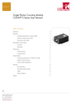
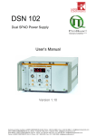
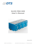
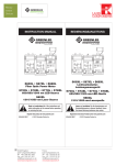
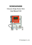
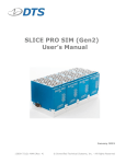
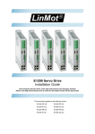
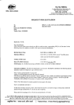
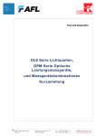
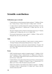
Detectors
Single Photon Counting Module
COUNT®-Series User Manual
Table of Contents
Introduction2
Operation2
Handling single photon counting modules
2
Electrical connections (rear side)
3
Powering up the module
3
Optimizing performance
3
Mounting the Count-Module
4
Front-side4
Base plate
4
Performance5
Spectral response
5
Timing resolution
5
Correction factor
6
Technical Data
7
Technical Specifications for COUNT® module
7
Technical Specifications for COUNT BLUE module
8
Technical Specifications for COUNT® NIR module
9
Absolute Maximum Ratings
10
Interface information
10
Product number designations
10
®
Support11
1
Germany & Other Countries
Laser Components GmbH
Tel: +49 8142 2864 – 0
Fax: +49 8142 2864 – 11
[email protected]
www.lasercomponents.com
Detectors
Single Photon Counting Module
COUNT®-Series - User Manual
Introduction
Laser Components’ COUNT® series of single photon counting modules has been developed to offer a unique combination of high photon detection efficiency, wide dynamic range and ease of use for photon counting applications.
Combining Laser Components’ ultra-low—noise VLoK silicon avalanche photodiode with specially developed quenching and signal processing electronics, the module offers everything needed for single photon detection from 400
– 1000 nm. Incoming photons generate corresponding electrical pulses which may be conveniently read out at the
TTL output. The optional FC connector provides a convenient method for connecting the module to the sample using a
multimode optical fiber.
Operation
Handling single photon counting modules
The avalanche photon diode inside the COUNT® is an extremely sensitive device. It can be permanently damaged
by over-exposure to intense light.
The COUNT® contains a high voltage supply. Users may be injured if the case is opened. All internal settings are
pre-set; there are no user adjustments necessary. Opening the case will invalidate the warranty.
Excessive light level (e.g. daylight) might damage a powered COUNT®. Precautions should be taken to avoid such
situations or, alternatively, to monitor the count rate and eventually shut down the power to the COUNT® using e. g.
the DSN102 from PicoQuant GmbH.
When the COUNT® detector is mounted on another instrument, ensure that the optical connection is light-tight.
Handle the COUNT® detector with care. Do not drop it or expose it to excessive mechanical shocks or vibrations.
Heat Dissipation
In order to avoid damage to the module adequate heat sinking must be provided by placing or mounting the
module onto a suitable heat sink, e.g. an optical table.
Gating function, TTL output and power supply
Always switch off the module before connecting or disconnecting the gating input and the TTL output.
In order to not damage the APD it is recommended to put ferrite beads or ferrite clamp-ons on all cables
leading to the APD. This includes TTL output, gating input and power supply input.
2
Germany & Other Countries
Laser Components GmbH
Tel: +49 8142 2864 – 0
Fax: +49 8142 2864 – 11
[email protected]
www.lasercomponents.com
Detectors
Single Photon Counting Module
COUNT®-Series - User Manual
Electrical connections (rear side)
1
2
+12V
GND
3
1 - Power Supply (2-pin LEMO connector, type EXG.0B.302). This is for the optional +12V DC power adapter
COUNT®-PSU (sold separately). Alternatively, the appropriate cable from the dual-SPAD power supply DSN
102 (PicoQuant) or from the COUNT®-PSU is connected here. The appropriate mating connector is the LEMO
FGG.0B.302.CLAD42.
2 - Gating input (SMA female). Connect a TTL signal to this input in order to enable (TTL high, >2.4V) or disable (TTL
low) counting.
3 - TTL signal output (LEMO connector, type EPS-00.250). Use a double shielded RG223/U coaxial cable to connect his signal to e. g. the dual-SPAD power supply DSN 102 (PicoQuant). Suited Lemo connector types are e. g.
FFS.00.250 or the Lemo/BNC adapter type ABF.00.250.CTA (supplied).
Note: the output should be terminated into a 50 Ohms load.
Powering up the module
Before powering up the module it is strongly advised to make sure that no light reaches the sensor.
In order to power up the module, simply plug-in the AC adapter in the power supply connector or, in case you are
using the DSN 102 dual-SPAD power supply, turn on the DSN and power up the corresponding SPAD channel. After
power on, allow 30 seconds settling time in which the sensor will be cooled down to its operating temperature.
NOTE: the COUNT® will not generate any output signal until the operating temperature has been reached.
Optimizing performance
The COUNT® shows best performance if the light is focussed to a small spot (<50 µm diameter) in the center of the
sensor area. Please also see Fig. 3 of the COUNT® datasheet. Mounting the COUNT® on a suitable x, y, z-translation table or other means of positioning mechanics is therefore recommended. Off-center focussing or overfilling
the sensor area might lead to an effective lower detection efficiency and/or increased FWHM of the photon timing
resolution.
The FC-connector version is pre-aligned for fibers of core diameter <105 µm and requires no further optimisation.
3
Germany & Other Countries
Laser Components GmbH
Tel: +49 8142 2864 – 0
Fax: +49 8142 2864 – 11
[email protected]
www.lasercomponents.com
Detectors
Single Photon Counting Module
COUNT®-Series - User Manual
Mounting the Count-Module
The COUNT® can be either mounted from the front-side or by using the dedicated mounting holes on the base plate.
Front-side
1
2
The front side of the COUNT® provides two mounting options:
1 - a C-mount thread (1-32 UN), compatible with, for example, the LINOS tube system
2 - two mounting holes with 8-32 UNC thread, depth 8 mm.
Please note that you still have to support the weight of the detector when this mounting style is used!
Base plate
The base plate of the COUNT® provides 6 mounting holes (3 holes each side) with a diameter of 3.9 mm.
4
Germany & Other Countries
Laser Components GmbH
Tel: +49 8142 2864 – 0
Fax: +49 8142 2864 – 11
[email protected]
www.lasercomponents.com
Detectors
Single Photon Counting Module
COUNT®-Series - User Manual
Performance
Spectral response
The COUNT® can be used to detect single photons in the spectral range between approx. 400 nm and 1100 nm.
The typical detection efficiency as a function of wavelength is shown in figure 1.
Fig. 1: Typical detection efficiency as a function of wavelength
Timing resolution
The single photon timing resolution of the COUNT® depends on three factors and is generally different for every
single module (please see the test report of your COUNT® for details):
1. Detection wavelength - the best photon timing resolution (i. e. smallest FWHM) is generally achieved around 680
nm. The FWHM increases slightly towards blue and NIR detection wavelengths.
2. Focusing quality - for optimum timing resolution the light should be focused to a small spot (<50 µm) in the center
of the sensor. Off-center focusing or overfilling the sensor area might lead to an increased FWHM of the photon
timing resolution.
3. Counting rate - the FWHM of the photon timing resolution increases at high counting rates. Especially at counting
rates >1 million counts / second the FWHM may be double the value at low counting rates.
The temporal stability of the pulse output also depends on the counting rate. In general, high counting rates lead to a
relative shift of the pulse to later times. The total shift may reach 800 ps at counting rates >1 million counts / second.
5
Germany & Other Countries
Laser Components GmbH
Tel: +49 8142 2864 – 0
Fax: +49 8142 2864 – 11
[email protected]
www.lasercomponents.com
Detectors
Single Photon Counting Module
COUNT®-Series - User Manual
Correction factor
Every COUNT® has an inherent dead time of approx. 45 ns after detecting a photon. During this dead time, the
COUNT® is "blind" and can not detect further photons. As a consequence, the measured counting rate is lower than
the true actual counting rate. The true actual counting rate can be calculated from the measured counting rate as follows:
Ractual =
Rmeasured
1 − Rmeasured ⋅ T D
where Ractual = actual counting rate
Rmeasured = measured counting rate
TD = SPAD dead time
The dead time effect can also be seen as a deviation from the unity of the ratio between the actual counting rate and
the measured counting rate. Given a dead time and equation 1, it is possible to calculate a correction factor as a
function of the measured count rate as shown in figure 2.
Fig. 2: Correction factor calculated for a dead time of 80 ns
6
Germany & Other Countries
Laser Components GmbH
Tel: +49 8142 2864 – 0
Fax: +49 8142 2864 – 11
[email protected]
www.lasercomponents.com
Detectors
Single Photon Counting Module
COUNT®-Series - User Manual
Technical Data
Technical Specifications for COUNT® module
Parameter
Min.
Spectral range
400
Typ.
Dark count rate
COUNT®-10C
COUNT®-20C
COUNT®-50C
COUNT®-100C
COUNT®-250C
Photon detection efficiency Pd1 at:
405 nm
670 nm
810 nm
nm
10
20
50
100
250
Counts/s
Counts/s
Counts/s
Counts/s
Counts/s
Pd variation at constant temperature
TBC
%
Active area diameter (nominal)
100
µm
1000
ps
2
3
0.2
4
Dead time
42
1
%
45
ns
Gating input voltage
Gating on (= disable module)
Gating off (= enable module)
TTL low (<0.5)
TTL high (>2.4)
V
V
Gating input response time
Gating on (= disable module)
Gating off (= enable module)
15
60
20
65
ns
ns
TTL output pulse length
15
17
ns
TTL output pulse amplitude (into 50 Ohm)
Delay between photon impact and TTL
pulse
Supply voltage
Germany & Other Countries
Laser Components GmbH
Tel: +49 8142 2864 – 0
Fax: +49 8142 2864 – 11
[email protected]
www.lasercomponents.com
1000
%
%
%
Afterpulsing probability
7
Unit
15
70
50
Timing resolution
5
60
40
Max.
11.5
3
V
30
ns
12.0
12.5
V
Supply current (switch on)
0.8
A
Supply current (operation at 1 Mcps)
0.2
A
1
Specifications valid for modules without FC-connector.
2
The active area of the integrated Si-APD is larger than 100 µm.
The FC-version is optimised for optical fibers with core diameter <105 µm. The pre-aligned GRIN lens focuses
the light onto a spot of <70 µm diameter in the centre of the detector. The NA of the fiber used with the module is
recommended to be ≤ 0.29.
3
Timing resolution depends on count rate and wavelength.
4
Defined for a time interval from 0 to 500 ns.
Detectors
Single Photon Counting Module
COUNT®-Series - User Manual
Technical Specifications for COUNT® BLUE module
Parameter
Min.
Spectral range
350
Typ.
Dark count rate
COUNT®-10B
COUNT®-20B
COUNT®-50B
COUNT®-100B
COUNT®-250B
Photon detection efficiency Pd1 at:
405 nm
532 nm
670 nm
Unit
1000
nm
10
20
50
100
250
Counts/s
Counts/s
Counts/s
Counts/s
Counts/s
55
70
55
%
%
%
Pd variation at constant temperature
TBC
%
Active area diameter (nominal)
100
µm
1000
ps
0.2
%
45
ns
Gating input voltage
Gating on (=disable module)
Gating off (=enable module)
TTL low (<0.5)
TTL high (>2.4)
V
V
Gating input response time
Gating on (=disable module)
Gating off (=enable module)
15
60
20
65
ns
ns
TTL output pulse length
15
17
ns
Timing resolution
50
60
50
Max.
2
3
Afterpulsing probability
4
Dead time
42
TTL output pulse amplitude (into 50 Ohm)
Delay between photon impact and TTL
pulse
Supply voltage
11.5
3
V
30
ns
12.0
12.5
V
Supply current (switch on)
0.8
A
Supply current (operation at 1 Mcps)
0.2
A
Specifications valid for modules without FC connector.
The active area of the integrated Si-APD is larger than 100 µm.
The FC-version is optimised for optical fibers with core diameter <105 µm. The pre-aligned GRIN lens focuses
the light onto a spot of < 70 µm diameter in the centre of the detector. The NA of the fiber used with the module
is recommended to be ≤ 0.15. For fibers with a NA ≤ 0.29 and a core diamenter of ≤ 105 μm special
FC-versions are available for wavelengths ≥ 500 nm.
3
Timing resolution depends on count rate and wavelength.
4
Defined for a time interval from 0 to 500 ns.
1
2
8
Germany & Other Countries
Laser Components GmbH
Tel: +49 8142 2864 – 0
Fax: +49 8142 2864 – 11
[email protected]
www.lasercomponents.com
Detectors
Single Photon Counting Module
COUNT®-Series - User Manual
Technical Specifications for COUNT® NIR module
Parameter
Min.
Spectral range
400
Typ.
Dark count rate
COUNT-50N
COUNT-100N
COUNT-250N
COUNT-500N
Photon detection efficiency Pd1 at:
670 nm
810 nm
nm
50
100
250
500
Counts/s
Counts/s
Counts/s
Counts/s
Pd variation at constant temperature
TBC
%
Active area diameter (nominal)
100
µm
1000
ps
2
3
0.2
4
Dead time
42
1
%
45
ns
Gating input voltage
Gating on (= disable module)
Gating off (= enable module)
TTL low (<0.5)
TTL high (>2.4)
V
V
Gating input response time
Gating on (= disable module)
Gating off (= enable module)
15
60
20
65
ns
ns
TTL output pulse length
15
17
ns
TTL output pulse amplitude (into 50 Ohm)
Delay between photon impact and TTL pulse
Supply voltage
Germany & Other Countries
Laser Components GmbH
Tel: +49 8142 2864 – 0
Fax: +49 8142 2864 – 11
[email protected]
www.lasercomponents.com
1000
%
%
Afterpulsing probability
9
Unit
70
60
Timing resolution
60
50
Max.
11.5
3
V
30
ns
12.0
12.5
V
Supply current (switch on)
0.8
A
Supply current (operation at 1 Mcps)
0.2
A
1
Specifications valid for modules without FC-connector
2
The active area of the integrated Si-APD is larger than 100 µm.
The FC-version is optimised for optical fibers with core diameter <105 µm. The pre-aligned GRIN lens focuses the light onto a
spot of <70 µm diameter in the centre of the detector. Please also see Fig. 2 and 3.
3
Timing resolution depends on count rate and wavelength.
4
Defined for a time interval from 0 to 500 ns
Detectors
Single Photon Counting Module
COUNT®-Series - User Manual
Absolute Maximum Ratings
Supply voltage
Operating temperature
Min.
Typ.
Max.
Unit
11.5
12.0
12.5
V
40
°C
85
%
70
°C
20
MCounts/s
10
Humidity at 40°C
Storage temperature
-20
Count rate
Interface information
▪▪
▪▪
▪▪
▪▪
▪▪
Power Supply: LEMO connector, item number FGG.0B.302.CLAD42
(optional COUNT power supply is available upon request product code COUNT-PSU).
Gate input: SMA connector
TTL output: LEMO connector, compatible with LEMO/BNC adapter ABF.00.250.CTA.
Optical input (FC connector version): compatible with standard FC/PC-connector, suitable for fiber core diameters
up to 105 µm.
Product number designations
C O U N T®
XX Y
Dark count rate
B = COUNT® BLUE
20 = 20 c/s
C = COUNT®
Standard
100 = 100 c/s
250 = 250 c/s
500 = 500 c/s
Germany & Other Countries
Laser Components GmbH
Tel: +49 8142 2864 – 0
Fax: +49 8142 2864 – 11
[email protected]
www.lasercomponents.com
FC-Connector (optional)
10 = 10 c/s
50 = 50 c/s
10
FC
N = COUNT® NIR
Detectors
Single Photon Counting Module
COUNT®-Series - User Manual
Support
Your COUNT® module has undergone thorough testing at Laser Components. It is stable and reliable. Nevertheless,
we continually make improvements that will be incorporated into future versions.
In any case, we would like to offer you our complete support. Please do not hesitate to contact Laser Components
iif you would like assistance with your system. If you observe any errors, please e-mail a detailed description of the
problem and relevant circumstances, to [email protected]. Your feedback will help us to improve the product and documentation.
Of course we also appreciate good news. If you have obtained exciting results with one of our systems, please let us
know, and where appropriate, mention us in your publications.
Retraction of old devices
Waste electrical products must not be disposed of with household waste. This equipment should be taken to your local recycling center for safe treatment.
WEEE-Reg.-No. De96457402
Product Changes
LASER COMPONENTS reserves the right to make changes to the product(s) or information contained herein without
notice. No liability is assumed as a result to their use or application.
Ordering Information
Products can be ordered directly from LASER COMPONENTS or its representatives. For a complete listing of representatives, visit our website at www.lasercomponents.com
08/15 / V19 / HW / lcp/count-series-user-manual
Custom designed products are available on request.
11
Germany & Other Countries
Laser Components GmbH
Tel: +49 8142 2864 – 0
Fax: +49 8142 2864 – 11
[email protected]
www.lasercomponents.com