1
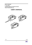
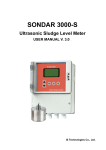
SONDAR4000
Ultrasonic Sludge Density Meter
User Manual V.3.8
IS Technologies Co., Ltd.
SONDAR 4000
Aug. 2003
COPYRIGHT
© IS Technologies Co., Ltd. All rights reserved. No part of this publication may be reproduced, transmitted,
transcribed, stored in a retrieval system, or translated into any language in any form without the written permission
of IS Technologies Co., Ltd.
WARRANTY AND LIABILITY
IS Technologies Co., Ltd. guarantees for a period of 1 year from the date of delivery that it will either exchange or
repair any part of this product returned to IS Technologies Co., Ltd. if it is found to be defective in material or
workmanship, subject to the defect not being due to unfair wear and tear, misuse, modification or alteration,
accident, misapplication or negligence.
DISCLAIMER
IS Technologies neither gives nor implies any process guarantee for this product, and shall have no liability in
respect of any loss, injury or damage whatsoever arising out of the application or use of any product or circuit
described herein.
Every effort has been made to ensure accuracy of this documentation, but IS Technologies cannot be held liable
for any errors.
TECHNICAL ENQUIRIES
Please contact IS Technologies Co., Ltd. for technical support.
IS Technologies Co., Ltd.
Bucheon Techno Park 203-504, 192, Yakdae-dong, Wonmi-gu, Buchon-si, Kyeonggi-do, Korea
Tel: 82-32-621 2606
Fax: 82-32-621 2612
Web Site: http://www.sondar.com
e-mail: [email protected]
2
SONDAR4000
Table of Contents
1. Product Information
…………………………………………………………………………………… 4
Introduction
Features
………………………………………………………………………………………… 4
……………………………………………………………………………………………… 4
Specifications
………………………………………………………………………………………… 5
Measurement Principles ……………………………………………………………………………… 6
Structure
……………………………………………………………………………………………… 6
2. Installation
……………………………………………………………………………………………
Dimension……………………………………………………………………………………………
Cable Connection
Installation
Controller
Button
7
…………………………………………………………………………………… 8
……………………………………………………………………………………………
Zero Setting & Span Setting
3. How To Use
7
9
………………………………………………………………………
10
……………………………………………………………………………………………
12
…………………………………………..…………………………………………………
12
……………………………………………………………………………………………………12
Operation Mode
Setting Mode
4. Programming
……………………………………………………………………………………… 13
…………………………………………………………………………………………
15
……………………………………………………………………………………………
16
Change of Set Values
………………………………………………………………………………
16
………………………………………………………………………………………………
22
6. Troubleshooting ……………………………………………………………………………………………
23
7. Option Records
24
5. Maintenance
……………………………………………………………………………………………
3
SONDAR4000
1. Product Information
Introduction
Sondar 4000 is an in-line sludge density meter measuring the density of sludge flowing in the pipe
in the manner of ultrasonic attenuation method.
Since the user can adjust the setting range of current output and relay, it allows active generation of
alarm and control inside the processor.
Sondar 4000 satisfies the waterproofing requirements of IP65, displays the density value at a
graphic LCD, and has 5 buttons for various setting.
Features
-
Insertion of sensor into pipe allows in-line density measurement and it can be applicable to
various kinds of sludge.
-
It measures the temperature of target medium for temperature compensation, resulting in more
accurate measurement.
-
Measured sludge density is displayed in digital mode (% or mg/L).
-
Current output (4 mA ~ 20 mA) in proportion to measured sludge density.
-
Able to set the sludge density corresponding to output of 4 mA and 20 mA.
-
Having two separate SPDT relays that the user can freely set.
-
Depending on setting conditions, abnormal current output (3.8 mA or 21 mA) can be resulted on
wrong operation, enabling remote detection of such wrong operation.
-
All functions can be operated only with 5 buttons.
-
The setting values are saved at EEPROM, so they are maintained even when the power is cut.
-
Free voltage
4
SONDAR4000
Specifications
Physical
Controller
191×240×133mm
Sensor
Depends on pipe size
Weight
Sensor Material
Around 3.5kg (controller)
S.S,316
Range
0~2, 5, 10, or 20% solids
Environmental
IP Rating (electronics housing)
IP65(Controller)
Max. & Min. temperature (electronics)
-20 ºC to +60 ºC(Controller), -30 to +80°C(Sensor)
7m (Standard)
RTX cable length
Performance
Accuracy
0.5% of full scale
Range(pipe diamenter)
80A~600A
Frequency
1 MHz
Displayed Information
Density, Temperature, Alarm, Statue Graphic LCD
Temperature Compensation
Fully compensated via integral temperature sensor over entire operational span
Outputs
Analogue output
4-20mA into Max 750Ω (user adjustable: 250Ω)
Fault condition alarm 3.8mA /Hold/21mA,
Setpoint Relay
2 SPDT Relays
Relay capacity
5A, AC250V
Communication Port
1 point RS-232C/RS-485(Option)
Programming
On-board programming
via 5 tactile push button buttons
Supply
Power supply
Applicable Channel
AC 90 ~ 260V, Less than 15VA(50Hz ~ 60Hz), DC24V(Option)
Sewage treatment plant: raw sludge line, excess sludge line, concentrated
sludge line
Wastewater treatment: return sludge line, digested sludge line
Chemical process, Pulp paper mill, Concentration process
5
SONDAR4000
Measurement Principles
In general, an ultrasonic density meter measures the density of a medium based on the attenuation
degree of received signals relative to transmitted signals.
As shown in the below figure, presence of particles in a medium results in scattering of ultrasonic
waves passing the medium, leading to reduction of received signals. Such attenuation of received
signals is used to determine the density of dissolved material, suspended solids, or organic solution.
At present, the ultrasonic density meter is used in the fields of wastewater treatment, livestock
waste treatment (sludge), pulp, and paper mill. Further, it has been increasingly used at various
food and chemistry processes.
It has the advantages of in-line density measurement without interference of flow as well as easy
maintenance. Since lots of bubbles can also disperse the ultrasonic signals and result in highdensity value, careful attention should be paid to occurrence of bubbles. In this case, a process of
removing bubbles in the manner of compression or with use of magnetism can be added to get
more accurate result.
Pipe
RX
RX
R
TX
TTX
< Principle of Ultrasonic Density Meter >
Structure
A sensor is inserted into the pipe and the sensor cable is connected to a controller through a
junction box. The controller controls the process according to the density-linked current output,
alarm, and error relay output.
Sondar 4000
Junction Box
MODE
Cable (Std. 7m)
SET
RUN
Ultrasonic Sludge Density Meter
4~20mA
5 SPDT Relay
RS232/485 (option)
TX/RX Sensor
Controller
6
SONDAR4000
2. Installation
Dimension
Controller
Sondar 4000
MODE
SET
RUN
Ultrasonic Sludge Density Meter
<Front & Base>
<Side>
<Back>
Sensor
S.S. Flange
To Controller
JUNCTION
BOX
140
32
60
50~220
48
12
144
<Immersion Type>
Cable Protector
<Pipe Type>
7
SONDAR4000
Cable Connection
Open a base cover and 23(27) terminals in one row are shown as follow:
1CH
2CH
SENSOR
RX+ RX- TX-
DIGITAL
TX+
TX
RX
GND
mA 1
+
-
R2
R1
NO
COM
NC NO
COM
ER
NC
NO
COM
NC
CLEAN
+
-
POWER
L
N
<Input & Output Terminals>
Terminal
Terminal
(1)
RX+
RX sensor's signal output wire connection
(2)
RX-
RX sensor's GND wire connection
(3)
TX-
TX sensor's GND wire connection
(4)
TX+
TX sensor's signal output wire connection
(5)
VCC
DC power
(6)
TX
When using RS232C, RS232C transmission connection/When
using RS485 interface, Y connection
Option
(7)
RX
When using RS232C, RS232C receipt connection/When using
RS485 interface, Z connection
Option
(8)
GND
GND for digital communication
(9)
mA+
Current output. 4~20mA outputs in proportion to density
(10)
mA-
Current output return
(11)
R1_NO
(12)
R1_ COM
(13)
R1_ NC
Alarm1 Relay's NC contact. When Relay does not operate, it
shorts with A1_COM.
(14)
R2_NO
Alarm2 Relay's NO contact. When Relay operates, it shorts with
A_2 COM.
(15)
R2_ COM
(16)
R2_ NC
Alarm2 Relay's NC contact. When Relay does not operate, it
shorts with A2_COM.
(17)
ER_NO
Fail Relay's NO contact. In the case of fail, it shorts with FA_COM.
(18)
ER_ COM
(19)
ER_ NC
Fail Relay's NC contact. When Relay does not operate, it shorts
with FA_COM.
(20)
CLAEN+
Solenoid Valve SSR(+) contact
(21)
CLEAN-
Solenoid Valve SSR(-) contact
L, N
Function
Remark
Max.750Ω
Alarm1 Relay's NO contact. On Relay operation, it shorts with
A1_COM.
Alarm1 Relay's COM contact.
Alarm2 Relay's COM contact.
Fail Relay's COM contact.
AC90~260V
AC power input
8
SONDAR4000
Installation
The following figures show the installation example.
Fixer
Sensor
detail A.
A.
JUNCTION
BOX
<Installation Diagram>
<Sensor Installation>
Installation Procedures
1. Pipe installation:
-
For stable flowing, installation should be conducted at a place distant from bent or expanded
portions (more than 5D).
-
Since accurate measurement is possible when the pipe is fully filled, installation should be
conducted to make the flow direction of bottom-up or to make the sensor connection axis
run parallel with the ground.
2. Sensor installation:
-
Remove any foreign or projected materials in the sensor fixation part in order to prevent any
damage in the course of sensor insertion.
-
Check if there is O-ring in the sensor fixation part.
-
Insert the sensor and completely fix it with use of a fixer.
3. Cable connection:
-
Use a specified cable to connect Junction Box with Controller.
-
Connect Controller's terminals
Important information
When installing the sensor, be sure to check if Junction Box and Controller have the same S/N
(shown on their labels). In the course of product release, zero setting and sensitivity adjustment were
conducted to reflect the installation conditions. Therefore, Controller and sensor with the same S/N
have to be connected. If normal temperature values are not displayed, check if RX and TX sensors
are correctly connected or TX sensor is damaged. TX sensor has the temperature sensor.
9
SONDAR4000
Zero Setting & Span Setting
Calibration Procedures
1. Press MODE button at operation mode
2. Go to option No. 18, by pressing Up/Down button
17. ZERO ADJ
*18. AUTO ZERO ADJ
19. SAPN ADJ
20. SPAN OFFSET ADJ
Important information
*
It is desirable to set 2- or 3-time value of average density as max. density.
*
Since presence of bubbles results in inaccurate measurement, be sure to remove all bubbles
if possible.
*
If there is a dramatic inflow of sludge into the pipe, accurate measurement can be done only
after the flow is stabilized.
Zero Setting
1. Fill the pipe with clear water and wait about 10 minutes until the flow becomes stabilized.
2. By pressing SET button, zero adjustment starts automatically.
AUTO ZERO
ADJUSTING……
SETTING :
150
C_COUNT :
3860
Auto SET? SET, NO? DOWN
VOLTAGE : 2.30V
DENSITY : 9.38%
-
When the output voltage is close to within 1%, Auto SET? SET, NO? DOWN message will
display.
Press SET button when the percentage is close to 0%.
Press DOWN button when the additional adjustment requires.
10
SONDAR4000
Span Setting
1. Introduce the sludge into the pipe and wait about 10 minutes until the flow becomes stabilized.
2. By pressing SET button, SPAN ADJ. option is shown as below figure.
3. Use Up/Down button to set the DEN: **.**% valve at desired level.
4. Press SET button to save the SPAN ADJ. value
17. ZERO ADJ -----[CAL]
17. ZERO ADJ -----[CAL]
18. AUTO ZERO ADJ
18. AUTO ZERO ADJ
*19. SPAN ADJ
*19. SPAN ADJ
SET1 :
150
DEN1 :
1.90%
20. SPAN OFFSET ADJ
11
SONDAR4000
3 How To Use
Controller
Open a base cover of Controller and 3 terminal blocks will be shown. A sensor signal wire is
connected to Rx/Tx sensor connection terminal. A control output and a current output are connected
to control terminal, while a power input is connected to power terminal.
Button
□
MODE Button
This button has a function of converting Operation Mode to Program Mode. Push of this
button at Operation Mode will show the options for Program Mode. Then, use UP or DOWN
button to go to other options.
△ UP / ∇ DOWN Button
This button is used to change the setting value of an option selected by Mode button. One
push results in increase by "1" unit, while continuous push results in continuous increase.
Change of more than 10 from the initial value makes change of ten figures. At more than ten
figures, 100 figures are changed. When Program Mode is not selected, it is used for movement
of option items.
□
SET Button
This button is used to change the setting values and save such changed values of option
selected. Also, it is used for movement of option items.
□
RUN Button
Push of this button results in return to Operation mode from Program Mode.
12
SONDAR4000
Operation Mode
There are two modes: Program Mode and Operation Mode. Program Mode is activated by Mode
button, while Operation Mode is activated by Run button.
At Program Mode, the values are set by Up or Down button. After completion of setting, push Set
button to save the setting values. Then, use Up or Down button to go to other option items or push
Run button to go back to Operation Mode.
1) LCD Display at Operation Mode
LCD shows the following display at Operation Mode.
5000
6.34%
TMP : +24 ℃
A1
A2
%
* 12.34 mA
10.00 %
< Display at Opeation Mode >
(1) □□.□□% - This indicates the density under measurement.
(2) TMP: □□℃ - This indicates the inside temperature. Since the temperature sensor is in the
inside of TX sensor, this means actual temperature of fluid under measurement.
(3) 00.00mA - This indicates current ouput of density
(4) Bar graph - This indicates a percentage of current density relative to maximum density. For
example, if the current density is 5% and max. density set by the user is 10%, the bar graph
shows 50% of full length.
(5) A1
A2
FAIL - A1 means that ALARM 1 RELAY is in operation, while A2 means that
ALARM 2 RELAY is also in operation. FAIL is shown when the device is in abnormal
operation. However, when FAIL is indicated, max. density is displayed.
(6) FS: □□.□□% - This indicates max. measurable density.
(7) TIME : - Month, Date, Year, Hour, Minute
13
SONDAR4000
2) Alarm Relay Operation
When the measured density reaches the specified Alarm density, the built-in Alarm Relay
operates to make output contact On or Off. The Alarm density can be set by the user.
Depending on the user's needs, RELAY 1 and 2 can be used for low-density alarm, high-density
alarm, control of sludge feed pump according to density, or control of sludge discharge pump.
Example 1: When Alarm 1 Relay is used for control of sludge feed pump
When 1.00% is set for Alarm 1 Relay On and 5.00% is for Alarm 1 Relay Off, the relay is On
when actual density becomes less than 1.00%. In this case, the sludge feed pump is also
turned on, leading to increase of density. Then, if the density reaches 5.0%, the relay is Off
to stop the pump.
Example 2: When Alarm 2 Relay is used for control of sludge discharge pump
When 8.0% is set for Alarm 2 Relay Off and 9.0% is for Alarm 2 Relay On, the relay is On
when actual density is more than 9.0%. In this case, the sludge discharge pump is also
turned on, leading to decrease of density. Then, if the density reaches 8.0%, the relay 2 is
Off to stop the pump.
3) Current Output and Alarm On Wrong Operation
When the device does not normally operate, a specific current output (selected by the user
among three options; 3.8 mA, Hold, or 21 mA) different from those under normal operation is
resulted, leading to operation of a relay for alarm of wrong operation. As a result, the fact of
wrong operation is informed to a remote operator.
4) Sensor Cleaning
Attachment of sludge to the sensor surface can affect actual measurement, so periodic cleaning
of the sensor surface is required. Sensor can be cleaned according to a specific period set by
the user.
Sensor is cleaned by operating the electronic SOL VALVE and spraying high-pressure water
over the sensor surface.
At a specified cleaning time set by the user, the density meter's SOL1 and SOL2 contacts
become ON, leading to operation of the electronic SOL VALVE.
14
SONDAR4000
Setting Mode
Password Check Mode
PASSWORD CHECK
PASSWORD CHECK
Password Number?
****
PASSWORD OK!
Password Number?
****
PASSWORD WRONG
RETURN MEASURE MODE
When the password is confirmed
When the password is wrong
Push of Mode button enters Password Check Mode. This is to prevent unauthorized change of
setting values. If wrong password is entered, a message of "PASSWORD ERROR!" and a message
of "RETURN OPER. MODE" are displayed at the same time. Then, the mode is returned to
Operation Mode. When the password is confirmed, a message of "PASSWORD OK!" is displayed
and you can go to next control mode.
15
SONDAR4000
4 Programming
Change of Set Values
Push Set button at the relevant option and the corresponding set value will be displayed. Push
Set button again and * will be indicated in front of the relevant option, which will be saved. Then,
use Up or Down button to move to other option.
Password Change
Factory Set= 0
*01. PASSWORD
02. UNIT SET
03. LOWCUT DENSITY
04. SPAN SCALE
-This option is to change password.
-Push Set button and use Up or Down button to set
the desirable password.
-After password setting, push Set button and use
Up/Down button to move to other option.
☞ (Mode → Set→ UP or DOWN→Set )
Display Unit
Factory Set= %
01. PASSWORD
*02. UNIT SET
03. LOWCUT DENSITY
04. SPAN SCALE
-This option is to choose the density display unit.
-Push Set button and use Up or Down button to
select % or mg/L.
-After setting, push Set button and use Up/Down
button to move to next option.
Low Cut
Factory Set= 0.50%
01. PASSWORD
02. UNIT SET
*03. LOWCUT DENSITY
- This option is to set min.density value display in
LCD. Lower than this values will be displayed as 0%
- Push Set button and use Up or Down button to set
the value.
04. SPAN SCALE
16
SONDAR4000
Span Scale
Factory Set= 10.00%
01. PASSWORD
02. UNIT SET
03. LOWCUT DENSITY
*04. SPAN SCALE
- This option is to set maximum density value.
- Push Set button and use Up or Down button to set
maximum density value.
- It is desirable to set 3- to 4-time value of average
density as max. density value.
4 mA Set Point
Factory Set= 0.00%
*05. 4mA SET POINT
06. 20mA SET POINT
07. OUPUT DAMPING
08. FAIL SAFE CURRENT
- This option is to set 4 mA output density value.
- Push Set button and use Up or Down button to
select 4mA output density.
- After setting, push Set button and use Up/Down
button to move to next option.
20 mA Set Point
Factory Set= 0.00%
05. 4mA SET POINT
*06. 20mA SET POINT
07. OUPUT DAMPING
- This option is to set 20 mA output density value.
- Push Set button and use Up or Down button to
select 20 mA output density.
- After setting, push Set button and use Up/Down
button to move to next option.
08. FAIL SAFE CURRENT
Output Damping
Factory Set= 10Sec
05. 4mA SET POINT
06. 20mA SET POINT
*07. OUPUT DAMPING
- This option determines the maximum rate at which
the unit will respond to an increase/decrease in
sludge density.
- Set longer time when the density is not stable
- Range : 1~1000sec
08. FAIL SAFE CURRENT
17
SONDAR4000
Fail Safe Current
Factory Set= 3.8mA
05. 4mA SET POINT
- This option is to set fail-safe time.
- Push Set button and use Up or Down button to set
06. 20mA SET POINT
value among 3.8/Hold/22mA
07. OUPUT DAMPING
*08. FAIL SAFE CURRENT
RELAY1 On Set
Factory Set= 1.0%
*09. RELAY1 ON
- This option is to set Relay 1 Relay On.
- Push Set button and use Up or Down button to set
10. RELAY1 OFF
11. RELAY2 ON
12. RELAY2 OFF
density value.
- It is desirable to set density value under
consideration of connection device and control
method.
RELAY1 Off Set
Factory Set= 1.5%
09. RELAY1 ON
- This option is to set Relay 1 Relay Off.
- Push Set button and use Up or Down button to set
*10. RELAY1 OFF
11. RELAY2 ON
12. RELAY2 OFF
density value.
- It is desirable to set density value under
consideration of connection device and control
method.
RELAY2 On Set
Factory Set= 9.0%
09. RELAY1 ON
- This option is to set Relay 2 Relay On.
- Push Set button and use Up or Down button to set
10. RELAY1 OFF
*11. RELAY2 ON
12. RELAY2 OFF
density value.
- It is desirable to set density value under
consideration of connection device and control
method.
18
SONDAR4000
RELAY2 Off Set
Factory Set= 8.5%
09. RELAY1 ON
- This option is to set Relay 2 Relay Off.
- Push Set button and use Up or Down button to set
10. RELAY1 OFF
11. RELAY2 ON
density value.
- It is desirable to set density value under
consideration of connection device and control
*12. RELAY2 OFF
method.
Select Detector
Factory Set= CH1
*13. SELECT DETECTOR
- This option is to set the measuring channel.
- This option is used only for dual channel model
14. DATA INTERVAL
15. DATA TREND
16. TRANSMIT POWER
.
Data interval
Factory Set= 1min
13. SELECT DETECTOR
*14. DATA INTERVAL
- This option is to set inverval of data saving.
(1, 5, 10, 30, 60, 120min)
- Presently saved data is removed once change this
value
15. DATA TREND
16. TRANSMIT POWER
- The value becomes the space when check the
density trend.
Data trend
100%
13. SELECT DETECTOR
14. DATA INTERVAL
50%
*15. DATA TREND
0%
16. TRANSMIT POWER
DEN:9.26% [92%]
19
1MIN
SONDAR4000
- To display the density trend.
- Display 100-point data and the interval of each point is set at precious option No. at 14
- The upper right figure shows the density trend in percentage relative to full scale
Transmit Power
Factory Set= 1min
13. SELECT DETECTOR
- This option is to set the strength of sensor power
- When small size of pipe in use, set the value small,
14. DATA INTERVAL
15. DATA TREND
*16. TRANSMIT POWER
and vice versa.
Note!!
Need to adjust zero and span set again, if this valve
is changed.
Zero Adjust
Factory Set= 100
*17. ZERO ADJ.
- This option is to adjust/change the zero value
manually.
18. AUTO ZERO ADJ.
19. SPAN ADJ.
20. SPAN OFFSET ADJ.
- This option is to adjust the amplification ratio of
intial signal reception
- The amplification ration goes up relative to set value
- Range : 1~255
Auto Zero Adjust
Factory Set= 100
.
17. ZERO ADJ.
- This option is to adjust the zero value automatically,
if this value is changed
*18. AUTO ZERO ADJ.
- Refer to Zero and Span setting at page 10.
19. SPAN ADJ.
20. SPAN OFFSET ADJ.
20
SONDAR4000
Span Adjust
Factory Set= 0
- This option is to adjust the span amplification ratio
17. ZERO ADJ.
- Refer to Zero and Span setting at page 10
18. AUTO ZERO ADJ.
- Range : 0~255
*19. SPAN ADJ.
20. SPAN OFFSET ADJ.
Span Offset Adjust
Factory Set= 0%
17. ZERO ADJ.
17. ZERO ADJ.
18. AUTO ZERO ADJ.
18. AUTO ZERO ADJ.
19. SPAN ADJ.
19. SPAN ADJ.
*20. SPAN OFFSET ADJ.
20. SPAN OFFSET ADJ.
X.XX% -------> 0.00%
[D1]
-
[D2]
This option is to compensate the density curve when the change of density is not linear against
ultrasonic attenuation. The present span density(X.XX%) will be shown on the left. The right
0.00% is flickering for desired span value setting.
[Ex. I]
5.00% ----->
2.00 %
[Ex. II]
10.00 %
10.00 %
.
7.00%
5.00%
5.00% ----->
7.00 %
5.00%
2.00%
0%
0%
21
SONDAR4000
5. Maintenance
Maintenance
1) Controller – Install it at a clean place without dust, particles, or other foreign materials, if
possible, and use the fine cloth to clean it.
2) Sensor – It is recommended to periodically check the cleanliness of the sensor surface. Clean
the sensor based on the user's experience. When the density of more than average value is
displayed, be sure to check the cleanliness.
3) Cable – Do not allow it to come into contact with solvent or chemicals. Place it at a place distant
from the motor, big machine, or others generating electric noise.
As shown in the below figures, when viscous materials are attached to the sensor (A), target
medium does not go up to the level of sensor (B), foreign materials are accumulated to block the
sensor surface due to low fluid speed (C), or there are lots of bubbles (D),
It is not possible to conduct normal measurement. Therefore, careful attention should be paid to
cleanliness of pipe and sensor. Further, appropriate actions should be taken to avoid bubbles for
more accurate measurement.
1/2" Ball V/V
Drain
(A)
(B)
(C)
22
(D)
SONDAR4000
6. Troubleshooting
If there are any wrong operations during installation or use of Sondar 4000 Ultrasonic Sludge Density
Meter, please refer to the following table.
Items
LCD
Display
Problems
1. Display is off.
2. Display flickers.
Remark
Solutions
* It is a problem of power supply to display board.
1) Check the power connection.
2) Check the flexible cable connection at the rear.
3) Check the flat cable connection between main board and
display board.
3. Display is not clear.
* It is a problem of LCD contrast adjustment.
1) Check the cable connection and separate the display
board to adjust the volume resistance.
Current
Output
1. The current output does not
match with the density value.
* The current output is displayed after conversion of digital
value
to
analog
one.
The
current
value
can
be
compensated at Engineering Mode.
1) Check mA Setpoint setting at Option 5 & 6.
2. Current output adjustment
3. The current output does not
work.
1) Compensate the current output at Engineering Mode 2.
* The lightening or wrong connection of polarity can
damage the current output element.
1) Check the connection status of current output terminal
block.
2) When the connection is correct, contact us.
Density
Display
Value
1. Display value is 0%.
* Since display value is a relative one, wrong adjustment of
ZERO ADJ in circuit may affect the display value.
1) Re-adjust Zero and Span setting.
2) When such condition is not corrected, contact us.
2. Display value is Full value.
* When foreign materials are attached to the sensor
surface, measurement is not possible. Or when there is no
RX signal due to wrong connection of sensor wires, only full
value is displayed.
1) Check if temperature value is normally displayed.
2) Check the connection of sensor. (cable)
- If there is no problem of sensor connection, such display
of only full value may be resulted from attachment of
foreign materials to the sensor surface.
3) Check the cleanliness of sensor.
3. Display value is not stabilized.
* When the sensor surface is not clean or the sensor
connection is not stable, RX signal is also unstable.
1) Check the cleanliness of sensor.
2) Adjust Damping rate.
Temp.
Display
Value
1. (-) value of temp. is displayed.
* Since temperature is used for density compensation,
temperature measurement should be normally continued.
1) Check the sensor connection at TX.
2. Temp. unstable change.
1) Contact us
23
SONDAR4000
7. Option Records
SONDAR 4000
No
Items
01
Setting
Range
Initial Values
PASSWORD CHANGE
0~1000
0
02
DISPLAY UNIT
%, mg/L
%
03
LOWCUT DENSITY
0.00% ~ Max. Density
0.1%
04
SPAN SCALE
0.00% ~ Max. Density
10%
05
4mA SET POINT
0.00%~ Max. Density
0%
06
20mA SET POINT
0.00%~Max. Density
10%
07
OUTPUT DAMPING
1 ~ 1000 sec.
100 sec.
08
FAIL CURRENT
3.8mA/Hold/21mA
3.8mA
09
RELAY1 ON
0.00% ~ Max. Density
1%
10
RELAY1 OFF
0.00% ~ Max. Density
1.5%
11
RELAY2 ON
0.00% ~ Max. Density
9.0%
12
RELAY2 OFF
0.00% ~ Max. Density
8.5%
13
SELECT DETECTOR
Present Time
14
DATE INTERVAL
15
DATA TREND
16
TRANSMIT POWER
17
ZERO ADJ
18
AUTO ZERO ADJ
19
SPAN ADJ
20
SPAN OFF ADJ
30sec.1minute,
5, 20,30 minutes
1 ~ 100
1 minutes
10
0 ~ 255
0 ~ 255
0.0V ~ 2.5V
0.0V
0.0% ~ Full Scale
0.0%
24
SONDAR4000