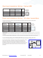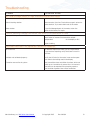
1
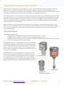
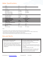
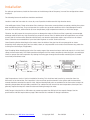
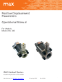
Positive Displacement
Flowmeters
Operational Manual
For Models
Model 241, 242
240 Helical Series
Positive Displacement Flow Meters
Max Machinery, Inc. 240 Series User Manual © Copyright 2015
Rev. 003Q4
1
Table of Contents
Before You Install....................................................................page 3
Meter General Description....................................................page 3
Transmitter General Description ....................................... page 4
Meter Specifications...............................................................page 5
Do and Don’ts...........................................................................page 5
Transmitter Specifications - Analog ................................. page 6
Transmitter Specifications - Frequency (Pulse)...............page 7
Installation................................................................................page 8
Piping Diagrams.......................................................................page 9
ANSI FlangeANSI Flange Stud Torque...............................page 9
Operation................................................................................ page 10
Troubleshooting......................................................................page 13
241 Helical Flow Meter.......................................................... page 14
242 Helical Flow Meter
Contact for Repairs & Calibration Services
Limited Warranty................................................................... page 15
Custom Instructions for Hazardous Locations/Explosion Proof Housing:
http://www.maxmachinery.com/content/explosion-proof-installation-instructions
DO NOT ATTEMPT TO INSTALL OR START FLOW METER WITHOUT READING THIS ENTIRE MANUAL
Max Machinery, Inc. (MMI) reserves the right to make changes to the product in this Instruction Manual to improve performance, reliability, or
manufacturability. Consequently, contact MMI for the latest available specifications and performance data. Although every effort has been made to
ensure accuracy of the information contained in this Instruction Manual, MMI assumes no responsibility for inadvertent errors.
Max Machinery, Inc. 240 Series User Manual © Copyright 2015
Rev. 003Q4
2
Before You Install
Thank you for choosing to install a Max Machinery precision flow meter. To ensure the best experience please take a
moment to read through this manual prior to installation.
When you purchased this meter a flow engineer helped determine many of the factors that will be reviewed on the
following pages. You may find it useful to fill out the form below and keep it in your files for reference.
When you are ready to do the installation there will be a few tools you will need:
Meter Installation:
The meter and transmitter
A signal cable (available from factory)
The display or signal processing device
Indicator Manual
Calibration Certificate
Bypass plumbing supplies
Many Max meters are installed and operate for decades, so having the following information in your records may prove
useful. We have provided this outline as a starting point.
Process Temperatures ____________________________ Fluid Viscosity_____________________________________
Operating Range _________________________________ Line Pressure_____________________________________
Max Sales # or PO #______________________________ Installation Date___________________________________
Meter Model # ___________________________________ Meter Serial #_____________________________________
Transmitter Model #______________________________ Transmitter Serial #________________________________
Notes: ______________________________________________________________________________________________
______________________________________________________________________________________________
______________________________________________________________________________________________
Meter General Description
The Max 240 Series Flow Meters are positive displacement helical rotor type units capable of precise measurements
over a wide range of flow rates and fluid viscosities.
The two sizes of this series (241 and 242) will measure flows from 0.1 L/min to 500 L/min. Material viscosities between 3
and 1,000,000 centipoise may be accommodated.
In a helical rotor type flow meter, a precise amount of the fluid being measured is trapped between the rotors as they
turn. This motion is used to turn a gear coupled to a magnet. An external transmitter senses the motion of the magnet
and converts this signal into a voltage, pulse or 4-20 mA current flow rate output. For some transmitter models, the
magnet is eliminated and the motion of the gear itself is sensed.
The Max Series 240 Meters are of simple and rugged construction. They can be expected to perform superbly if treated
within the confines of the design envelope. For this reason, it is important to read this manual and understand the
operational requirements and limits of the meter.
Our Technical Service staff will be happy to answer any questions that this manual does not cover.
Max Machinery, Inc. 240 Series User Manual © Copyright 2015
Rev. 003Q4
3
Transmitter General Description
Max transmitters are designed to work with the entire family of Max Flow Meters to provide extremely precise flow
measurement in a cost effective package. Different options of industrial housings or IP66 rated explosion proof
enclosures, combined with a choice of one-part and two-part, high temperature designs with remote electronics cover a
wide range of application environments – from the laboratory to harsh industrial processes.
This latest generation of transmitters use modern sensor technology coupled with advanced signal processing to deliver
high levels of performance and reliability. Hall sensors are used to detect the position of a driven magnet inside a Max
Flow Meter. Changes in position are tracked by a microprocessor, which generates an output proportional to the flow
rate. Advanced signal processing provides both fine angular resolution (0.36 degrees rotation) and rapid response
(output updated every one millisecond).
Max transmitters are typically mated to a mechanical flow meter, configured, and calibrated at the factory as a set.
This ensures accuracy and allows quick setup in the field. For field installations where the transmitter has not been set
up with a meter at the factory, an optional serial interface kit may be purchased to give full access to configuration
options and parameters.
Transmitter Features
High resolution measurement –
Analog Output: Configured output ranges to any value within ± 10 Vdc or ± 20 mA.
Frequency Output: Configured output resolution of 1 to 1000 pulses per revolution.
Linearization of up to 16 points to fully describe the flow meter’s output curve and achieve the highest system linearity over the meter’s entire operating range.
Compensation Algorithm – Compensates for variations in Hall sensor
and flow meter characteristics to provide a stable, undamped output
that accurately represents the instantaneous flow rate. This feature
is factory set when the meter and transmitter are mated together. If
the transmitter is changed, the compensation can be performed via a
button on the circuit board.
Anti-Dither Buffer - Masks the false output that may occur at very
low flow rates in the presence of vibration or hydraulic noise. If the
meter reverses direction the output signal will be interrupted for a
user selected portion of a meter rotation. Reverse flow exceeding
the buffer setting will result in an output proportional to reverse flow
rate. The buffer quantity can be set from 1% to 100% of a revolution.
Ex Proof Housing
Model 289
Model 295
Analog/ Frequency
Max Machinery, Inc. 240 Series User Manual © Copyright 2015
Rev. 003Q4
4
Meter Specifications
Model 1
Maximum flow rate,
Gal/min
Liters/min
Maximum pressure, bar (psi)
Standard NPT
600 lb ANSI RF flanges
1500 lb ANSI RF flanges
2500 lb ANSI RF flanges
Pressure drop, bar (PSI)
Operating maximum
Absolute maximum
100% flow, 3 CPS
2
Maximum temperature
3
Recommended filtration
Displacement, L/Rev
Weight, Kg (Lb)
4
Typical K-Factor, (pulses/liter)
295 Transmitter
289-700 Transmitter
Port size
NPT
ANSI RF flanges
241
242
50
189
132
500
35, (500)
105 (1500)
---
245 (3500)
35, (500)
105 (1500)
245 (3500)
---
10 (150)
21 (300)
1 (14)
7 (100)
15 (200)
0.7 (10)
Up to 265° C (500° F)
150 micron
0.0620.182
13.6 (30)
18.2 (40)
15000
403
5000
219
1.5”
1.5” (DN40)
2.5”
2.5” (DN65)
Notes:
For viscosities of 3 CPS or less. Derate per pressure drop curves for higher viscosites.
Limited by meter seal material, transmitter model, orientation and ambient temp. See manual. Consult factory.
3
Some materials may have different filter requirements. Consult factory
4
Typical. See flow meter/transmitter calibration sheet for actual K-factor and accuracy data.
1
2
Dos and Don’ts
DO:
DON’T:
• Install a bypass line around the meter
• Run water or aqueous solutions through the meter
(except the 234 Series of meters)
• Clean the filter on a regular basis
• Put steam or compressed air through the meter.
• Purge air from the meter before operating your system
• Disassemble the meter
(Flowing near the meters maximum flow rate for a
given viscosity will purge air bubbles. Tilting, tapping or • Apply excessive differential pressure across the meter
shaking the meter at lower flow rates will also dislodge • Exceed the maximum flow rates or pressure ratings for
entrapped air)
your meter
• Let materials solidify in the meter
• Try to pump through the meter if it contains frozen
material. Re-melt the material completely before
trying to pump through the flow meter.
Max Machinery, Inc. 240 Series User Manual © Copyright 2015
Rev. 003Q4
5
Transmitter Specifications - Analog
Supply Voltage
12 Vdc
24 Vdc
(Models 29X-XXX-100)
(Models 29X-XXX-000)
Supply Current
Short Circuit Current
90 mA max@ 12 Vdc, 45 mA max@ 24 Vdc
21 mA
1
Output Update Rate
Resolution 1 ms
Adjustable without recalibration to any range of ± 10 Vdc
Model 29X-3XX-XXX or ± 20 mA Model 29X-2XX-XXX
Ambient Temperature Range
Transmitter (Storage)–40ºC to 85ºC (–40ºF to 185ºF)
2
Transmitter (Operation)–40ºC to 80ºC (–40ºF to 175ºF)
Maximum Temperature, Process Fluid
For explosion proof models see: http://www.maxmachinery.com/content/explosion-proof-installation-instructions
(20ºC Ambient, 5V supply)
Standard Model 90ºC (195°F) – Models 295 & 296
High Temp Model – Model 296
Ultra-High Temp Model 225ºC (435°F) – Models 295 & 296
Anti-dither Range
Software selectable from 1-100% of 1 revolution.
50% of a meter revolution - unidirectional
2% bidirectional are typical default settings
Signal Filtering
Software selectable from 1 ms to 64 sec. time constant
1
2
Full step change is subject to signal damping
Temperature of metered fluid will affect transmitter temperature, see graph below
Max Machinery, Inc. 240 Series User Manual © Copyright 2015
Rev. 003Q4
6
Transmitter Specifications - Frequency (Pulse)
Supply Voltage
Supply Current
5-26 Vdc
25-30 mA typical
Output (5.0 Volt Supply)
(TTL and CMOS compatible)
No Load 2.5K Load to Common
2.5K Load to +5 Volts
Short Circuit Current
45 mA
Output Impedance
100 Ω
Rise/Fall Time
0.2 μSec
1
Output Update Rate
0.00 / 4.80 Volts
0.00 / 4.60 Volts
0.25 / 4.80 Volts
1 ms
Min/Max Frequency
0-60 kHz
Resolution 1 - 1000 pulses/rev, Single Phase
1 - 500 pulses/rev/phase, Quadrature
Ambient Temperature Range
Transmitter (Storage)–40ºC to 85ºC (–40ºF to 185ºF)
2
Transmitter (Operation) –40ºC to 80ºC (–40ºF to 175ºF)
Maximum Temperature, Process Fluid
For explosion proof models see: http://www.maxmachinery.com/content/explosion-proof-installation-instructions
(20ºC Ambient, 5V supply)
29X-X0X-XXX Standard Model 90ºC (195°F)
29X-X5X-XXX High Temp Model — 2 part model 225ºC (435°F)
Anti-dither Range
Software selectable from 1-100% of 1 revolution.
50% of a meter revolution - unidirectional
2% bidirectional are typical default settings
Signal Filtering
Software selectable from 1ms to 250ms time constant
1
2
Full step change is subject to signal damping
Temperature of metered fluid will affect transmitter temperature, see graph on previous page
Temperature Range Specification (Analog & Freq.)
Model 29X Transmitter Series
120
110
Ambient Temperature °C
100
80
60
295 & 296
Standard
40
296
High
temperature
2 part pickup
295 & 296
Ultra High
temperature
2 part pickup
20
0
-25
50
150
100
200
225
250
300
Process Temperature °C
Max Machinery, Inc. 240 Series User Manual © Copyright 2015
Rev. 003Q4
7
Installation
For optimum performance, install the flow meter on the discharge side of the pump, in one of the configurations shown
on page 9.
The following items and conditions should be considered:
Location: Install the flow meter in a clean, dry area if possible. Avoid areas with high vibration levels.
Line and Bypass Valves: These valves allow filter cleaning or flow meter removal without completely shutting the system
down and draining the lines. They are important for system start up under conditions which could damage the meter,
such as: air in the lines, solid materials (at room temperature), high temperature materials, or initial line surges.
Filtration: Any dirt present in the system can jam or damage the meter. A 150 micron filter is generally recommended,
although materials with very high viscosities may require a coarser filter. For bidirectional flow applications, use a filter
on each side of the flow meter. Materials with fibrous or non abrasive particulate matter may have to be run without
filters. Follow the recommendation of your Max Sales Engineer or consult Technical Service.
Clean Plumbing: Before installing the flow meter, clean the inside of the pipe line with compressed air or steam
(especially when using new pipe). Don’t use water, steam, or compressed air on the meter itself! Remove any protective
covering from the flanges (if applicable).
Pipe Threading: When installing pipe to the flow meter, support the nearest end cap or both end caps (as in a vise). Don’t
clamp the flow meter body. This avoids possible misalignment of flow meter components when the pipe is screwed tight.
Check for proper flow meter operation by rotating the timing gear through the transmitter mounting hole. It should
move freely and without noise.
High Temperatures: Use the “Vertical Installation” drawing. This minimizes heat transfer by convection from the
flow meter to the transmitter. The transmitter is the most heat sensitive element in the system and the transmitter
manual should be consulted for specific limits. Optional heating fluid ports are available for the flow meter to keep it at
operating temperature during standby conditions. For substances that are solid at room temperature, these ports are
generally required to keep the material molten and flowing through the meter.
ANSI Flanges: Using the 241, or 242 meters at pressures greater than 500 psi will also require flanges. See the
specifications and bolt torque table on page 9. Max has bolt kits available for flange installations.
Max Machinery, Inc. 240 Series User Manual © Copyright 2015
Rev. 003Q4
8
Piping Diagrams
Vertical Installation
Horizonal One Way Flow Installation
Flow
VALVE 2
Valve 1
Filter
Valve 2
Helical Flow Meter
HELICAL
FLOW METER
Bypass
Valve 3
BYPASS
VALVE 3
Horizonal Two Way Flow Installation
Flow
FILTER
Valve 1
Filter
Filter
Valve 2
Helical Flow Meter
VALVE 1
Bypass
FLOW
Valve 3
ANSI Flange Stud Torque
240 Series ANSI Flange Stud Torque Requirements. This table shows the minimum torque required for a 2:1 tightening
factor at the indicated pressures using zinc plated studs and nuts. These values were calculated using studs with a yield
strength of Sy = 75,000 psi.
Meter
(Flange)
Studs
Torque For Line Pressure ft-lb
(N-m)
See notes below
Qty Size
500
1000
1500
4
3/4-10
24 (33)
49 (67)
73 (99)
241 (2500# Flange) 4
1-1/8-7
37 (50)
73 (99)
110 (149)
242 (600# Flange)
8
3/4-10
24 (33)
47 (64)
71 (96)
242 (1500# Flange)
8
1-8
31 (42)
63 (86)
94 (128)
241 (600# Flange)
Absolute
Max Torque
ft-lb (N-m)
Stress at
Max Torque
(psi)*
200 (271)
47,904
183 (248) 256 (247) 681 (924)
47,789
200 (271)
47,904
483 (656)
47,822
2500
157 (213)
3500
219 (297)
Notes:
Using the 241, or 242 meters at pressures greater than 500 psi will require flanges. Max has bolt kits available for flange
installations.
For unplated non-lubricated nuts and studs, multiply the above torque by 1.5.
For lubricated nuts and studs, multiply the above torque by 0.9.
For cadmium plated nuts and studs, multiply the above torque by 0.8.
*Stress in bolt calculated for thread root diameter.
Max Machinery, Inc. 240 Series User Manual © Copyright 2015
Rev. 003Q4
9
Operation
Determine that the following parameters of your flow metering system
are within specifications for the specific 240 Series Meter being used:
Maximum System Pressure (Specifications)
Differential Pressure across meter (Pressure Drop Curves)
Maximum Flow Rate (Pressure Drop Curves)
Metered Fluid Temperature
(Sales specification, transmitter manual)
If the metered fluid is greater than 80°F (28°C) over ambient, see the “High Temperature Start Up” section.
With valves one and two closed, slowly open valve three (bypass) to clear the lines of foreign
particles and air. Slowly open the inlet valve (# l). Slowly open the outlet valve (# 2). Completely close the bypass valve.
No routine maintenance, cleaning, or lubrication of the flow meter is required. A routine
filter cleaning schedule should be established. The system should be shut down if abnormal
noises occur or if unusual differential pressures across the meter are encountered.
High Temperature Start Up: For fluids above 150°F (82°C) based on 70°F ambient, a special
procedure is required to prevent thermal shock and permanent damage to the flow meter.
The warm up time is determined by the equation below:
TIME (minutes) = connector size (in inches) x (operating temperature (F) -125)
10
—OR—
TIME (minutes) = connector size (in inches) x (operating temperature (C) -52)
10
Valves one and two must be closed. Open the bypass valve (# 3) in gradual steps until the bypass piping is stabilized at
operating temperature. Open valve one slightly and allow the temperature to stabilize around the flow meter. Valve one
can then be opened completely. Open valve two slightly. The flow meter may make unusual noises or bind at this point.
Leave the valve at this setting until normal meter operation occurs, at which point valve two can be gradually opened all
the way. Slowly close the bypass valve (# 3).
Max Machinery, Inc. 240 Series User Manual © Copyright 2015
Rev. 003Q4
10
Installation
Removal note: The transmitter does not need to be removed from the flow meter for any field servicing or adjustments.
Normally, the flow meter and transmitter are shipped back to the factory for calibration or service as a unit. If the
transmitter needs to be removed from the flow meter for installation, be sure to retighten the transmitter snugly in
order to ensure proper sensor alignment.
Mechanical Installation
1. The transmitter is attached to the flow meter’s threaded magnet shield. Hand tighten only. (~ 3 ft-lb)
2. The transmitter lid has four thread paths. To realign the cable, remove the lid and rotate up to 180° and retighten
using an alternate starting point. Tighten to compress the O-ring seal.
Removal
1. Remove electrical connections
2. Unscrew transmitter, using a wrench if necessary.
WARNING
Installation and removal should only be facilitated by trained personnel
Verify transmitter output type (ANALOG or FREQUENCY) before wiring, inappropriate wiring could
result in damaging the circuit.
Moisture Seal Protection
On all models, the housing is designed as a liquid and vapor-tight enclosure. There are O—ring seals at the lid and
possibly also the base of the housing — these need to be fully seated. A properly sealed transmitter will prevent the
formation of damaging moisture inside the housing.
Turck connector Model: The connector is sealed to the lid at the factory and is ready for use.
NPT Model: To ensure a moisture-tight seal, apply appropriate sealant to the threads at installation.
Max Machinery, Inc. 240 Series User Manual © Copyright 2015
Rev. 003Q4
11
Electrical Installation: Wiring — Helical 289
NPT Models
Circuit Board
Terminal #
6-Pin Connector
Mating Cable
Wire Color
Pin #
Case Ground
1
Green
A
Common
2
Black
B
Power (+5-24 VDC)
3
Red
C
Pulse Output
4
White
D
Amphenol
Connector
Electrical Installation: Wiring — All other transmitters
The electrical connector versions are pre-wired inside the transmitter and ready to accept a mating cable
(available from the factory).
Frequency
Single
Phase
Frequency
Wiring
Single Phase
Frequency
2 phase,
Quadrature
Analog**
Mating Cable
Wire Color
Turck
Pin #
(Male)
Case Ground
Case Ground
Case Ground
Blue
3
Common
Power 5-26 Vdc
Pulse Output
N/A
Common
Power 5-26 Vdc
Output Phase A
Output Phase B
Common
Power *
Signal Output (-)**
Signal Output (+)
Black
Brown
White
Grey
4
1
2
5
Turck
Connector
(Female)
4
3
5
1
2
Note: There are no selections or adjustments to be made on the circuit board. The only method of altering the setup parameters is through the Serial
Interface Program.
* Analog transmitters with part numbers 29X-XXX-000 or ending in A/1 or C/1 are 24Vdc power. Part numbers 29X-XXX-100 or ending in B/1 or D/1 are
12Vdc power.
** To minimize noise, analog output transmitters are fully isolated. If your system does not ground the negative signal input you should install a 10k
pull down resistor between Common and Signal Output (-). This will avoid the risk of ground shifts which could drive the signal out of range.
Current Sinking Wiring (Part # 295-600-000 and versions ending with S/1)
A current sinking device is essentially a switch where the transmitter’s output
opens and closes a switch. A positive DC voltage must be applied to the
transmitter's output pin. When the output is triggered, this voltage will be
grounded to zero volts by the transmitter. Use a 5k ohm resistor to limit current
if your system does not have any other means to limit the current into the
transmitter.
V+
PLC
V+
0V
Digital
Input
Out
Turck Pin #2
Transmitter
Max Machinery, Inc. 240 Series User Manual © Copyright 2015
Rev. 003Q4
12
Troubleshooting
Trouble
Corrective Action
No Flow through meter or high pressure drop across meter
Solidified material blocking rotation
Heat meter to melt material.
Debris blocking rotation
Remove meter from line. Flush with an organic solvent or
petrochemical. Try to work debris out of the meter.
Meter broken
If you find damaged parts in the meter, return the meter to the factory for repair.
Fluid is passing through the meter, but there is no indication of flow
Improper hook-up of transmitter
Verify that DC power is present at the PCA. Use a
multi-meter to measure the transmitter output
independent of the display or PLC.
Inspect cabling.
Indicated flow does not agree with expected readings
Air in the line
Air bubbles displace the meter just as a liquid would.
If you are over-reporting, verify that there is no air in
the lines.
Indicator not calibrated properly
Verify the K-Factor for the meter in use and compare this value to the setting used in the display.
Excessive reverse flow in system
Max transmitters have anti-dither functions which can buffer up to 1 revolution of reverse flow. An incorrect flow total can be reported if the pumping causes a flow and ebb of greater than 1 meter revolution.
Max Machinery, Inc. 240 Series User Manual © Copyright 2015
Rev. 003Q4
13
241 Helical Flow Meter
242 Helical Flow Meter
Contact for Repairs
& Calibration Services
Your Max 240 Series Meter should be repaired at the factory or under the direct supervision of the Max Technical
Service Department. Unauthorized repair work may damage the meter and will void the product warranty. Please make
note of model and serial numbers on the flow meter before calling the factory. A return goods authorization number
(RMA) will be issued if the flow meter has to be sent back for repair.
Max Machinery, Inc. 33A Healdsburg Ave Healdsburg, CA 95448 Phone: 707-433-2662
Fax: 707-433-1818
www.maxmachinery.com
Max Machinery, Inc. 240 Series User Manual © Copyright 2015
Rev. 003Q4
14
Limited Warranty
The Seller warrants all equipment manufactured by it to be free from defects in materials and workmanship in normal
service for a period of twelve (12) months from the date of shipment. When given prompt notice by the Purchaser, the
Seller shall, in complete fulfillment of its liabilities under this warranty, correct by repair or replacement any such defect
without charge F.O.B. the Seller’s factory, with the following stipulations:
1.
Product is not to be returned to Seller without first obtaining a product-evaluation quote number from our
Customer Service Department at (707) 433-2662.
2. Seller assumes no liability for charges incurred for repairing, removal or replacement, or for repairs made
outside of its factory.
3. Seller reserves the right to inspect products claimed defective under warranty and is the final authority on the
validity of the warranty claim. (Actions that void the warranty include, but are not limited to, disassembly of the
meter, failure to install recommended filtration or passing incompatible liquids through the meter.)
IT IS EXPRESSLY AGREED THAT THIS WARRANTY OR ANY OTHER WARRANTY STATED OR REFERRED TO ON THE
SALES ORDER DOCUMENT IS EXCLUSIVE AND IN LIEU OF ANY OTHER WARRANTY OF MERCHANTABILITY, FITNESS OF
PURPOSE, OR ANY OTHER WARRANTY OF QUALITY, EXPRESS OR IMPLIED.
Max Machinery, Inc. 240 Series User Manual © Copyright 2015
Rev. 003Q4
15