1
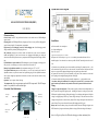
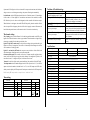
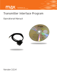
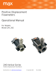
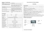
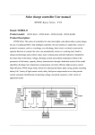
 Day‐Light System Charge Controller Wiring Diagram & Manual If you have any questions please contact: RenCon Energy Products, Inc. 472 Moore Lane, Healdsburg, CA 95448 (800) 601‐[email protected] www.renconenergy.com System main circuit diagram
SOLAR POWER CONTROLLER(SDRC)
USER MANUAL
Characteristics:
Control circuit: use MCU and professional software as the control center to fulfill intelligent
system control.
Charging mode: use PWM high efficiency charging way. Boost, recovery and float charging auto
work for battery long-life. Use temperature compensation.
High accuracy over discharging control by the discharging rate: Over-discharging control
voltage modified by the battery discharging rate curve.
Self protection: protection to overload, outside and inside short circuit, reverse connection,
thunder and lightning, PV panel reverse current, over charging and discharging etc. during the
short circuit and overload protection, no any component will be damaged and need change, include
fuse.
LED indication on system condition: LED indicating the system of charging, overcharge, power
full, power low, over-discharge, over load, out short circuit, load on/off, etc.
Industry level production standard: wide temperature running area -35℃ to +50℃
No adjustable hardware part: use flash memory to save all work control point instead of
adjustable resistance, to protect the control work point from going off as the adjustable resistance
value is easily changed by temperature and vibration, in order to make sure the control accuracy
and reliability.
Operation: easy to operate, robust in design.
Two output modes: direct current output mode and 1HZ output mode. The1HZ output
suitable length of wire and make it as shout as possible. Peel off 5mm the plastic at the end of
mode is very suitable for traffic caution light.
Using:
Controller Panel Indications
Charge & overpressure indication:If the system is properly connected ,when sunlight shines on
Installation:
a. fix the controller in a certain place .
size of the installing hole :
Size: 140 ×90.5(mm)
Length between installing holes:133.5×70(mm)
b. Prepare wire. Choose the plastic Copper wire. Current density no more than 4A/mm2. Cut the
wire.
c. Connect the wire to the battery port on the controller to the battery. Pay attention to the +, - pole
of the connection. If the pole is reverse, it does not work. It has the function of self protection, and
there is no any part will be damaged during this step, but should correct this mistake.
d. Connect the wire to the PV port on the controller to PV panel. If the connection is correct and
the PV panel gets the sunlight, charging indicator will be light.
e. Connect the load to the load port on the controller. Attention the +, - pole should be correct.
!! Attention: during the installation, if the voltage of the system is 24V, you can not use the
hands to touch any conductor in the system circuit in order to protect from electric shock.
the PV panel ,the charge LED lights in green,indicating the system is working in a good order.
PV charge
Work mode
PWM mode is applied in charging. During the charging, if over discharge has happened, firstly the
LED(1)
Digit set key
voltage for charging battery will be up to boost voltage and keep 10 mins, then returns to direct
voltage and keep 10 mins to activate battery, lastly to float voltage and keep this state for the best
System state
ON/OFF
LED(2)
Button
state of battery. These process is benefit to battery full charging and its life -span.
Battery state: when the battery voltage is in normal condition, the state LED lights in green; state
LED flashes slowly in green when battery finishes its charge; When the voltage of the battery is
Short circuit
LED(3)
lower, it will get in yellow color. When the voltage goes down continuously the
+-+-+-
PV
Bat
Load
1
1
2
System state LED will get in red color, and turns off the output at the same time, until the battery
Problems & Troubleshooting:
voltage recovers to over discharge return voltage, the system will work again automatically.
Problems
The charge LED indicator doesn’t light in
green when sunlight gets the PV panel.
The charge LED indicator flash quickly .
Load indication: the load LED lights when the load works. If the load current is 1.25 times higher
for 60 seconds or 1.5 times higher for 5 seconds than rated current of the controller, the trouble
LED flash slowly in red to show overload happened, and the controller will shut down output.
load at fault and press the button, it will resume its work in 30 seconds or in another day.
The load LED indicator light but there is no
power output.
The load LED indicator flash quickly and
there is no power output .
Work mode setting:
The load LED indicator light slowly and
there is no power output.
When load short circuit happens, the trouble LED will flash quickly, then the controller will shut
down its output. When it happens, please check if the load is properly connected. Disconnect the
Way of setting: press the on & off button for 5 seconds long until the number on the LED screen
begins to flash. Press the button to choose a proper number. When the number no longer flashes,
the setting is completed. Press the button to check the value.
Light ON+ Light OFF control mode: The load will start working when it gets dark until it gets
bright or to the end of a setting time. There will be a 10 mins delay before turning on the load in
order to make sure if it really gets dark.
Light ON + set time delay OFF mode: the start process same with above. Load will be closed
after the setting time. Setting time can be seen in time setting table.
Common controller mode: The controller will work as a common controller, no light and time
control, no ON and OFF delay time. only has the else function. If no sunlight on PV panel, it will
turn on load at once; If sunlight on PV panel, it will turn off load at once.
Test mode: It used for the Light control system installed test. Only cancel the ON and OFF delay
Two Output modes: when the number displayed on the LED is anyone from 1 to 7, it is in Direct
System state LED indicator flash in red
color and there is no power output.
Type
SDRC5(I)
SDRC-10(I)
SDRC-15(I)
5A
10A
15A
Rated load current
5A
10A
15A
Over load, short circuit
protection
≤6mA
Charging circuit voltage drop
≤0.26 V
Forbid using 1HZ output mode on capacitive or inductive load.
Work temperature
LED
Light ON+ Light OFF
0
0.
Light ON +10 Hour delay OFF
4
4.
Light ON + 4Hours delay OFF
1
1.
Light ON +12Hours delay OFF
5
5.
Light ON + 6Hours delay OFF
2
2..
Common controller
6
6.
Light ON + 8Hours delay OFF
output mode
3
DC
3.
1HZ
Test(no delay)
output mode
7
7.
DC
1HZ
≤0.15 V
17V; ×2/24V
-
Industry stage: 35℃ to +55℃;
Boost charge voltage
14.6V;×2/24V; (keep 10min)
Direct charge voltage
14.4V; ×2/24V; (keep 10min)
Float charge voltage
13.6V; ×2/24V;
charge return voltage
13.2v;×2/24V;
Temperature compensation
-5mv/℃/cell (Boost charge, Direct charge, Float charge, charge return voltage);
Lower voltage indicate
12.0V; ×2/24V;
Over discharge voltage
11.1V(no load)- real-time modified voltage by the discharge rate; ×2/24V;
12.6V; ×2/24V
Over discharge return voltage
Control mode
3
1.25 rated load current 60sec, 1.5 rated loads current 5sec, over load protection
action. ≥3 Rated load current short circuit protection action.
No load current
Over voltage protection
Work mode
□12v; □12/24V Auto
Work voltage
Load circuit voltage drop
LED
Check output circuit .If the load short or over load
occurs, remove the load and push the button and the
controller will resume its work after 30 minutes.
Overload occurs, remove some loads and push the
button again and the controller will resume its work
after 30 minutes.
Over discharge of the battery. The controller will
resume its work after finishing charge of the
battery.
Rated charge current
directly started to display the 1HZ output mode. Start the pure resistance load in 1HZ output mode.
Work mode
System over voltage or open circuit of the battery.
check if the battery connects to the system cable
properly or the charging circuit damaged.
Check if the load connects to the system properly.
Specifications:
output mode; when the number is decimal from 0.1 to 7.0, it is in 1HZ output mode. LED can be
Time setting:
Troubleshooting
Check if the cable of solar panel connects properly.
PWM charge mode; modified discharge voltage by the discharge rate
4