1
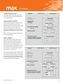
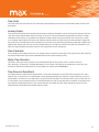
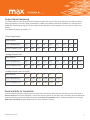
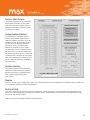
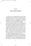
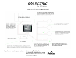
an ISO 9001:2008 certified company
Transmitter Interface Program
Operational Manual
Version 3.0.4
SE-M-001 Version 3.0.4
1
an ISO 9001:2008 certified company
Overview
The transmitter interface software allows you to adjust configuration settings of your Max solid state transmitters.
The following settings can be accessed and modified: Pulse Output Scaling, Analog Output Limits and Scaling, Signal
Filtering Options and Compensation settings.
To use the serial interface, an interface kit can be purchased from the factory (Max Part # 294-100-050). This includes
the installation CD and a special cable to connect the transmitter to the USB or serial port of a PC.
Software Installation Procedure
This program is built off of Labview’s runtime library. It is designed only for Windows 2000, Windows XP, Vista or
Windows 7. Also, a minimum of 128 MB of RAM, at least 100 MB of available disk space, and a screen resolution of at least
800 x 600 pixels is required.
While it is acceptable to have multiple versions of the runtime library and the Max Transmitter program installed on the
same computer, it is preferred that old versions be removed before installing the latest revision.
To remove the old versions:
Click on Start, Settings, then Control Panel.
Double Click Add or Remove Programs - Find either Max294 or MaxXmtr and click on it.
Click on Remove and follow the on screen instructions.
To remove the National Instruments runtime components, select National Instruments Software, Click on Remove and at the pop up window select Ni-Visa Runtime and Remove.
SE-M-001 Version 3.0.4
2
an ISO 9001:2008 certified company
Now you can complete the following steps to install the latest version of this program
1. Disable any automatic virus detection programs and exit all applications before running this installer.
2. Insert the MaxXmtr Serial Interface Program installation CD and follow the instructions on the screen.
3. If your PC has the Auto Run feature disabled, the SETUP.EXE program can be started from either Windows Explorer
or by the following sequence:
a. Click on Start then click on Run.
b. Select Browse - Find the installation CD and double click Setup.exe.
4. After the installation is complete, re-enable any virus detection programs you may have disabled.
5. To run the Serial Interface Program, press Start, All Programs, then find MaxXmtr\MaxXmtr and click.
6. If any problems occur, reboot, and follow the removal instructions above. Then reboot and attempt the install again.
If the problem persists, please contact Max Machinery.
Starting the Interface Program
1. Remove the lid of the transmitter to reveal 1/8” serial port. See the transmitter’s user manual for assistance.
2. Next, insert the 1/8” serial plug into the connector on the transmitter circuit board.
3. Connect the serial cable to the serial port on the PC. If your computer does not have any form of serial port, then
the USB to serial adapter can be used.
To use the USB port you must first install the proper driver on your computer. Please refer to the “Readme” file
on the CD before using the USB adapter
4. Ensure the transmitter is powered up, and launch the MaxXmtr Interface Program by either selecting MaxXmtr from
the start menu, or by double-clicking on the MaxXmtr executable located in the installation directory.
A dialog box will prompt the user to select the serial port. Choose the port to which you have connected the
serial interface cable and press Continue.
If the transmitter is not detected, an error message will be displayed. Verify that the transmitter is connected to
the serial cable and powered up, then press Retry. A red or green LED should be lit on the transmitter circuit
board if it has power.
If the wrong serial port was selected by mistake, the MaxXmtr program will need to be closed and restarted with
the correct serial port indicated.
If the connection is not successful, contact your Max Sales Representative for assistance.
Once serial communication is established, the program will automatically read the transmitter data and display the
software version on the Information screen.
SE-M-001 Version 3.0.4
3
an ISO 9001:2008 certified company
Screenshots
To print screen shots of the program use your computer’s built in Print Screen function. Simply have the MaxXmtr program
active and press <Alt> <PrintScreen> on the keyboard. This will copy the current window to the clipboard which may then be
pasted in to Microsoft® Word or other document programs.
Program Compatibility
The program is designed to work with all current and previous versions of the Max Model 269 and 290 Series transmitters.
After reading the data out of the transmitter, the appropriate fields will be active and the other fields will be grayed out or
hidden.
Additionally, certain fields can only be changed by entering a factory password. In limited cases, mainly when doing a field
replacement of a new transmitter on an old meter, the factory fields may need to be accessed by the customer. In these
cases contact the factory or your local sales representative for details.
Interface Simulator Mode
A simulation mode may be accessed by starting the program without any connection to a physical transmitter. When
prompted to select a serial port, choose any unused port and when prompted by Transmitter Not Detected, select Cancel.
Then select OK to run in simulator mode. This allows you to tryout the functionality of both pulse and analog transmitters
without needing to physically connect to a transmitter.
SE-M-001 Version 3.0.4
4
an ISO 9001:2008 certified company
Output Data Screen
The Output Data tab provides access to
the most commonly adjusted parameters
for the transmitter.
Linearization On/Off
This feature corrects for mechanical nonlinearity of the meter to produce an
output signal that is precisely proportional
to flow. Typically the only reason to
turn off linearization is to collect the
calibration data with which to populate
the linearization table on the factory data
tab.
Note: on analog transmitters this feature
cannot be disabled.
Pulse Output
With linearization enabled the meter’s
output can be set to a precise Output
K-Factor where each pulse represents a
fixed volume. This allows the user to
take several meters and set them all to an
exact scaling. With Linearization off, you
are able to set a fixed number of pulses
per revolution of the meter.
Note: (for quadrature output transmitters)
the Output K-Factor shown is the output
on one of the channels (phase A OR phase
B) however the meter’s total resolution is
the total number of pulses output on both
channels (phase A PLUS phase B).
SE-M-001 Version 3.0.4
5
an ISO 9001:2008 certified company
Flow Units
This field shows the units used for the Transmitter Output Settings as well as the Linearization Data stored on the
transmitter.
Analog Output
This sets both the output limits and the output scaling. Voltage transmitters can be set anywhere between -10V and
+10V, and current transmitters within the range of -20 mA to +20 mA. Because the transmitter receives a 2 stage
calibration at the factory, it is possible to change the analog scaling at any time without loss of accuracy or need
to re-calibrate. Note that the minimum and maximum output values are hard limits that the transmitter output will
not exceed. The Flow Minimum and Flow Maximum can be set to any desired measurement range both negative and
positive (the output span can even be set to a tight band such as 200 ccm minimum and 250 ccm maximum if you
want very high resolution and have a specific flow range that you are measuring).
Flow Calculator
This is simply a tool to allow the user to run sample values of either the flow rate or the output value. After entering
one field, the alternate field is then calculated based on the chosen analog scaling.
Meter Flow Direction
This field is set by the factory based on the mechanical design of each meter (CCW = counter clockwise,
CW=clockwise). If the meter is installed backwards for any reason, this field can be switched to correct any sign
reversal. If bidirectional measurement is not needed, this may be set to All Positive.
Flow Reversal Dead Band
On meters without a bidirectional output, there is a risk that momentary reverse flow will be output as if it was a
positive flow. To prevent this, the transmitter can be programmed with up to 100% of 1 meter revolution to act as
a dead band. For instance if you select 50%, any flow reversal that does not cause the meter to turn more than 1/2
of a revolution in the reverse direction will be buffered and only net forward flow will be counted. If the meter turns
more than the dead band amount in the reverse direction, the meter will then begin reporting reverse flow. For
unidirectional configurations the default setting is 50%.
SE-M-001 Version 3.0.4
6
an ISO 9001:2008 certified company
Output Signal Dampening
This feature sets the time constant/cut-off frequency used to filter the raw flow signal. Selecting zero will turn off the
filtering completely. The zero setting can be useful if sudden flow changes need to be measured, or if filtering will be
added after measuring the signal. The time constants and equivalent cut-off frequency for each type of meter are as
follows:
(The default setting for all models is 5)
Pulse Output chart
Filter Setting
1
2
3
4
5
6
7
8
9
Time Constant (ms)
0.6
1.7
3.7
7.8
15.6
31.3
62.5
125
250
Cut-off Frequency (Hz)
1700
600
270
128
64
32
16
8
4
Filter Setting
0
1
2
3
4
5
6
7
8
9
Time Constant (ms)
0.6
3.7
7.8
15.6
31.3
62.5
125
250
500
1 sec
Cut-off Frequency (Hz)
600
270
128
64
32
16
8
4
2
1
Analog Output chart
Analog Output chart (continued)
Filter Setting
10
11
12
13
14
15
Time Constant (ms)
2 sec
4 sec
8 sec
16 sec
32 sec
64 sec
Cut-off Frequency (Hz)
0.5
0.25
0.125
0.062
0.031
0.015
Read and Write to Transmitter
These two buttons allow for reading from or writing to the transmitter. After entering new data into any of the fields, a
Data Changed prompt will be displayed. If you wish to save any entries or selections you have made, you must download
those new settings into the transmitter by pressing the Write to Transmitter button. To discard changes you can select
Read from Transmitter to again upload what is in the transmitter memory.
SE-M-001 Version 3.0.4
7
an ISO 9001:2008 certified company
Factory Data Screen
The Factory Data tab shows calibration
settings that generally will only need
to be set at the factory. Most fields are
password protected. If needed, contact
the factory for details.
Compensation Options
Compensation is a software feature
where the transmitter measures the
rotational speed of the meter thru one
complete revolution, and then corrects
for this variation. Because different
mechanical meters contain design
differences resulting in cyclic speed
variation, this process is able to smooth
out this cyclic error without adding any
signal filtering. Note that it is critical that
a constant flow is passing thru the meter
when this compensation is done so that
only mechanical variation is mapped by
the transmitter.
Restore Factory
This option restores the compensation
table to the values that were originally
learned at the factory. Generally used
after a field compensation yields
poor results.
Disable
This turns off the cyclic compensation and is only recommended for a field replacement transmitter when a steady flow
is not available to perform a field compensation.
Perform Field
This option characterizes the flow meter and sensors at a steady flow rate to provide optimal spacing of the output
pulses. Use when optimal output response is needed, Factory Compensation is not available or the application is very
low flow or high viscosity fluid.
Note: You must have a steady flow during compensation.
SE-M-001 Version 3.0.4
8
an ISO 9001:2008 certified company
Perform Factory
The option is used only by the factory for initial compensation.
Requirements for Field Compensation
Recommended Meter RPM
Minimum Acceptable RPM
Maximum Acceptable RPM
Maximum Allowable Flow Ripple
15 - 1000
10 (LOW FLOW error displayed if lower)
1350 (HIGH FLOW error displayed if higher)
3% (or UNSTEADY FLOW error displayed)
Activating Selected Compensation
After selecting the desired compensation option, the Proceed with Option button must be pressed. This initiates the
compensation, during which the Status Bar will turn yellow (In Progress, may take up to 1 minute). Upon completion the
Status Bar will turn grey and display the results of the compensation.
Linearization Data
The displayed values are from the Raw Factory Calibration of a flow meter. They are NOT the values shown on the
Calibration Certificate provided with the flow meter. Typically, the linearization table is programmed into the
transmitter/meter assembly at the factory and will not need to be modified by the user, except in the following cases:
a)
After performing a field calibration of the flow meter.
b)
During a field replacement of the transmitter where the customer wishes to enter the linearization data.
In this case you must request the Raw Factory Calibration Report be sent to you for the flow meter (the flow meter serial number is required) or note the values entered into the original transmitter’s
linearization data fields. The factory can also load K-factor data into a replacement transmitter before
shipment.
Analog Calibration
This data is collected on analog transmitters using high accuracy measurement equipment and provides precise
calibration of the onboard circuitry.
Note: Do not make changes in this area. A loss of “cal“ and “result“ data will shut off the analog output signal.
Contact Us
If you need further assistance, e-mail [email protected] or call 707.433.2662
SE-M-001 Version 3.0.4
Max Machinery, Inc.
maxmachinery.com
33A Healdsburg Avenue
T + 1 707.433.2662
Healdsburg, CA 95448
F + 1 707.433.1818
9