1
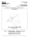
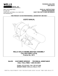
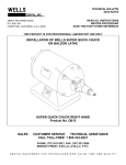
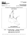
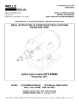
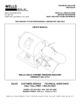
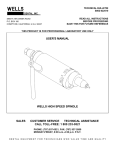
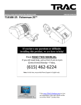
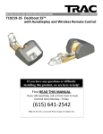
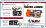
TECHNICAL BULLETIN
Q825-022510
DENTAL, INC.
5860 FLYNN CREEK ROAD
P.O. BOX 106
COMPTCHE, CALIFORNIA, U.S.A. 95427
www.wellsdental.com
READ ALL INSTRUCTIONS
BEFORE PROCEEDING
SAVE THIS FOR FUTURE REFERENCE
THIS PRODUCT IS FOR PROFESSIONAL LABORATORY USE ONLY
INSTALLATION OF WELLS SUPER QUICK CHUCK
ON RED WING LATHE
RED WING ADAPTER KIT
Product No. Q206
SALES
CUSTOMER SERVICE
TECHNICAL ASSISTANCE
CALL TOLL-FREE: 1 800 233-0521
PHONE: (707) 937-0521, FAX: (707) 937-2809
MONDAY-FRIDAY, 8:00 a.m.-4:30 p.m. P.S.T.
DENTAL EQUIPMENT FOR TECHNICIANS WHO VALUE TIME AND QUALITY
INSTALLATION OF WELLS SUPER QUICK CHUCK ON RED WING LATHE
1.0
MATERIALS REQUIRED
1.1
1.2
PAGE 2
The Red Wing lathe should be in good running condition. If it has noisy bearings, a worn switch, starting problems or
excessive end play (greater than 1/32"), the condition should be corrected before proceeding with the installation.
The condition of the tapered shaft is not important because it is not used.
A Q015 SUPER QUICK CHUCK RIGHT HAND and a Q206 ADAPTER RED WING are required. See Figure 1.
Figure 1. Materials
2.0
TOOLS NEEDED
1/4" straight blade screwdriver
9/16" socket or end wrench
3/8" socket or end wrench
Pair of pliers
File
Rule
Figure 2. Tools
3.0
REMOVE THE RIGHT SIDE THROW-OFF
UNPLUG THE POWER CORD. Remove the red plastic
hub cover and unscrew the right side throw-off. See Figure
3. If the throw-off is in two pieces, REMOVE THE SET
SCREW in the hub with the 3/32 hex wrench and remove
the male threaded portion.
Figure 3. Right side throw-off
Q825-022510
WELLS DENTAL, INC.
INSTALLATION OF WELLS SUPER QUICK CHUCK ON RED WING LATHE
4.0
DETERMINE THE SHAFT END PLAY
4.1
4.2
4.3
4.4
Put a thickly folded shop towel in the palm of your hand and
push firmly (50 lbs force) on the right end of the shaft. If
any movement is detected in this direction, the lathe must
be dismantled and the spring washer moved from the left
side to the right side; go directly to step 5.0.
Push on the left end while measuring the protrusion of the
shaft. See Figure 4. You may need an assistant to push
the shaft while you measure. If the end play is greater than
1/32" the lathe should be shimmed; go to step 5.0.
If there is NO end play from either the right or the left end,
the bearing journals are frozen; go to step 5.0.
If the end play is 1/32" or less when the LEFT end of the
shaft is pushed, the end play is OK; skip step 5.0 and go to
step 6.0.
PAGE 3
Figure 4. Shaft end play
5.0
DISASSEMBLE AND SERVICE THE LATHE
5.1
5.2
5.3
5.4
5.5
5.6
CHECK THAT THE POWER CORD IS UNPLUGGED.
Turn the lathe upside down and remove the four base plate screws, rubber feet and base plate. See Figure 5.
LOOSEN the two right side base bolt(s).
REMOVE the two left side base bolt(s) and lock washers.
Remove the four nuts on the thru-bolts.
Tap the rim of the left end bell with a screwdriver and hammer to loosen it. Remove the end bell but do not remove
the rotor at this time. Remove all the washers from the left side of the rotor. They may be on the shaft, stuck to the
left side bearing or inside the end bell. Keep the left side washers with the left end bell.
Carefully remove the rotor then remove all the washers from the right side. They may have fallen between the right
end bell and the stator. They may be on the shaft, stuck to the right side bearing or inside the end bell. Keep the right
side washers with the right end bell.
Clean the grease and dirt from the rotor and end bells paying particular attention to the outside bearing surfaces and
inside the end bells where they rest. Check that the bearings slide freely in each end bell. If necessary, polish the
outside of the bearings and the inside of the end bells with emery cloth.
IMPORTANT: If the SPRING WASHER is on the left side, move it to the right side and move ONE SPACING
WASHER from the right side to the left side in exchange.
Apply a very thin film of grease to the outside of the bearings, the washers and the inside of the end bells.
Install the spacing washers for the right side into the right end bell. Install the spring washer last so it will be next to
the bearing. NOTE: If you have a finger type spring washer, the fingers must face TOWARD the bearing.
Carefully install the rotor into the right end bell paying particular attention to the wires and internal starting switches.
Install the spacing washers for the left side into the left end bell. NOTE: There should be no spring washer on the left
side.
Install the left end bell. Rotate the end bell to align the thru-bolts. Start the nuts onto the four thru-bolts and tighten in
an alternating pattern so that the end bells are pulled together evenly.
Check the shaft end play as in step 4.2. There should be detectable end play less than 1/32" when pressure is
applied to the left end of the shaft. If there is excessive end play, an additional spacing washer needs to be installed
on the left side.
Rotate the shaft by hand. It should spin freely.
Install the two left side base bolts and lock washers and tighten all four base bolts.
Install the base plate and the four rubber feet with the base plate screws.
Plug in the power cord and check that the lathe starts and runs properly on both high and low speeds.
5.7
5.8
5.9
5.10
5.11
5.12
5.13
5.14
5.15
5.16
5.17
5.18
5.19
Q825-022510
WELLS DENTAL, INC.
INSTALLATION OF WELLS SUPER QUICK CHUCK ON RED WING LATHE
PAGE 4
Figure 5. Exploded view of the Red Wing lathe
6.0
PREPARE THE HUB AND SHAFT
6.1
6.2
CHECK THAT THE POWER CORD IS UNPLUGGED.
Scrape and clean all the paint from the lathe hub. File the
hub smooth if necessary so the adapter will slide on.
Remove burrs from the 1/2" dia. shaft with the emery cloth.
Hold the left end of the shaft wrapped in a shop towel with
the pliers. File a flat on the shaft where the clutch set screw
contacts the shaft. See Figure 6.
The clutch should slide into place without binding. Use the
emery cloth to remove any high spots.
6.3
6.4
6.5
Figure 6. Hub and shaft
Q825-022510
WELLS DENTAL, INC.
INSTALLATION OF WELLS SUPER QUICK CHUCK ON RED WING LATHE
7.0
INSTALL THE CLUTCH
7.1
7.2
PAGE 5
With the fiber side of the clutch facing away from the lathe,
slide it onto the shaft until it stops. Measure the clearance
between the hub and the clutch. See Figure 7. If it is less
than 1/16", remove the clutch and install the thinner gold
spacer. Recheck the clearance. If it is still less than 1/16",
remove the gold spacer and try the blue one. If the
clearance is still less than 1/16" install both spacers.
Put a very thin film of grease on the shaft and install the
clutch so the set screw will tighten on the flat that was filed.
Hold the clutch all the way on and tighten the set screw
securely. Recheck the clearance.
Figure 7. Clutch position
8.0
INSTALL THE ADAPTER
8.1
8.2
Loosen the two clamp screws on the adapter.
Position the adapter with the clamp screws in the rear. The slot should
face down at a 45 degree angle. See Figure 8. The screw holes for the
Quick Chuck should be aligned vertically and horizontally.
Using a block of wood to protect the adapter, tap the face of the adapter
on alternate sides until the clutch face is recessed 5/16" from the end of
the adapter. See Figure 9.
Temporarily tighten one of the clamp screws just enough to hold the
adapter firmly.
8.3
Figure 8. Right end view
8.4
Figure 9. Clutch recess
9.0
INSTALL THE QUICK CHUCK
9.1
Confirm the Quick Chuck
handle is in the shipping
position. See Figure 11.
Temporarily fasten the Quick
Chuck to the adapter with two
opposing screws.
9.2
Figure 10. Adapter ready for Quick Chuck
Q825-022510
WELLS DENTAL, INC.
INSTALLATION OF WELLS SUPER QUICK CHUCK ON RED WING LATHE
10.0
ADJUST THE HANDLE POSITION
The Quick Chuck handle position must be correctly
adjusted for proper operation. This is done by
moving the adapter toward or away from the lathe.
10.1
10.2
10.3
10.4
10.5
10.6
10.7
10.8
10.9
PAGE 6
Make sure the shipping rod (or a 3/32" shanked tool)
is in the collet. Slowly move the handle clockwise
until it comes to rest.
If the handle stops PAST 9:30, the adapter must be
moved toward the lathe. Move the handle back to
the shipping position and remove the Quick Chuck.
Loosen the clamp screws. Note the amount of gap
between the adapter and lathe. See Figure 11.
Using a block of wood to protect the adapter, tap the
face of the adapter on alternate sides to move the
adapter a little closer to the lathe (1/32" less gap).
Temporarily tighten one of the clamp screws and
fasten the Quick Chuck to the adapter with two
opposing screws. Repeat step 10.1.
If the handle stops BEFORE 9:30, the adapter must Figure 11. Handle position
be moved away from the lathe. Loosen the clamp
screws. Note the amount of gap between the adapter and lathe. See Figure 11. Pry between the adapter and lathe
on alternate sides to move the adapter a little further from the lathe (1/32" more gap). It may be necessary to wedge
a screwdriver into the slot in the adapter to enlarge it. Temporarily tighten one of the clamp screws. Repeat step
10.1.
If the handle stops at 9:30, the adapter is correctly positioned. Tighten both clamp screws.
Fasten the Quick Chuck with all four installation screws and tighten securely.
Move the handle to the open collet position and start the lathe. If the Quick Chuck runs with no excessive noise, go to
step 10.7. If there is excessive noise, stop the lathe and remove the Quick Chuck. Start the lathe with no Quick
Chuck. If the noise persists, stop the lathe, remove the adapter and start again at paragraph 7.0. Make sure there is
1/16" clearance between the clutch and hub and the set screw is tight. If there is no noise when the Quick Chuck
removed, the lathe shaft is probably rubbing on the inside of the Quick Chuck shaft due to mis-alignment of the
adapter. Loosen the clamp screws and pry between the adapter and the lathe so the gap is the same all the way
around. Tighten the clamp screws and fasten the Quick Chuck with the four installation screws and tighten securely.
If the noise still persists, the lathe shaft can be cut off with a hack saw where it steps down to the taper.
With the shipping rod or tool in the collet, move the handle to the operating position and check that it rests at 9:30.
Turn off the lathe. Tighten the two clamp screws, first one, then the other alternating several times until the screws
are TIGHT. Check that the four installation screws are secure.
Tighten the adapter set screw with the 3/32 hex wrench.
CONGRATULATIONS! This completes the installation of the WELLS Super Quick Chuck.
If you have any questions or problems, please call us at 1-800-233-0521. We will be happy to help you.
IMPORTANT: READ ALL INSTRUCTIONS IN THE USER'S MANUAL BEFORE OPERATING.
Q825-022510
WELLS DENTAL, INC.
INSTALLATION OF WELLS SUPER QUICK CHUCK ON RED WING LATHE
PAGE 7
NOTES
Q825-022510
WELLS DENTAL, INC.
INSTALLATION OF WELLS SUPER QUICK CHUCK ON RED WING LATHE
PAGE 8
NOTES
Q825-022510
WELLS DENTAL, INC.