1
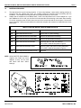
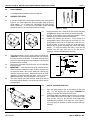
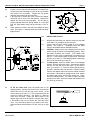
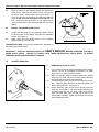
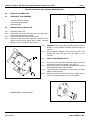
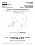
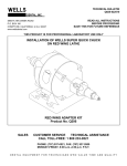
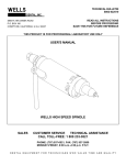
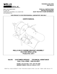
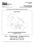
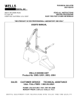
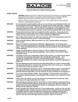
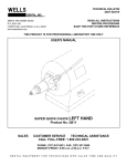
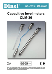
TECHNICAL BULLETIN
Q833-022510
DENTAL, INC.
5860 FLYNN CREEK ROAD
P.O. BOX 106
COMPTCHE, CALIFORNIA, U.S.A. 95427
READ ALL INSTRUCTIONS
BEFORE PROCEEDING
SAVE THIS FOR FUTURE REFERENCE
THIS PRODUCT IS FOR PROFESSIONAL LABORATORY USE ONLY
INSTALLATION OF WELLS SUPER QUICK CHUCK
ON BALDOR LATHE
SUPER QUICK CHUCK RIGHT HAND
Product No. Q015
SALES
CUSTOMER SERVICE
TECHNICAL ASSISTANCE
CALL TOLL-FREE: 1 800 233-0521
PHONE: (707) 937-0521, FAX: (707) 937-2809
MONDAY-FRIDAY, 8:00 a.m.-4:30 p.m. P.S.T.
DENTAL EQUIPMENT FOR TECHNICIANS WHO VALUE TIME AND QUALITY
INSTALLATION OF WELLS SUPER QUICK CHUCK ON BALDOR LATHE
PAGE 2
1.0
MATERIALS REQUIRED
1.1
The lathe should be in good running condition. If it has noisy bearings, a worn switch, starting problems or
excessive end play (greater than 1/32"), the condition should be corrected before proceeding with the
installation. The condition of the tapered shaft is not important because it is not used.
Adapter kits are available for most Baldor lathes. Refer to the table below for the correct adapter kit. If you
have a Baldor No. 221 or 240, you must find out if it has the older 35mm bearing or the newer 40mm bearing.
To do this, unplug the power cord first, then remove the four screws that hold the chuck ejector. Remove the
ejector assembly. Remove a steel washer from inside the end plate and measure its outside diameter for the
bearing size.
1.2
WELLS SUPER QUICK CHUCK ADAPTER KITS
Part No. Description
Fits these lathes.
Q209
ADAPTER BALDOR 210/211
Baldor 210 & 211 (35mm bearing)
Q212
ADAPTER BALDOR 221/240 35MM
Baldor 221 & 240 with 35mm bearing
Q215
ADAPTER BALDOR 221/240 40MM
Baldor 221 & 240 with 40mm bearing
Q218
ADAPTER BALDOR 300 SERIES
Baldor 350, 353, 357, 359, 370, 380 and
350T or 353T if it has the end plate in Figure 5.
Q237
ADAPTER BALDOR END PLATE
Baldor 357T,359T,380T,WELLS R051,R052,R053
350T or 353T if it has the end plate in Figure 4.
Q239
ADAPTER BALDOR 340 END PLATE
Baldor 340
For others, call Wells Dental, Inc.
NOTE: Q508 ADAPTER RING 40MM is
supplied with Q209 and Q212
adapters so they can be used
with lathes that have 40mm
bearings.
Figure 1.
Figure 2. Materials
Q833-022510
WELLS DENTAL, INC.
INSTALLATION OF WELLS SUPER QUICK CHUCK ON BALDOR LATHE
2.0
PAGE 3
TOOLS NEEDED
1/4" straight blade screwdriver, pliers, file and rule
3.0
PREPARE THE LATHE
3.1
If you have a lathe with a chuck ejector similar to the one pictured in
Figure 4, you must replace the whole end plate using a Q237 or
Q239 adapter. Go to section 8.0, REPLACE THE END PLATE,
before continuing. If you have the removable ejector assembly
pictured in Figure 5, you may continue to the next step.
3.2
3.3
3.4
Figure 4.
3.5
3.6
3.7
3.8
Figure 5.
Figure 3. Tools
Unplug the power cord. Remove the four screws that hold
the right chuck ejector and remove the ejector assembly.
Remove all the washers from inside the end plate. Some
washers may be stuck to the ejector assembly.
Examine the washers you removed. If one of them is a
spring washer (wavy or finger type) go on to step 3.5. If no
spring washer was found on the right side of the rotor, it is
on the left side. It must be moved over to the right side.
Remove the left ejector assembly and remove the spring
washer. To keep the spacing the same, move two flat
washers from the right side over to the left side in
exchange. Replace the left ejector assembly.
Check that the shaft is free to move at least 1/8" end to end.
CAUTION: Do not move the shaft more than 1/8" because
the rotor could fall out of place. If the shaft does not move
end to end, the bearings are frozen inside the end plate and
the lathe must be serviced.
Remove any rust, paint or burrs from the 1/2" dia. shaft with
the emery cloth.
IMPORTANT: A flat must be filed on the shaft where the
clutch set screw contacts the shaft. If this is not done, the
set screw will raise a burr on the shaft and it will be very
difficult to remove the clutch. Hold the left end of the shaft
wrapped in a shop towel with the pliers. File a flat on the
right shaft about 3/8" from the end plate. See Figure 6.
The clutch should slide freely onto the shaft all the way to
the bearing without binding. Use the emery cloth to remove
any high spots.
Figure 6. Flat for set screw
4.0
ADJUST THE SHAFT END PLAY
4.1
Place the spring washer next to the bearing on the right
side. If it has fingers, face the fingers TOWARD the
bearing. Leave the other washers out for now.
Temporarily attach the adapter with two 10-32 x 1/2 screws.
Put a folded shop towel in the palm of your hand a push
firmly (50 lbs. force) on the left end of the shaft while
measuring the protrusion of the right end. See Figure 7.
You may need an assistant to push the shaft while you
measure.
4.2
Figure 7. Shaft end play
Q833-022510
WELLS DENTAL, INC.
INSTALLATION OF WELLS SUPER QUICK CHUCK ON BALDOR LATHE
4.3
4.4
4.5
PAGE 4
If there is no end play and the shaft does not rotate freely,
remove the ejector assembly from the left end of the lathe
and remove one flat washer. Replace the left ejector
assembly and measure the end play again.
If the end play is greater than 1/32", remove the adapter
and install one or more of the flat washers. Replace the
adapter and check the end play again. The end play is
properly adjusted when the spring washer is on the right
side, the shaft rotates freely and the end play is 1/32" or
less.
Check that the 1/4" hole in the side of the adapter is facing
down. See Figure 9. Install the other two screws and firmly
tighten all four.
Figure 8. Handle position
5.0
INSTALL THE CLUTCH
5.1
With the fiber side facing out, slide the clutch onto the shaft
until it stops. Do not tighten the set screw yet.
Confirm that the Quick Chuck handle is in the shipping
position. See Figure 8. Temporarily fasten the Quick
Chuck to the adapter with two installation screws.
CAUTION: Always have a tool or shipping rod in the collet
before moving the handle to the operating position. Move
the handle clockwise until it stops. If the handle rests
between 9:15 and 10:00, no adjustment is necessary; go to
step 5.6. If the handle position is higher than 10:00, add
spacers; go to step 5.4. If the handle position is lower than
9:15, file the clutch hub; go to step 5.5.
To add spacers, move the handle back to the shipping
position. Remove the Quick Chuck. Insert the hex wrench
into the 1/4" hole and pry out the clutch. (If the clutch is
stuck, go to step 7.1.1.) Place the thinner gold spacer on
the shaft. Slide the clutch onto the shaft. Fasten the Quick
Chuck to the adapter again and move the handle clockwise
until it stops. If the handle is still higher than 10:00, replace
the thinner gold spacer with the blue thicker one. Again,
check the handle position. If it is still too high, place both
spacers on the shaft. When the handle rests between 9:15
and 10:00, go to step 5.6.
5.2
5.3
5.4
Figure 9. Cross section view
5.5
To file the clutch hub, move the handle back to the
shipping position. Remove the Quick Chuck. Insert the hex
wrench into the 1/4" hole and pry out the clutch. (If the
clutch is stuck, go to step 7.1.1.) File or grind the end of the
clutch hub a little to shorten it. See Figure 10. Slide the
clutch onto the shaft. Fasten the Quick Chuck to the
adapter again and move the handle clockwise until it stops.
If the handle is still too low, shorten the clutch hub some
more. You must add a spacer if you shorten it too much.
When the handle rests between 9:15 and 10:00, go to step
5.6.
Q833-022510
Figure 10.
WELLS DENTAL, INC.
INSTALLATION OF WELLS SUPER QUICK CHUCK ON BALDOR LATHE
5.6
Move the handle to the shipping position and remove the
Quick Chuck. Insert the hex wrench into the 1/4" hole and
pry out the clutch. (If the clutch is stuck, go to step 7.1.1.)
Put a very thin film of grease on the shaft and install the
clutch so the set screw will tighten on the flat that was
filed. Hold the clutch all the way on and tighten the set
screw securely with the hex wrench through the hole in the
adapter.
6.0
INSTALL THE SUPER QUICK CHUCK
6.1
Confirm that the handle is in the shipping position. Fasten
the Quick Chuck to the adapter using the four installation
screws. See Figure 11.
Again, check that the handle returns to the operating
position between 9:15 and 10:00.
6.2
CONGRATULATIONS! You have just completed the installation of
the WELLS Super Quick Chuck.
PAGE 5
Figure 11. End view
IMPORTANT: READ ALL INSTRUCTIONS IN THE USER'S MANUAL BEFORE OPERATING THE WELLS
SUPER QUICK CHUCK. FAILURE TO COMPLY WITH THESE INSTRUCTIONS COULD RESULT IN SEVERE
PERSONAL INJURY AND/OR PROPERTY DAMAGE.
7.0
TROUBLE-SHOOTING
7.1
REMOVING A STUCK CLUTCH
7.1.1
If you cannot remove the clutch by inserting the hex wrench
into the 1/4" hole in the adapter and prying it out, obtain
three 6-40x1" (or longer) machine screws.
Make sure that the clutch set screw is loose and is backed
away from the shaft. Remove the three screws that hold
the clutch lining and remove the clutch lining.
Thread the three 6-40x1" screws into the holes in the clutch
hub. Tightening these screws in an alternating pattern will
back out the clutch hub. See Figure 12.
Before assembly, make sure a flat for the set screw has
been filed. See Figure 6. Use emery cloth to remove burrs
and high spots from the 1/2" shaft. Make sure that the
clutch will slide freely onto the shaft all the way to the
bearing without binding. Tighten the set screw onto the flat
when installing the clutch.
7.1.2
7.1.3
7.1.4
Figure 12. Removing a stuck clutch
Q833-022510
WELLS DENTAL, INC.
INSTALLATION OF WELLS SUPER QUICK CHUCK ON BALDOR LATHE
PAGE 6
THIS SECTION IS FOR Q237 AND Q239 ADAPTERS ONLY.
8.0
REPLACE THE END PLATE
8.1
ADDITIONAL TOOLS NEEDED
5/16" end wrench (or socket)
3/8" end wrench (or socket)
Soft faced mallet
8.2
REMOVE THE OLD END PLATE
8.2.1
8.2.2
Unplug the power cord.
Remove the four nuts on the right end of the lathe with a
3/8" (or 5/16") end wrench or socket.
Pull the thru-bolts to the left about two inches.
Place the screw driver blade against the raised lip of the
right end plate and tap gently with a mallet. Alternate
tapping on all four raised lips. See Figure 14.
8.2.3
8.2.4
8.2.5
8.2.6
Figure 13. Additional tools
CAREFULLY remove the right end plate leaving the rotor in
the lathe. It may be difficult to position the rotor if it slips out
of place.
Remove ALL the washers. Some may be stuck to the
bearing and some may be in the end plate you just
removed.
8.3
INSTALL THE NEW END PLATE
8.3.1
Remove the four screws that fasten the adapter to the new
end plate and remove the adapter. See Figure 15.
Place the end plate over the shaft and position the bearing
while aligning the holes for the thru-bolts.
Tap the end plate with the palm of your hand or soft faced
mallet to seat it into place.
Push the thru-bolts and start the four nuts. Tighten the nuts
evenly in an alternating pattern. Do not over tighten.
8.3.2
8.3.3
8.3.4
Figure 14. End plate removal
Go to step 3.4 to prepare the lathe.
Figure 15. Remove the adapter
Q833-022510
WELLS DENTAL, INC.
INSTALLATION OF WELLS SUPER QUICK CHUCK ON BALDOR LATHE
PAGE 7
NOTES
Q833-022510
WELLS DENTAL, INC.
INSTALLATION OF WELLS SUPER QUICK CHUCK ON BALDOR LATHE
PAGE 8
NOTES
Q833-022510
WELLS DENTAL, INC.