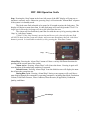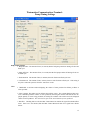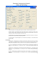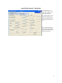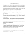
1
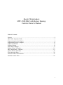
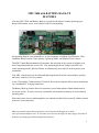
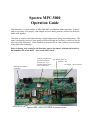
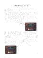
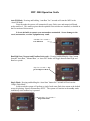
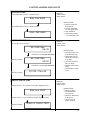
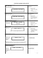
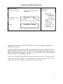
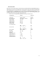
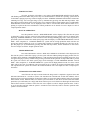
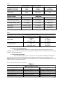
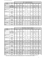
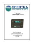
MPC-5000 Owner’s Manual -Mk2 and Farallon Systems - WITH BATTERY BACK-UP Spectra Watermakers, Inc. 20 Mariposa Road, San Rafael, CA 94901 Phone 415-526-2780 Fax 415-526-2787 E-mail: [email protected] www.spectrawatermakers.com Rev. 03-02-2011 2 Spectra Watermakers MPC-5000 MK2 with Battery Backup Controls Owner’s Manual Table of Contents: Features …...…............……...………...........................................................................................4 MPC-5000 Operation Guide …...…............……...………..........................................................5 Programming from the Display …...…............……...………......................................................9 Programming from a Computer.……………………………………………......…...………….12 Software Installation …………………………………………………….......……………........13 Software Settings ……………………………….……………………..…………………….....14 Allow Basic Changes……………………………………………………………………….......17 Salinity Probe Calibration...................................................................................................... .....18 MPC Output States - Detailed.....................................................................................................19 System Alarms and Faults...........................................................................................................23 Power Interrupt States.................................................................................................................26 Auto Store with a Failed Sensor..................................................................................................27 Detailed Controls Data................................................................................................................28 3 MPC 5000 with BATTERY BACK-UP FEATURES Your new MPC 5000 with Battery Back-up is packed with features to make operating your Spectra Watermaker easier, more intuitive and less intimidating. All operating data for your watermaker is at your fingertips, including: Feed Pressure, Filter Condition, Boost Pressure, Water Quality, Operating Mode, and Elapsed Time Counter. The MPC Control Board automatically monitors the operation of the system in real-time to ensure a long and trouble-free service life. If an operating parameter changes, the MPC can switch operating modes, shut itself down, or automatically store itself in order to protect your watermaker. Your MPC control board can be calibrated and programmed from the remote display, quickly and easily with only a few key strokes. A new ‘Watermaker Communication Terminal’ has been developed to allow remote monitoring via a shipboard PC or laptop connection. The Battery Back-up feature allows for temporary power interruptions without detrimental effect on the system. In some cases your watermaker will continue to function in its last known operating state. Please take some time to read through this user manual and familiarize yourself with the control system for your watermaker. Many operational and technical questions can be answered through our website, www.spectrawatermakers.com, we welcome you to browse through our many pages of technical bulletins, operating tips and knowledge based articles. 4 Spectra MPC-5000 Operation Guide This document is a basic outline of MPC-5000 Mk2 and Farallon Mode operations. It details what is seen on the LCD display, what outputs are active during run-time, and how the different modes work together. This mode is used on watermakers having a single high pressure pump, and a boost pump. This mode is defined by having a boost pump feed water through the prefilter(s), which are on the inlet side of the feed pump. Filter condition is measured by an inlet, or boost, pressure sensor on the inlet to the feed pump. Prior to starting your system for the first time, remove the battery isolation tab located to the immediate left of the BATT + post on the MPC board. Ventura, Catalina, Newport Series Systems: Software Ver. A-36 Farallon Systems: Software Version B-14 JP2 Jumper (mk2- on) (Farallon - off) JP1 Jumper - on (all systems) USB Type B Computer Connection Battery Back-up Spectra MPC-5000 CONTROLS printed circuit 5 MPC 5000 Operation Guide Auto Run: Pressing the ‘Auto Run’ button in the top left corner of the remote display will activate the MPC’s Automated Run Sequence. The fresh water flush solenoid valve opens for 20 seconds to prime the feed pump. The display will begin to count down from 10, then feed pump will run in high mode.**Note** In single speed systems the feed pump will run at full speed from the start. The system will now operate in ‘Auto Mode’ for 1 hour. At the end of the run cycle, the system will perform a fresh water flush cycle. At the end of the fresh water flush cycle, the MPC will start the Flush Interval Timer (factory default Flush Timer Interval is set to 120 hours). At the end of the Flush Timer Interval count down the watermaker will perform another fresh water flush followed by the start of the Flush Interval Timer. This process will repeat itself until the user interrupts this process. Auto Run Auto Store: Pressing the ‘Auto Store’ button in the top right corner of the display will activate the ‘Automated Storage Sequence’ in the MPC. This mode will automatically store the system, performing a fresh water flush once every 1 - 10 days, depending on the Flush Timer Interval settings in the MPC. The fresh water flush solenoid will open, and the feed pump will start at flush speed. **Note** Some systems have multiple run speeds, other systems will cycle the pump on and off, and still others will run at full speed. Consult the default settings for the system purchased for details. At the end of the fresh water flush cycle, the MPC will start the Flush Interval Timer (factory default Flush Timer Interval is set to 120 hours). At the end of the Flush Timer Interval count down the watermaker will perform another fresh water flush followed by the start of the Flush Interval Timer. This process will repeat itself until the user interrupts this process. Auto Store 6 MPC 5000 Operation Guide Stop: Pressing the ‘Stop’ button in the lower left corner of the MPC display will stop any action that is currently active. Otherwise, pressing ‘Stop’ will activate the ‘Manual Run’ sequence if the system is in standby mode. The fresh water flush solenoid valve opens for 20 seconds to prime the feed pump. The display will begin to count down from 10, then feed pump will run in high mode.**Note** In single speed systems the feed pump will run at full speed from the start. The system will run indefinitely until the user ends the run cycle by pressing either the ‘Stop’ or ‘Auto Store’ buttons. **Note** If the ‘Stop’ button is pressed to end the run cycle, then a fresh water flush will NOT be done and the system will remain, with raw water throughout, until the ‘Auto Store’ button is pressed. It is advisable to end this cycle by pressing the ‘Auto Store’ button. Stop Alarm/Disp: Pressing the ‘Alarm/Disp’ button will have a variety of different functions depending on the current state of the system. Alarm Active: Pressing ‘Alarm/Displ’ will silence the alarm. Pressing it again will reset the alarm if the underlying condition is corrected. Default Screen: Pressing ‘Alarm/Displ’ from the default screen will display the number of hours the system has run. During Run Cycle: Pressing ‘Alarm/Displ’ during a run sequence will scroll the remote display through the watermaker’s operating parameters; including Run Mode, Production Volume, Feed Water Pressure, Filter Condition, Boost Pressure (If applicable), Production Quality, and Hours. Alarm/Displ 7 MPC 5000 Operation Guide Auto Fill Mode: Pressing and holding ‘Auto Run’ for 5 seconds will start the MPC in the ‘Auto Fill Mode’. From the mode the system will automatically start, flush, store and re-start itself based on the tank level. This mode requires that the optional float switches are installed, as detailed in the first section of this manual. It is not advisable to operate your watermaker unattended. Severe damage to the vessel, watermaker, or other equipment may result. ‘Auto Run’ for 5 seconds => Auto Fill Mode Run High/Low (Newport and Farallon Series only): Pressing and holding the ‘Stop’ button from the ‘Auto Run’, ‘Manual Run’, or ‘Auto Fill’ modes will toggle between Run High and Run Low speeds. ‘Stop’ for 5 seconds => Toggles b/t High/Low Mode Single Flush: Pressing and holding the ‘Auto Store’ button for 5 seconds will activate the ‘Single Flush Mode’. In this mode the system will perform a single fresh water flush, then return to the default screen, displaying “Spectra Watermakers X-XX”. The system will remain in the stand-by mode indefinitely until another key is pressed. ‘Auto Store’ for 5 seconds => Single Flush Mode 8 Programming from the Display The MPC-5000 controls can be programmed directly from the display as well as from a computer. To enter Program Mode the System must be in “Standby Mode”. If the system has been de-powered recently you may need to by-pass the Purge Sequence in order to access the Programming mode. To enter “Standby Mode” Press the “Stop” button from any other mode. The display will read SPECTRA WATERMAKERS B-xx. If it is desired to have the machine running during the programming process, start the machine using the ‘Run Manual’ toggle switch on the Control Box. The machine will run but the controls will go into Standby Mode. To Enter “Program Mode” push and hold the “Stop” and “Alarm/Display” buttons at the exact same time. Hold them down for 4 seconds. If the control does not display “System Units” try again until the display reads “System Units” After entering “Program Mode” the buttons on the Display will have different secondary functions as Follows: Alarm Display: Scroll through the various programming windows by pressing “Alarm Disp” Stop: Selects the digit in the roto flow meter calibration constant window that is to be changed. Has no function in other windows. Auto Run: Changes the selected parameter down one unit per push. Auto Store: Changes the selected parameter one unit up with each push. To Exit Program Mode: Press and release the “Stop” and “Alarm Disp” buttons simultaneously to exit, or the control will automatically revert from Program Mode to Standby Mode if no buttons are pushed for 30 seconds. The programming windows and their functions: SYSTEM UNITS Select Imperial (gallons, psi) or Metric (liters, bar) by pressing “Auto Run” or “Auto Store” FLOW SENSOR TYPE Select Rotoflow or Stroke Sensor with the “Auto Run” or Auto Store” buttons. All Farallon system will have a rotoflow device instead of a stroke senor. PRESSURE RANGE For watermakers with 0-250 psi pressure sensors select High. For all other systems select Low. On Farallon systems this setting is fixed to LOW and cannot be changed. DISABLE AIR LOCK THIS IS A SAFETY SHUTDOWN. SELECT “NO”. Do not select “Yes” unless the system is shutting down on a “System Stalled” alarm due to afailed Roto flow meter. 9 DISABLE PREFILTER: THIS IS A SAFETY SHUTDOWN. SELECT “NO”. Select “Yes” only if you are getting a FALSE “Service Prefilters” alarm. DISABLE PRESSURE: THIS IS A SAFETY SHUTDOWN. SELECT “NO”. Select “Yes” only if you are getting a FALSE “High Pressure” alarm. DISABLE SALINITY: This function allows you to run the watermaker in the event of a salinity probe, probe cable, or salinity sensing circuit failure. If you get a “Salinity Probe Failed” Alarm or the salinity reading cannot be properly calibrated using the “Salinity Cal” function, select “Yes” to continue making water. WARNING: When ”YES” is selected the diversion valve will be energized whenever the watermaker is running. All product water will be sent to the vessel’s water tank regardless of its quality. Before disabling the Salinity Probe test the product water carefully. PPM THRESHOLD: Set this parameter to the desired product water reject salinity. The diversion valve will send water to the water tank when the product parts per million is lower than this set point and reject the product overboard when the salinity is higher than the set point. Factory default setting is 750ppm LOW VACUUM LIMIT (Mk2): Set point for the Maximum allowable pressure drop through the prefilters. If the Inlet Pressure reading drops below this setpoint the unit will alarm “Service Prefilter” and slow down to Run Low Speed. If the pressure drops below this setpoint in Run Low Mode it will alarm Service Prefilters again and shut down. This setpoint is in absolute pressure. This setpoint is also the “Replace” end of the Prefilter Condition bar graph. In most cases this parameter should be set to “10”. MIN. SUPPLY PRESSURE (Farallon): This parameter sets the minimum boost pressure required for the system to operate properly. This is set at the factory, but should be tested after installation. The proper minimum boost pressure setting is set in the same fashion as in Mk2 mode. Set the Minimum Supply Pressure to the nearest whole number higher than the point that the pump began to cavitate. This is read as gauge pressure, and is typically set to 7psi. PRESSURE LIMIT: If the pressure at the feed pump discharge exceeds this set point the unit will shut down and alarm “High Pressure.” The left hand number on the display is the real time feed pressure. The number on the right is the High Pressure limit. Factory default set point varies by model. See the “Computer Settings” for the correct settings for your unit. FLOW CONSTANT: The flow constant calibrates the product flow reading. The number on the left is the real time flow reading and the number on the right is the flow constant. The flow constant is set by selecting the desired digit to be changed by pushing the “Stop Button” until the digit to be changed is flashing. Push “Auto Run” to decrease the value or “Auto Store to increase the value. Then select the next digit to be changed with the “Stop” button. The flow constant is most easily adjusted with the watermaker running on the “Run Manual” switch. Measure the product flow using a graduated container and a stop watch. Adjust the flow constant until the flow reading matches the measured flow. The flow reading is heavily damped and will take some time to stabilize after changes are made to the constant. On Mk2 systems use 25,000 as a starting point for rotor flow meters and 8,300 for Farallon Systems. 10 SALINITY CAL: This window is used to calibrate the salinity sensor. The number on the left is the real time salinity reading and the number on the right is the calibration setting. Increase the setting to raise the reading. See the Salinity Probe Calibration Instructions for details. INLET OFFSET: This parameter calibrates the Boost Pressure sensor found on the intake manifold. The number on the left is the real time pressure reading and the number on the right is the Offset. The reading can be increased or decreased by putting a positive or negative number in the Offset setting. OUTLET OFFSET: Outlet Offset calibrates the sensor on the outlet of the feed pump which is used to determine feed pressure or membrane pressure and to protect the system from overpressurization. The number on the left is the real time pressure reading and the number on the right is the Offset in psi or bar. BRIGHTNESS: Four brightness levels can be selected if the unit is equipped with an adjustable Vacuum Fluorescent Display. Change the parameter with the Auto Store button to select the desired level. FLUSH DURATION: This parameter sets the length of the fresh water flush in minutes. It should be set to equal the sum of twice the pump off time plus the pump on time. PUMP ON TIME: Sets the length of time the feed pump will run during the flush. Set this parameter to the time in seconds that it takes for fresh water to begin to come out of the brine discharge during the flush. PUMP OFF TIME: Sets the time in seconds that the flush valve is open, but the feed pump is not running, at the beginning and end of the flush cycle. During the pump off time flush water flows backwards through the prefilters and sea strainer, filling them with fresh water and removing some of the material they trapped. FLUSH INTERVAL: This is the time in hours between automatic flushes when the system is in “Auto Store” mode. Factory default is five days (120 hours). CLEAN PRESSURE: This should be set to the pressure seen at the Inlet Sensor when the system is running with brand new filters. After installing new filters, run the machine using the ’Auto Run’ button and note the boost pressure in the top right corner of the Filter Condition menu. Set the right hand number in theClean Pressure screen in the Programming Mode to match the real time pressure noted above. This parameter sets the “Clean” end if the prefilter condition bar graph. 11 Programming from a Computer (Mk2 Systems Only) The MPC-5000 with Battery Backup can be programmed from a Windows based computer. Spectra version 2.2 Watermaker Communication Terminal must be installed on the computer and the computer connected to the MPC-5000 printed circuit board with a USB cable with a Type B connection at the opposing end. The Spectra Watermaker Communication Terminal ‘Status’ window 12 Software Installation from CD: 1) Insert the Spectra Watermakers CD-ROM into the computer’s CD-ROM drive. 2) Using “My Computer” or Windows Explorer, locate and double-click the “dotnetfx.exe” file on the CD-ROM drive. This will install the necessary framework for the communication terminal. Follow the on-screen instructions. 3) When the framework is installed, locate and double click the file “setup.exe” from the same folder as the dotnetfx file. Follow the on screen instructions. 4) Connect a USB cable from an open USB 2.0 port to the USB port on the MPC 5000 controller, and open the program. 5) If the “Found New Hardware” message pops up, go to step 6. If the message in the upper right corner of the Communication terminal says “Communicating” then continue on to the next page. 6) Select the prompt that allow you to install the driver from a specific location. 7) Browse the CD drive containing the installation disk and select ‘Drivers’. Click ‘Open’ 8) Restart your computer 9) Reconnect the USB cable to the MPC board, and open the Watermaker Communication Terminal. The message in the upper right corner of the screen should scroll from ‘Disconnected’, to ‘Searching’ and after several seconds, ‘Communicating’. Setup.exe Dotnetfx.exe file Message Window 13 Watermaker Communications Terminal Pressure Control Settings Pressure Control Settings 1. Membrane Pressure Limit: This is the upper allowable pressure limit from the feed pump. The max pressure is factory set to the highest recommended operating pressure to avoid damaging the membrane and/or pump components. 2. Minimum Supply Pressure: The minimum allowable boost pressure as measured by the Boost Pressure Sensor. This setting should be calibrated at time of installation to the lowest operating pressure reading BEFORE the feed pump begins to cavitate. 3. Low Vacuum Limit/Minimum Supply Pressure: The real-time reading of the boost pressure at the inlet to the pump. 4. Inlet Offset: The setting used to calibrate the Boost Pressure Sensor 5. Feed Pressure/Membrane Pressure: The real-time reading of the outlet pressure from the pump. In Catalina and Newport series systems, this will be the feed water pressure from the vane pump to the Clark Pump. In Farallon Series systems this will be the membrane pressure. 6. Outlet Offset: The setting used to calibrate the Feed Pressure or Membrane Pressure Sensor. 7. Clean Filter Pressure: The calibration setting for determining the highest available boost pressure with brand new filters installed. Must be calibrated at time of installation. 8. 250psi Transducers: Check this box if the system uses 250psi pressure transducers. If the system 14 uses 150psi transducers, leave this box unchecked. Does not apply to Farallon Systems. Watermaker Communications Terminal Pump Timing Settings Pump Timing Settings 1. Pump On Time: The amount of time, in seconds, that the feed pump remains on during a fresh water flush cycle. 2. Pump Off Time: The amount of time, in seconds, that the feed pump remains off during a fresh water flush cycle. 3. Flush Duration: The amount of time, in minutes, that each fresh water flush cycle lasts. 4. Flush Interval: The amount of time, in hours, between each fresh water flush cycle. This setting is only active when the system is left in the ‘Auto Store’ mode. Flow 1. GPM/LPM: A real-time readout displaying the volume of water produced in Gallons per Hour or Liters per Hour. 2. Flow Constant: The setting used to calibrate the rotoflow sensor. The constant displayed has an inverse relationship with the volume of water produced; increasing the constant will decrease the displayed quantity of water being produced, decreasing the constant value with increase the displayed volume of water produced. This value has no effect on the actual amount of water produced. 3. Rotoflow: Checking this box tells the MPC Control Board to monitor the signal from the Rotoflow meter. If the box is not checked, then the MPC Control Board will look for a signal from a Stroke Sensor. 15 Watermaker Communications Terminal Salinity and Fault Settings Salinity Settings 1. PPM: The quality of water being produced by the watermaker. Measured in parts per million. 2. Salinity Constant: The calibration setting for the salinity readout. Increasing the constant will increase the salinity reading, decreasing the constant will decrease the salinity reading. Altering this setting has no effect on the actual quality of the product water. 3. PPM Threshold: The setting that determines the minimum acceptable water quality to be diverted to the tank. This is set by the factory at 750 parts per million. 4. Display Brightness: Adjust the brightness of a Vacuum Fluorescent Display. 0 is the default and the brightest setting. Fault Disables 1. Salinity Probe: Checking this box will disable the alarm fault ‘Salinity Probe Failed’ on the MPC remote display. Be enabling this feature, the diversion valve will always be engaged, regardless of the quality of the water produced. Always be certain to test the water quality prior to filling your tanks. 2. Air Lock: Checking this box will disable the ‘System Stalled’ alarm. Be absolutely certain that you are receiving a false alarm prior to disabling this feature or serious and irreparable damage will occur. 3. High Pressure: Checking this box will disable the alarm fault ‘High Pressure’. Be absolutely certain that you are receiving a false alarm prior to disabling this feature or serious and irreparable damage will occur. 4. Prefilter: Checking this box will disable the alarm fault ‘Service Prefilters’. Be absolutely certain that you are receiving a false alarm prior to disabling this feature or serious and irreparable damage will occur. 16 ALLOWING BASIC CHANGES On the Menu Bar, Click ‘Tools’, then ‘Settings’ and Allow Basic Changes This mode will allow you to make basic changes to the Salinity Constant, Flow Constant, and Clean Filter Pressure. Allow Advanced Changes is password protected and can only be accessed by a factory authorized technician. 17 Salinity Probe Calibration: Salinity is a measurement of dissolved solids in liquid: these solids will conduct electricity to varying degrees. A special probe is used, with two electrical contacts in it, to determine the resistance to the flow of electricity in the liquid. The higher the resistance, the lower the PPM of dissolved solids. In the Mk2 and Farallon systems, the salinity probe is located in a port on the bottom of the pump module manifold. This way we can look at the salinity level of the product water before deciding to either reject the water or accept it and divert it into the holding tank. The salinity level in parts-per-million can be seen through the remote display. Using a hand-held tester, note the salinity in parts per million (ppm) of your product water after the unit has been running, be sure to calibrate the hand -held salinity meter as per the manufacturer’s instructions. The salinity circuit can be adjusted from the display in the Salinity Cal window, or from the Watermaker Communication Terminal by adjusting the “Salinity Calibration” parameter. Increase the calibration parameter to increase the salinity reading. From the Display: Access the ‘Program Mode’ from the remote display (simultaneously press and hold the ‘Stop’ and ‘Alarm/Displ’ buttons for 4 seconds). Press ‘Alarm/Displ’ to scroll through the menus until you reach the ‘Salinity Cal’ heading. This window is used to calibrate the salinity sensor. The number the left is the real time salinity reading and the number on the right is the calibration setting. Increase or decrease the setting until the number on the left corresponds to the number acquired from the handheld tester. From a PC: Connect your PC to the MPC board (see detailed instructions earlier in this manual). Open the ’Watermaker Communication Terminal’ program. Select the ‘Settings’ tab from the Watermaker Communication Terminal. In the ‘Tools’ menu at the top of the program, select ‘Settings’ then ‘Allow Basic Changes’. Adjust the ‘Salinity Constant’ below the salinity readout, until the desired reading in parts per million (ppm) is reached. Note: Occasionally it may become necessary to calibrate the handheld salinity tester. In order to properly calibrate this probe a water sample of known salinity must be acquired. These are available from Spectra, p/n EL-SLT-CGS8. 18 Current State Output State Display Message Power On Initial Startup Purge Mode Power On Auto Run OPEN PRESSURE RELIEF VALVE NOW STARTING 00:30 All Off, Aux1 On Pump2, Fvlv, Pvlv, Aux1, Aux2, Aux3 or Stop Purging PURGING STORAGE SOLUTION 18:30 Pump2, Aux1, Aux2 Aux3 Countdown to 0:00 Done CLOSE PRESSURE RELIEF VALVE NOW All Off, Aux1 On Close pressure relief valve and press Auto Run Auto Run RUN AUTO MODE 1:00 Pump2, Pvlv, Aux1, Aux2, Aux3Ster Displayed for 10 secs Priming Making Water Bypass Purge Mode PURGING PRODUCT 10:00 RUN AUTO MODE 00:59 HOURS Pump1, Pump2, Aux1, Aux2, Aux3, Ster Pump1, Dvlv*, Aux1, Aux2, Aux3, Ster Auto Run and PURGE MODE BYPASSED Stop Simultaneously 19 Current State Output State Display Message RUN HIGH MODE Stop Manual Run Mode Pump2, Fvlv, Pvlv, Aux1, Aux2, Aux3, Ster Displayed for 20 secs Priming Making Water STARTING 00:09 GPH PRODUCT 17.2 Pump2, Fvlv, Pvlv, Aux1, Aux2, Aux3, Ster Pump1, Dvlv*, Aux1, Aux2, Aux3, Ster *NOTE: If salinity is out of tolerance, the diversion valve will close, and the “reject” LED will be lit. Salinity must drop below tolerance diversion valve will open. Press RUN HIGH MODE Low Mode Pump2, Fvlv, Pvlv, Aux1, Aux2, Aux3, Ster Start Stop Then press again Start Stop RUN LOW MODE Pump2, Fvlv, Pvlv, Aux1, Aux2, Aux3, Ster ...and hold for 5 seconds Displayed for 20 secs STARTING When 30 seconds remaining, Pump2 Off, Pump1 On 00:09 GPH PRODUCT 08.5 Pump1, Dvlv*, Aux1, Aux2, Aux3Ster 20 Current State Output State Display Message Auto Run Mode Auto Run RUN AUTO MODE 01:00 HOURS Pump2, Fvlv, Pvlv, Aux1, Aux2, Aux3, Ster Note: pressing “Auto Run” again will add time in 1 hour increments Priming 30 seconds Making Water STARTING 00:09 RUN AUTO MODE 0:59 HOURS Pump2, Fvlv, Pvlv, Aux1, Aux2, Aux3, Ster Pump1, Dvlv*, Aux1, Aux2, Aux3, Ster Countdown to 0 Flush FRESH WATER FLUSH 5:00 Fvlv, Aux1, Aux2 Pump2, Fvlv, Pvlv, Aux1, Countdown to 0 Storage FLUSH TIMER INTERVAL 119:59 Aux1 Countdown to 0 Perform Flush Cycle Repeats Note: Pump2 flush on/off times (seconds), as well as storage time (hours), are programmable via internal software Auto Auto Store Store Modee Mode Auto Store STARTING Pump2, Fvlv, Pvlv, Aux1 5:30 Flush Storage FRESH WATER FLUSH 5:00 FLUSH TIMER INTERVAL 119:59 Pump2 Fvlv, Aux1, Aux2 Aux1 Countdown to 0, repeat flush. Cycle repeats. 21 Current State Output State Display Message Press and hold AUTO FILL MODE Auto Fill Mode Auto Run Pump2, Pvlv, Aux1, Aux2, Aux3Ster For 5 seconds STARTING 1:30 When 30 seconds remaining, Pump2 Off, Pump1 On AUTO FILL MODE Pump1, Pump2, Dvlv*, Aux1, Aux2, Aux3Ster Will produce water until tank 1 switch closes Auto Fill Mode Tank/s Full If Tank1 (max) Switch closes.. TANK/S FULL Pump2, Fvlv, Pvlv, Aux1 STARTING 5:30 TANK/S FULL FRESH WATER FLUSH 5:00 Pump2 Fvlv, Aux1, Aux2 Display will toggle “Tank/s Full” to “Fresh Water Flush” every 5 seconds Countdown to 0 TANK/S FULL FLUSH TIMER INTERVAL 119:59 Aux1 Display will toggle “Tank/s Full” to “Flush Timer Interval” every 5 seconds Countdown to 0 If timer reaches zero, another fresh water flush will be performed If tank 2 (min) switch opens, the timer will interrupt, and the unit will go back into auto-fill mode (production mode) 22 SYSTEM ALARMS AND FAULTS HIGH PRESSURE If Feed/Membrane Pressure > Pressure Limit Shutdown, Audible Alarm Alarm LED lit RUN LOW MODE If Feed/Membrane Pressure > Pressure Limit HIGH PRESSURE RESOLUTION: Check for kinked or blocked hoses Confirm ‘Outlet Offset’ in Program Mode Clean Membrane Clark Pump problems - see tech bulletin CP5 SYSTEM STALLED Shutdown, Audible Alarm Alarm LED lit If no product for 30 seconds: RE-STARTING 00:30 Countdown to 0, retry previous mode RE-STARTING 00:30 If still no product Countdown to 0, retry previous mode RESOLUTION: Confirm product water at membrane endcap Check intake line for restrictions, blockages or air leaks Close Pressure Relief Valve on Pump Check Rotoflow Meter wiring Confirm MPC settings correct SYSTEM STALLED If still no product SERVICE PREFILTERS Shutdown, Audible Alarm Alarm LED lit If Inlet Pressure < Low Vacuum Limit (Min. Supply Pressure) RUN LOW MODE If Inlet Pressure < Low Vacuum Limit (Min. Supply Pressure) RESOLUTION: Change prefilters Confirm adequate boost pressure Check for obstructions in intake line Check sensor for proper operation SERVICE PREFILTERS If still no product 23 SYSTEM ALARMS AND FAULTS Begin FWF Mode To Shutdown LOW VOLTAGE If DC Input voltage too low: VOLTAGE TOO LOW RESOLUTION: Check wiring to MPC board Check battery state HIGH VOLTAGE Begin FWF Mode To Shutdown If DC input voltage too high: VOLTAGE TOO HIGH RESOLUTION: Check battery charger Replace EEPROM chip Shutdown SALINITY PROBE FAILED If salinity probe bad or disconnected: SALINITY PROBE FAILED RESOLUTION: Check probe connections Replace probe Shutdown CHECK FUSE If blown fuse CHECK FUSE X (Where ‘x’ represents number of blown fuse (1-5)) RESOLUTION: Check equipment connected to corresponding output Replace fuse TANK/S FULL If Tank1 AND Tank2 switch closed for 2 minutes: TANK/S FULL See Detailed Output State Chart on pg 33 Depending on operating mode, system may at this point begin a fresh water flush, begin storage mode, or shut down. Refer to “Operating Modes”. POWER INTERRUPT POWER INTERRUPT If power is interrupted to the MPC board for up to 10 days See Detailed Output State Chart on pg 13 24 SYSTEM ALARMS AND FAULTS HIGH SALINITY If salinity above tolerance: If salinity above tolerance for 20 minutes:: Reject lamp lit, 20 minute internal counter begins SALINITY HIGH FLUSH 5:00 SALINITY HIGH Shutdown Begin FWF Mode Audible Alarm Alarm LED lit RESOLUTION: Check pump operation Clark Pump Feed Pump Pearson Pump Confirm product water quality Membrane damage clean or replace Salinity probe out of calibration Clean or replace probe The battery back-up feature on the MPC 5000 has some special operating circumstances, detailed on the next page. If the power supply to the MPC Control Board is disrupted for any reason, the MPC Control Board will retain its last known state. Once power is restored to the board, internal logic in the MPC will determine the best action. The matrix on pg 13 will detail what the Remote Display will read and how the Control Board will react. **Note: One some MPC 5000 systems with Battery Back-up there will be a 10 delay while the system reboots after restoring power. During this delay the Remote Display may show an Alphanumeric code. This is normal, and the board will reset itself shortly. 25 MPC 5000 with Battery Back-up Software Revisions A-36/B-14 Power Interruption States Current state Power off <10 min Off Power off 10 min-5 days Off Off Purge Solution: "Open Pressure Re- Purge solution: "Open pressure Purge solution: "Open pressure relief valve now." relief valve now." lief Valve Now" Purge Solution: "Purging Storage Solution" Purge solution: "Open pressure Purge solution: "Open pressure relief valve now." relief valve now." Purge Product: "Close Pressure Re- Purge solution: "Close pressure Purge solution: "Open pressure relief valve now." relief valve now." lief Valve Now" Purge Product: "Purging Product" Purge solution: "Close pressure Purge solution: "Open pressure relief valve now." relief valve now." Manual Run: High/Low Speed Alarm: "Power Interrupt" Return to Stand-by Mode Alarm: "Power Interrupt" Return to Stand-by Mode Auto Run: High/Low Speed Alarm: "Power Interrupt" Return to Stand-by Mode Alarm: "Power Interrupt" Return to Stand-by Mode Auto Flush: Running flush Alarm: "Power Interrupt" Return to Stand-by Mode Alarm: "Power Interrupt" Return to Stand-by Mode Auto Flush: "Flush Interval Timer" Continue Flush Interval Timer Minus Time Elapsed Continue Flush Interval Timer Minus Time Elapsed Auto Flush Timer Expires While Power Is Off Alarm: "Power Interrupt" Return to Stand-by Mode Alarm: "Power Interrupt" Return to Stand-by Mode Single Flush Alarm: "Power Interrupt" Return to Stand-by Mode Alarm: "Power Interrupt" Return to Stand-by Mode Auto Fill: Tank Switches Closed Continue Flush Interval Timer Continue Flush Interval Timer "Tank/s Full" - Waiting for Low Tanks Minus Time Elapsed; Remain in Minus Time Elapsed; Remain in Auto Fill Mode Auto Fill Mode Auto Fill: Tank Switches Open - Mak- Return to Auto Fill Making Wa- Return to Auto Fill Making Water ter ing Water Auto Fill: Tanks Full, Flushing System. Restart Flush Restart Flush ** After 5 days, all power up states are Purge Solution : "Open pressure relief valve now." 26 Performing a Fresh Water Flush with a Failed Salinity Probe In the event of a ‘Salinity Probe Failed’ alarm on the remote display the alarm function can be defeated to allow the system to remain in the Auto Store mode until repairs can be facilitated. Access the Program Mode, as outline in this manual in the section titled “Programming from the Display”. Scroll through t he menus until you reach the ‘Disable Salinity’ heading. Press the ‘Auto Store’ button once, this will change the setting from ‘NO’ to ‘YES’. Wait 40 seconds for the display to timeout and return to the default screen. Press ‘Auto Store’ once. The system will begin Auto Store Mode, as outlined earlier in this manual. Performing a Fresh Water Flush with a Failed Inlet Pressure Transducer In the event of a ‘Service Prefilter’ alarm on the remote displaythat cannot be cleared by replacing the pre-filter(s) for new, the alarm function can be defeated to allow the system to remain in the ‘Auto Store’ mode until repairs can be facilitated. Access the Program Mode, as outlined in this manual in the section titled “Programming from the Display”. Scroll through t he menus until you reach the ‘Disable Salinity’ heading. Press the ‘Auto Store’ button once, this will change the setting from ‘NO’ to ‘YES’. Wait 40 seconds for the display to timeout and return to the default screen. Press ‘Auto Store’ once. The system will begin Auto Store Mode, as outlined earlier in this manual. 27 Detailed MPC Controls Data CONTENTS HARDWARE DESCRIPTION…… …………………………………………………….……………..28 INPUTS……………………………………………… ………………………….……………..28 OUTPUTS…………………………………………… ………………………….……………..28 BASIC FUNCTIONS………...……………………………… … ……………………….……………..28 DISPLAY OPERATION…………..……………… ………………………….……………..28 PROGRAM MODE……………………………………..……………………….……………..29 PURGE FUNCTION……………….………………..………… ………….……………..…..30 MANUAL OPERATION..…………………………..……………………….……………..…..30 TIMED OPERATION..…….………………………..……………………….……………..…..30 AUTOMATIC FILL OPERATION..…………….…..……...……………….……………..…..30 MANUAL FLUSH OPERATION..………………………………………….……………..…..31 TIMED FLUSH OPERATION……………………………………………….……………..….31 FAULT HANDLING PROTOCOL…………………………………………………… ….……………32 ELECTRICAL SPECIFICATIONS..…………………………………………………….… .…………..34 28 I. HARDWARE DESCRIPTION: INPUTS: FLOW METER – Rotor Flow meter used to determine water flow rate and detect possible air in the system. Connect to Stroke sensor terminals. SEA STRAINER – normally open switch used to monitor Sea Strainer state. FLOAT SWITCHES - normally open switches used to monitor fresh water tank status, switch 2 is for minimum level, and switch 1 is for maximum level. INLET PRESSURE sensor – absolute pressure transducer used to monitor the boost pressure and the condition of the pre-filters. OUTLET PRESSURE sensor - pressure transducer (150 or 250psi max) used to measure the feed water pressure being delivered to the Clark Pump and membrane. SALINITY PROBE – sensor used to monitor salinity and temperature of product water. OUTPUTS: BUZZ – Piezo buzzer output. PVLV – Priming valve solenoid. FWV – Fresh water valve solenoid. AUX3 – Boost Pump output. PMP1 – Feed Pump ‘Run High’ signal. DVLV – Diversion valve solenoid. PMP2 - Feed Pump ‘Run Low/Flush Speed’ signal. AUX1, AUX2 – Auxiliary outputs. STER – Optional UV sterilizer. II. BASIC FUNCTIONS: DISPLAY OPERATION: BUTTON FUNCTIONS: STOP – pressing this button will toggle unit between ON and OFF states, pressing and holding this button for 3 seconds will toggle system between High and Low Production rates. AUTO RUN – pressing this button will activate Timed Production mode, pressing and holding this button for 3 seconds will activate Auto Fill mode. STOP & AUTO RUN pressed simultaneously will bypass Purge cycle. AUTO STORE – pressing this button will activate Timed Flush mode, pressing and holding this button for 3 seconds will activate Single Flush. ALARM DISPL - pressing this button will allow user to view system operating parameters, silence buzzer and turn off alarm led. AUTO STORE & ALARM DISPL pressed and held simultaneously for 3 seconds will activate Program mode. LED FUNCTIONS: STOP – continuously lit while system is in Manual production mode. AUTO RUN - continuously lit while system is in Timed production mode, blinks while system is in Auto Fill mode. AUTO STORE - continuously lit while system is in Manual Flush mode, blinks while system is in Timed Flush mode. ALARM DISPL – blinks to warn the user about an action to be taken or fault condition. REJECT – lit when salinity exceeds programmed threshold. GOOD - lit when salinity is below programmed threshold. 29 PROGRAM MODE: This mode is used for system setup. To enter this mode press and hold STOP & ALARM DISPL buttons simultaneously for 4 seconds. AUTO RUN button is used to decrement value of the parameter or blinking digit. AUTO STORE button is used to increment value of the parameter or blinking digit. STOP button moves cursor right one character. ALARM/DISPL button is used to advance to the next programmable parameter. Unit will automatically exit from Program mode if no buttons are pressed for 40 seconds. All changes made to programmable parameters will be saved upon exiting program mode. Below is a list of all programmable parameters, their ranges and default values: PARAMETER RANGE DEFAULT ------------------------------------------------------------------------------------------------System units Imperial / Metric Imperial Flow Sensor Type Stroke Sensor / Rotoflow Rotoflow Pressure Range Low / High Low Disable Airlock No / Yes No Disable Prefilter No / Yes No Disable Pressure No / Yes No Disable Salinity No / Yes No PPM Threshold 0 – 1020 748 Low Vacuum Limit PSI 7 – 20 10 BAR 0.48 – 1.37 0.68 Pressure Limit PSI 50 – 250 150 BAR 3.44 – 10.34 10.34 Flow Constant 2000 - 16000000 25000 Inlet offset -99 – +99 0 Outlet offset -99 – +99 0 Brightness 0–3 0 Flush duration, min 1 – 15 5 Pump ON time, sec 1 – 420 3 Pump OFF time, sec 0 – 420 0 Flush interval, hrs 10 – 240 120 Clean Filter Pressure PSI 12 – 30 15 BAR 0.82 – 2.06 1.03 30 PURGE FUNCTION: On power up display will indicate a user prompt “OPEN PRESSURE RELIEF VALVE NOW” with flashing Alarm LED. When user presses Stop or Auto Run button to confirm valve opening, system will run for 20 minutes purging any storage solution. Display will show “PURGING STORAGE SOLUTION” and the time remaining for Purge. User can bypass Purge cycle by simultaneously pressing Auto Run and Stop buttons. Auto Store button is ignored while system waits for purge to be completed. When system finishes purge “CLOSE PRESSURE RELIEF VALVE NOW” will be displayed, buzzer will be activated and Alarm LED will flash. No repriming is required at this time and Manual or Timed production can be started. For active outputs see table 4 “Output operation status”. MANUAL OPERATION: Press Stop button to activate. “RUN HIGH MODE” will be displayed. The first time the system is started after a purge cycle the system will start without priming and purge product water for 10 minutes while displaying “PURGING PRODUCT” with count down timer showing remaining purge time. If the Stop button is pressed the system will return to the initial system purge mode and display “CLOSE PRESSURE RELIEF VALVE NOW”. After completion of “PURGING PRODUCT” system will run in high production mode until the user presses Stop again to end the run cycle or, if optional float switches are installed, the tank(s) are full. User can bypass this purge cycle by simultaneously pressing Auto Run and Stop buttons, but this should not be done unless. For active outputs see table 4 “Output operation status”. TIMED OPERATION: Press Auto Run button to activate. “RUN AUTO MODE 01:01 HOURS” will be displayed. The first time the system is started after a purge cycle the system will start without priming and purge product water for 10 minutes while displaying “PURGING PRODUCT” with count down timer showing remaining purge time. User can bypass this purge cycle by simultaneously pressing Auto Run and Stop buttons. If Stop button will be pressed the system will return to the initial system purge mode and display “CLOSE PRESSURE RELIEF VALVE NOW”. After completion of “PURGING PRODUCT” system will run High production mode for 1 hour or until tank/s will be full. Time for production can be increased for up to 12 hours by pressing Auto Run button. At the end of production time system will switch to the Timed Flush mode. For active outputs see table 4 “Output operation status”. AUTOMATIC FILL OPERATION: Auto Fill mode can only be activated when the Purge mode is completed or bypassed. Press and hold Auto Run button for 3 seconds to activate. The Auto Run led will blink and “AUTO FILL MODE” will be displayed. System will start production if both Float switches are open and continue until the tank(s) are full (both Float switches closed). When the tank(s) are full the system will switch to Auto Store mode and will start another production cycle when tank(s) are empty (both Float switches open) or will fresh water flush again when the Flush Interval Timer reaches 0, whichever comes first. For active outputs see table 4 “Output operation status”. Table 1 on pg 32 describes operation when the system is switched to Auto Fill mode; Table 2 describes operation while system is in Auto Fill mode: 31 Table 1. Switched to Auto Fill Table Maximum Level Switch Minimum Level Switch Open Open Open Closed Closed Open/Closed Tank's State Empty Above Min Full Previous State OFF Production Mode New State Timed Flush Timed Flush Timed Production Mode No Change No Change Timed Flush Manual Production Mode No Change No Change Single Flush Timed Flush Production Mode No Change No Change Single Flush Production Mode Timed Flush Timed Flush Table 2. In Auto Fill ModeTable Current State Button Pressed Start/Stop Auto Flush/Auto Flush Start/Stop Auto Flush/Auto Flush Timed Flush Production Mode New State Off No Change No Change Off No Change Timed Flush 7. MANUAL FLUSH OPERATION: Press and hold Auto Store button for 3 seconds to activate. The Auto Store led will be on and “FRESH WATER FLUSH” with count down timer showing remaining flush time will be displayed. For active outputs see table 4 “Output operation status”. 8. AUTO FLUSH OPERATION: Press Auto Store button to activate. The Auto Store led will blink and “FRESH WATER FLUSH” with count down timer showing remaining flush time will be displayed. When flush will be completed “FLUSH TIMER INTERVAL XXX: XX” will be displayed. The next flush will occur at the end of the flush interval. For active outputs see table 4 “Output operation status”. Table 3 below describes allowed mode changes: Table 3. Manual to Auto Fill Manual to Timed Manual to Off Timed to Off Auto Flush to Off Single Flush to Off MODE C HANGES ALLOWED Manual to Auto flush Timed to Single Flush Timed to Auto Fill Auto Flush to Timed Auto Flush to Auto Fill Single Flush to Timed Manual to single Flush Timed to Auto Flush Auto Flush to Single Flush Single Flush to Auto Flush Single Flush to Auto fill Off to Any Mode 32 Table 4: Output operation status. function Purging Solution Purging Product Auto Run (1) time 0-30sec 30sec-20min after 20min Buzzer PVLV on on FWV (4) Mk I – Jumper JP2 removed Aux3 Pump1 DVLV Pump2 Aux1 on on on on on on on on on on on on on on on on on on on on on on on on on on on on on on on on on on 0-30sec 30sec-n hours on 0-30sec after 30sec on 0-30sec >30sec on Auto Flush 0-5min (3) (4) (3) on (3) Flush 0-5min (3) (4) (3) on (3) Auto Fill Manual run high function Purging Solution Purging Product Auto Run (1) time 0-30sec 30sec-20min after 20min (4) on Buzzer PVLV on on (4) (4) FWV (4) on on on on on on on on (2) (2) (2) Mk II System– Jumper JP2 installed Aux3 Pump1 DVLV Pump2 Aux1 on on on on on on on on on on on on on on on on on on on on on on on on on on on on on on on on on on on on on on on on on on 0-30sec after 30sec on 0-30sec >30sec on 0-30sec >30sec on Auto Flush 0-5min (3) (4) (3) on (3) Flush 0-5min (3) (4) (3) on (3) 33 Manual run high Manual run low (1) (4) (4) (4) on Ster 0-30sec 30sec-n hours Auto Fill (4) on Aux2 on on on 0-10min Ster on on 0-10min Aux2 on on (2) on on on (2) on on on (2) on on (2) After running 1-12 hours system runs an auto flush function (2) DVLV turns on for 2.5 sec then switches to PWM output at 17% duty cycle (3) on/off timing controlled by pump on/off programming (4) on if 12v else 50% duty cycle if 24V system 33 III FAULT HANDLING PROTOCOL. When any fault occurs display will indicate an appropriate message, Alarm led and buzzer will be turned on. Pressing ALARM DISPL button will silence buzzer, pressing the button second time will clear fault message from display if fault had been cleared. High Salinity – The system will terminate production if salinity remains above programmed threshold for 20 minutes. Display will indicate “SALINITY HIGH” and system will switch to flush. Salinity Probe Failed - The system will terminateproduction. Display will indicate “SALINITY PROBE FAILED” and system will switch to flush. Fuse failure - The system will terminate operation. Display will indicate “CHECK FUSE XX”. System Stalled – If no pulses will be detected for 30 seconds during any production mode the system will stop and restart. If this condition occurs 3 times during one production cycle, the system will terminate operation and display will indicate “SYSTEM STALLED”. Tank/s full – If float switch 1 (maximum level) will be closed for 2 minutes the system will terminate production and will switch to flush. Display will indicate “TANK/S FULL” alternating with “FRESH WATER FLUSH”. No alarm will be activated while in Auto Fill mode. High voltage – The system will terminate production if the battery voltage raises above 14.8 VDC (12 V systems) or 29.6 VDC (24 V systems) for 2 minutes. Display will indicate “HIGH VOLTAGE” and system will switch to flush. Low voltage – The system will terminate production if the battery voltage decreases below 11.5 VDC (12 V systems) or 23VDC (24 V systems) for 2 minutes. Display will indicate “LOW VOLTAGE” and system will switch to flush. High feed water pressure (Newport) – If feed water pressure rises above programmed limit, the system will switch to Low production mode for 10 seconds. If feed water pressure will not decrease below programmed limit within 10 seconds, the system will terminate operation and display will indicate “HIGH PRESSURE”. Service Prefilters – If Vacuum decreases below the programmed Low Vacuum limit for 10 seconds, the system will terminate operation and display will indicate “SERVICE PREFILTER”. Power Interrupt - System has experienced an interruption in the power supply. See the matrix on page 13 for a detailed explanation of the MPC’s actions immediately following a power interruption. 34 IV. ELECTRICAL SPECIFICATIONS. Operating voltage limits, VDC: 11.6 – 13.8 for 12 V systems 23.2 – 27.6 for 24 V systems Controller power consumption, mAmp – 700 maximum Outputs: BUZZ – 100 mA DC Piezo buzzer. PVLV – 2.5 Amp DC priming valve solenoid. FWV – 2.5 Amp DC fresh water valve solenoid. AUX3 – 5 Amp DC auxiliary output. PMP1 – 15 Amp DC auxiliary water feed pump. DVLV – 10 Amp DC diversion valve solenoid, modulated at 17% duty cycle after 2.5 seconds to reduce power consumption. PMP2 - 15 Amp DC main water feed pump. AUX1 - 2.5 Amp DC auxiliary output. AUX2 – 2.5 Amp DC auxiliary output. STER – 5 Amp DC sterilizer. 35 36