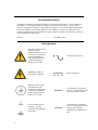
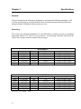
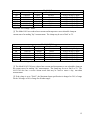
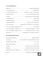
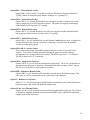
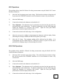
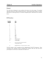
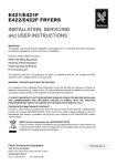
1
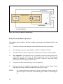
Valhalla Scientific, Inc. 4100 SERIES DIGITAL OHMMETER OPERATION MANUAL 8318 Miramar Mall San Diego, CA 92121 P: 858/457-5576 F: 858/457-0127 W: www.valhallascientific.com VALHALLA SCIENTIFIC INC. CERTIFICATION Valhalla Scientific, Inc. certifies that this instrument was thoroughly tested and inspected and found to meet published specifications when shipped from the factory. Valhalla Scientific, Inc. further certifies that its calibration measurements are traceable to the Nation Institute of Standards and Technology to the extent allowed by NIST’s calibration facility. Due to continuing product refinement and due to possible parts manufacturer changes, Valhalla Scientific, Inc. reserves the rights to change any or all specifications without notice. VALHALLA SCIENTIFIC INC. WARRANTY STATEMENT The warranty period for this instrument is stated on your invoice and packing list. Please refer to these to determine appropriate warranty dates. We will repair the instrument during the warranty period provided it is returned to Valhalla Scientific, Inc. freight prepaid. No other warranty is expressed or implied. Valhalla Scientific, Inc. is not liable for consequential damages. Permission and a Return Material Authorization number (RMA) must be obtained directly from the factory for warranty repairs. No liability will be accepted if returned without such permission. Due to continuing product refinement and due to possible parts manufacturer change, Valhalla Scientific reserves the right to change any or all specifications without notice. 4100 Digital Ohmmeter User Manual Edition 1 Copyright © 1996 Valhalla Scientific, Inc. All rights reserved 2 Documentation History All Editions and Updates of this manual and their creation date are listed below. The first Edition of the manual is 1. The Edition Number increments by 1 whenever the manual is revised. Updates, which are issued between Editions, contain replacement pages to correct or add additional information to the current Edition of the manual. Whenever a new Edition is created, it will contain all of the Update information for the previous Edition. Each new Edition or Update also includes a revised copy of this documentation history page. Edition 1 ………………………………………………….November, 1995 Safety Symbols Instruction manual symbol affixed to product. Indicates that the user must refer to the user manual for specific WARNING or CAUTION information to avoid personal injury or damage to the product Alternating current (AC) WARNING, RISK OF ELECTRICAL SHOCK. Direct current (DC) Indicates the field wiring terminal that must be connected to ground before operation the equipment --protects against electrical shock in case of fault. Frame or chassis ground terminal --- typically connects to the equipment’s metal frame. 3 WARNING Calls attention to a procedure, practice, or condition that could cause bodily injury or death. CAUTION Calls attention to a procedure, practice, or condition that could possibly cause damage to equipment or permanent lost of data. WARNINGS The following general safety precautions must be observed during all phases of operation, service, and repair of this product. Failure to comply with these precautions or with specific warnings elsewhere in this manual violates safety standards of design, manufacture, and intended use of the product. Valhalla Scientific assumes no liability for the customer’s failure to comply with these requirements. Ground the equipment: For Safety class 1 equipment (equipment having a protective earth terminal), an interrupted safety earth ground must be provided from the main power source to the product input wiring terminals or supplied power cable. DO NOT operate the product in an explosive atmosphere or in presence of flammable gases or fumes. For continued protection, replace the line fuse(s) only with fuse(s) of the same voltage and current rating and type. DO NOT use repaired fuses or short-circuited fuse holders. Keep away from live circuits: Operating personnel must not remove equipment covers or shields. Procedures involving the removal of covers or shields are for use service trained personnel only. Under certain conditions, dangerous voltage may exist even with the equipment switched off. To avoid dangerous electrical shock, DO NOT perform procedures involving cover or shield removal unless you are qualified to do so. DO NOT operate damaged equipment: Whenever it is possible that the safety protection features built into this product have been impaired, either through physical damage, excessive moisture, or any reason, REMOVE POWER and do not use the product until safe operation can be verified by service-trained personnel. If necessary, return the product to Valhalla Scientific for service and repair to ensure that safety features are maintained. DO NOT service or adjust alone: Do not attempt internal service or adjustment unless another person, capable of rendering first aid and resuscitation, is present. DO NOT substitute parts or modify equipment: Because of the danger of introducing additional hazards, do not install substitute parts or perform any unauthorized modification to the product. Return the product to Valhalla Scientific for service and repair to ensure that safety features are maintained. Measuring high voltage is always hazardous: ALL multimeters input terminals (both front and rear) must be considered hazardous whenever inputs greater than 42V (dc or peak) are connected to ANY input terminal. Permanent wiring of hazardous voltage or sources capable of delivering grater than 150VA should be labeled, fused, or in some other way protected against accidental bridging or equipment failure. DO NOT leave measurement terminals energized when not in use. 4 Contents Safety Symbols WARNINGS 3 4 Chapter 1 General Information Introduction Manual Description Instrument Description Instrument Identification 7 7 7 8 8 Chapter 2 Unpacking & Installing Inspection Line Voltage / Fuse Selection Bench Use Rack Mounting Safety Considerations 9 9 9 9 9 10 Chapter 3 Specifications General Accuracy General Specifications Environmental Requirements Recommended Calibration Interval 11 11 11 13 13 14 Chapter 4 Optional Equipment General Available Options Test Leads Interface 15 15 15 15 17 Chapter 5 Front Panel Controls General Power Switch Range Switches STD/T.C. Switches Temperature Compensator Connection Voltage & Current Terminal Zero Control Open Circuit Voltage Switches Polarity Reverse Switch Print/Send Switch Resistance Window 18 18 18 18 18 18 19 19 19 20 20 20 Chapter 6 Rear Panel Connectors General Power Connector Fuseholder BCD Interface Other Interfaces 21 21 21 21 21 21 Chapter 7 Manual Operations General Connections 4100ATC & 4150ATC Operations 4165 Operations 4165-1344 Operations Temperature Compensation 22 22 22 23 24 24 25 Chapter 8 Interface Operations General BCD Output Other Interfaces 26 26 26 27 Chapter 9 Routine Maintenance General Required Test Equipment Pre-calibration 4100ATC Calibration Procedure 4150ATC Calibration Procedure 4165 and 4165-1344 Cal. Procedure Periodic Maintenance 28 28 28 28 29 31 33 35 Chapter 10 Theory of Operation Troubleshooting General Circuit Descriptions Detailed Circuit Descriptions Power Supplies Constant Current Source Analog to Digital Converter Optional Interfaces 36 36 37 37 37 38 39 39 Chapter 11 Special Procedures Noisy Readings Connection to Inductive Load 40 40 41 Chapter 12 Addendums Addendums Chapter 13 Parts List 4100ATC Main Board Assembly 4150ATC Main Board Assembly Final Assembly 4100/4150 Display Bd. Assembly 4165 Clamp PCB Assembly 4165-1344 Main Board Assembly 4165-1344 Clamp PCB Assembly Option BCD Interface Assembly 42 42 43 44 47 51 52 53 54 58 59 Chapter 14 Schematics/Drawings 60 4100-074 4100-074 4100-074 4100-074 4165-070 4165-071 2053-076 4100-407 1 of 4 2 of 4 3 of 4 4 of 4 1 of 1 1 of 1 1 of 1 1 of 1 a b c d e f g h Chapter 1 General Information Introduction This manual has information to perform Inspection, Installation, Measurement Operations, and Troubleshooting for Valhalla Scientific 4100 Series. Also included in this manual are: Specifications, Parts Lists and all Schematics. The following instruments are part of the 4100 Series Ohmmeters: 4100ATC, 4150ATC, 4165 and 4165-1344 Manual Description This manual is separated into the 14 following Chapters. Chapter 1 – General Information Chapter 1 contains a brief description of the instrument and other general information. Chapter 6 – Rear Panel Connections Chapter 6 describes the use of the rear panel connections such as power connector, fuseholder and interface connectors. Chapter 2 – Unpacking and Installing Chapter 2 contains information for unpacking and inspection the equipment. Also contains power requirements and installation procedure. Chapter 7 – Manual Operations Chapter 7 describes all operations including connections, zero adjustments and temperature compensation. Chapter 3 - Specifications Chapter 3 contains all specifications, including range, resolution, test current, accuracy, general and physical specifications for Valhalla 4100 Series. Chapter 4 – Optional Equipment Chapter 4 contains information on all available options and test leads for the Valhalla 4100 Series. Chapter 5 – Front Panel Controls Chapter 5 describes the function of the front panel button, switches, adjustments, terminals and visual display. 7 Chapter 8 – Interface Operation Chapter 8 contains information on the optional interface outputs. Chapter 9 – Routine Maintenance Chapter 9 contains maintenance information, such as calibration procedures. Chapter 10 – Theory of Operation Chapter 10 describes the theory of operation of all circuits and sub circuits used on Valhalla 4100 Series. Chapter 11 – Special Procedures Chapter 11 includes special for noisy readings and inductive loads. Chapter 12 – Addendums Chapter 12 lists updates and addendums for this manual. Chapter 13 – Parts List Chapter 13 contains all parts used in the assembly and sub assembly of any 4100 Series Ohmmeters. The parts are listed with a Reference Designator, Valhalla Part Number, Description, and Manufacturers Part Number. Chapter 14 – Schematics Chapter 14 contains all schematics and drawings for Valhalla 4100 Series Ohmmeters. Instrument Description Welcome to the world of low resistance measurement! The precision instrument you have just purchased offers super-stable measurement capability for hard-to-test items such as transformers, coils, shunts, and even the resistance of wire itself. Other features include automatic temperature compensation and recently added interfacing options (Chapter 8). Please read this manual thoroughly and all accompanying addendums before attempting to operate this instrument. The 4100 Series Ohmmeters are available with a variety of test probes, accessories, and data output (see Chapter 4). Instrument Identification Valhalla Scientific instruments are identified by a two part serial number. The Serial Tag is located on the rear or bottom of the instrument. The number is in a form of 00-0000. The first two digits, called the serial number prefix, indicate the model. It changes only when a change is made to the instrument. The last 3 or 4 digits, called the serial number suffix, are unique for each individual unit. Be sure to include the entire serial number, both prefix and suffix, in any correspondence about your instrument. The serial number can also be found on the Main Board, Calibration Tag and Certificate of Calibration. 8 Chapter 2 Unpacking and Installing Inspection If the shipping carton is damaged, request that the carrier's agent be present when the unit is unpacked. If the instrument appears damaged, the carrier's agent should authorize repairs before the unit is returned to the factory. Even if the instrument appears undamaged, it may have suffered internal damage in transit that may not be evident until the unit is operated or tested to verify conformance with its specifications. If the unit fails to operate or fails to meet the performance specifications of Chapter 3, notify the carrier's agent and the nearest Valhalla Sales Office. Retain the shipping carton for the carrier's inspection. DO NOT return equipment to Valhalla Scientific or any of its sales offices prior to obtaining authorization to do so. Line Voltage / Fuse Selection The only adjustments required before placing the unit in operation are to verify that the instrument has been set for the proper local AC line voltage and to verify that the proper fuse for this voltage has been installed as follows: 105 to 125 VAC = ¼ Amp Slo-blo; 210 to 250 VAC = 0.125 Amp Slo-blo. Note: These fuse values are doubled if any of the interfaces (IEEE, RS232, or Printer) are installed. Refer to rear-panel markings. On older models the AC line voltage is selected internally by the configuration of the jumpers on pads 9 through 12. Pads 9-10 and 11-12 are jumpered together for 115VAC operation. Pads 9&12 only are jumpered for 230VAC operation. On newer models the AC line voltage is selected via a sliding switch mounted on the rear panel of the instrument. The appropriate fuse values remain the same. Bench Use The unit is supplied with all the hardware required for bench use and special instructions for use in this manner are not necessary. The user should become familiar with Chapters 5, 6 and 7 before attempting to operate the ohmmeter. Rack Mounting Optional brackets are available for mounting the ohmmeter in a standard 19" equipment rack. These are listed in Chapter 4. The size of the unit and the location of its center of gravity dictate 9 that it must be supported on both sides along its entire length through the use of trays or slides. If it is to be transported while mounted in a rack, it should be supported so as to prevent upward or downward movement. It is recommended that blank panels at least 1.75 inches high be installed between this and any other units in the rack to ensure freedom of air flow. Under no circumstances should the ambient air temperature around the unit exceed 50°C while the unit is in operation or 70°C when power is removed. Safety Considerations The power plug must be a three-contact device and should be inserted only into a three-contact mating socket where the third contact provides a ground connection. If power is provided through an extension cable, the ground connection must be continuous. Any discontinuity in the ground lead may render the unit unsafe for use! The testing of inductive loads such as transformers requires that special precautions be taken to avoid damage to the instrument and/or injury to the operator! Please refer to Chapter 11. 10 Chapter 3 Specifications General The specifications for the 4100 Series of Ohmmeters are listed in the following paragraphs. In all cases the specifications are valid for full Kelvin Four-Terminal measurements using connections having less than 20 milliohms of lead resistance per wire. Accuracy The accuracy specifications listed below are valid following a 30 minute warm-up at an ambient temperature between 15°C and 35°C for a period of 1 year following calibration, and include the effects of line voltage variations within the allowed range. Model 4100ATC Range Maximum Input Resolution Test Current .2Ω .19999 Ω 10µΩ 1A 2Ω 1.9999 Ω 100µΩ 100 mA 20Ω 19.999 Ω 1mΩ 10 mA 200Ω 199.99 Ω 10mΩ 1 mA 2kΩ 1.9999 kΩ 100mΩ 100 µA 20kΩ 19.999 kΩ 1Ω 10 µA Full Scale Test Voltage: 200mV Range Maximum Input Resolution 20mΩ 19.999 mΩ 1µΩ 200mΩ 199.99 mΩ 10µΩ 2Ω 1.9999 Ω 100µΩ 20Ω 19.999 Ω 1mΩ 200Ω 199.99 Ω 10mΩ 2KΩ 1.9999 kΩ 100mΩ Full Scale Test Voltage: 20mV 11 Model 4150ATC Test Current 1A 100 mA 10 mA 1 mA 100 µA 10µA Accuracy ±0.02% of rdg ±2 digits ±0.02% of rdg ±2 digits ±0.02% of rdg ±2 digits ±0.02% of rdg ±2 digits ±0.02% of rdg ±2 digits ±0.02% of rdg ±2 digits Accuracy ±0.03% of rdg ±3 digits ±0.03% of rdg ±3 digits ±0.03% of rdg ±3 digits ±0.03% of rdg ±3 digits ±0.03% of rdg ±3 digits ±0.03% of rdg ±3 digits Range Maximum Input Resolution .2Ω .19999 Ω 10µΩ 2Ω 1.9999 Ω 100µΩ 20Ω 19.999 Ω 1mΩ 200Ω 199.99 Ω 10mΩ 2kΩ 1.9999 kΩ 100mΩ 20kΩ 19.999 kΩ 1Ω Full Scale Test Voltage: 20mV Model 4165 Test Current [1] 100 mA 10 mA 1 mA 100 µA 10 µA 1 µA Accuracy ±0.03% of rdg ±3 digits ±0.03% of rdg ±3 digits ±0.03% of rdg ±3 digits ±0.03% of rdg ±3 digits ±0.03% of rdg ±3 digits ±0.03% of rdg ±3 digits [1] The Model 4165 uses reduced test currents and incorporates a user-selectable clamp-on current source for making "dry" measurements. The clamp may be set to 50mV or 2V. Model 4165-1344 Range Maximum Input [2] Resolution Test Current [1] .2Ω .19999 Ω 10µΩ 100 mA 2Ω 1.9999 Ω 100µΩ 10 mA 20Ω 19.999 Ω 1mΩ 1 mA 200Ω 199.99 Ω 10mΩ 100 µA 2kΩ 1.9999 kΩ 100mΩ 10 µA 20kΩ 19.999 kΩ 1Ω 1 µA Full Scale Test Voltage: 20mV Accuracy ±0.03% of rdg ±3 digits ±0.03% of rdg ±3 digits ±0.03% of rdg ±3 digits ±0.03% of rdg ±3 digits ±0.03% of rdg ±3 digits ±0.03% of rdg ±3 digits [1] The Model 4165-1344 uses reduced test currents and incorporates a user-selectable clamp on the current source for making "dry" measurements. The clamp may be set to 20mV or 2V. The 4165-1344 also has a reverse current mode that may be used to ensure a dry, true-ohms measurement. [2] If the clamp is set to "20mV", the Maximum Input specification is changed to: 20% of range for the .2Ω range or 50% of range for all other ranges. 12 General Specifications Display Type: ............................................................................................4½ digit LED (20000 counts) A-to-D Conversion Rate:.............................................................................................. 400 milliseconds ATC Mode (4100 and 4150 only):................................... Add ±0.05% + 0.001%/°C to accuracy spec Compensator Accuracy: ............................................................±0.1% of rated temperature coefficient Overrange: ............................................................................. 100% of range (19999 counts on display) Overrange Indication: ...................................................................................................... Display flashes Terminal Configuration: ...............................................................................................Four-wire Kelvin Temperature Coefficient:............................................................... ±0.002% /°C (0-15°C and 35-50°C) Test Current Polarity: ...................................Negative (flows Low to High). 4165-1344 is selectable. Test Current Compliance Voltage (4100,4150): ......................................................... 5 volts minimum Test Current Compliance Voltage (4165):...............................selectable clamp at 50mV or 2V (±5%) Test Current Compliance Voltage (4165-1344):.....................selectable clamp at 20mV or 2V (±5%) Settling Time:........................................................... 300 milliseconds + 1 conversion to within ±0.1% Environmental Requirements Common Mode Rejection Ratio: .......................................................................... 60 db at DC to 60Hz. Power Supply: ......................................... 115VAC or 230VAC ±10% @ 50Hz to 400Hz; 25VA max Operating Temperature Range: ............................................................................................ 0°C to 50°C Storage Temperature Range: .......................................................................................... -40°C to +85°C Humidity:................................................................................ 80% RH max. at 40°C (non-condensing) Dimensions: ........................................................................15"(38cm)W x 10"(26cm)D x 3½"(9cm)H Dimensions (serial# 8-3637 and higher):......................17"(43cm)W x 11½"(29.5cm)D x 4"(10cm)H Weights:...................................................................................11lbs(5kg) NET; 15lbs(7kg) SHIPPING 13 Weights (serial# 8-3637 and higher):...............................12lbs(5.5kg) NET; 16lbs(7.5kg) SHIPPING Recommended Calibration Intervals The above accuracy specifications are valid for a period of 1 year following calibration, thus for maintenance of these specifications a calibration interval of 1 year is recommended. More frequent calibrations may be performed as desired. 14 Chapter 4 Optional Equipment General The 4100 series of Ohmmeters are shipped with a detachable power cord and an Operation Manual as standard equipment. This Chapter lists several items that may be desirable for special applications. Available Options Listed below are the options available for use with the 4100 Series of Ohmmeters. Temperature Compensators Models 4100ATC and 4150ATC may utilize a compensating sensor to provide resistance readings that have been corrected for temperature changes. Options AL and CU simulate a constant-temperature chamber referenced to either 20°C or 25°C. The temperature coefficient of Option CU is 3931ppm/°C. The temperature coefficient of Option AL is 4030ppm/°C. Option CK: Compensator Extension Cable This option is a shielded extender cable to allow an Option "CU" or "AL" to be mounted up to 48" away from the ohmmeter Option RX3: Rack Mount Adapter The 4100 Series of ohmmeters may be mounted in a standard 19" equipment rack using these optional rack ears. The standard rack ears are designated as Option RX3. Test Leads Option K: 4-Wire Kelvin Lead Set Option "K" is a shielded, 4-wire Kelvin cable set, forty-eight inches in length terminated in "KCS" gold-plated clips. Option "K" is the recommended general purpose lead set for most applications. Option KCS: Kelvin Clips Option "KCS" are the gold-plated Kelvin clips used on the Option "K" lead set for 4-wire measurements of smaller components and leads. Clips open to 1/2 inch and accommodate test currents of up to 10 amperes. Option JAWS: Heavy-Duty Clips Option "JAWS" are the heavy-duty clamps used to terminate Option "KK". 15 Option KK: 4-Wire Kelvin Lead Set Option "KK" is a heavy-duty 4-wire Kelvin cable set, 48-inches in length terminated in "JAWS" clamps for measuring large motors, bushings, etc. Opening is 2". Option MP-1: Kelvin Micro-Probes Option "MP-1" is a 48-inch shielded Kelvin 4-wire cable set with a 1-ampere test current capacity employing a set of Kelvin Micro-Probes. The probes are equipped with springloaded stainless steel tips with 0.05" spacing. Option MP-2: Kelvin Mini-Probes Option "MP-2" is a 48-inch shielded 4-wire cable set equipped with Kelvin Mini-Probes having spring-loaded stainless steel tips with 0.18" spacing. Option MP-3: Kelvin Micro-Probes Option "MP-1" is a 48" shielded lead set (dual banana), handheld pencil type, terminated in spring loaded steel tips with .08" separation (1 amp max.). Special orders or modified versions available upon request. Option MP-4/MP-5: Surface Probes These probes permit rapid, repeatable bonding testing on a variety of screened or flat surfaces. Test current is evenly distributed through the probe base while sensing is accomplished via a spring loaded center contact. The MP-4 target area is 1" in diameter. The MP-5 target area is .4" in diameter. Option MP-S: Single Probe Lead Set Option "MP-S" is a 4-wire lead set terminated in single points. The 4-wire configuration is maintained up to the point of the probe, eliminating most cable resistance effects. Option MP-S may be used where a single probe tip is a must. Option BBL: Banana-to-Banana Cable Option "BBL" is a 48" shielded cable terminated on both ends in dual banana plugs. This cable may be used for voltage and current connections to the ohmmeter. Option C: Banana-to-Clip Cable Option "C" is a 48" general purpose shielded lead set terminated on one end in dual banana plugs and on the other end in red and black alligator clips. Option SL-48: Low Thermal Leads Option "SL-48" is a 48" shielded lead set terminated in gold-plated spade lugs. This lead set is designed to eliminate problems caused by thermal EMF's and is rated for the maximum output current of the instrument. 16 Interface Option BCD: Data Output This option provides parallel BCD data on p rear-panel 50-pin connector. All outputs are TTL comparable levels with a drive capability of 1 LS load. The Option BCD may be used to drive the Valhalla Model 1248. (See Chapter 8) Model 1248: Dual-Limit Comparator The Valhalla Model 1248 may be used in conjunction with a 4100 Series Ohmmeter and Option BCD above. The Model 1248 is a dual-limit BCD comparator that interprets the display indications of the ohmmeter as either "HI", "LO" or "GO", based on a tolerance that is set by the user. Relay contact closure is provided to trigger an alarm, counter, batch sorter or other device. The 1248 also reduces operator workload by allowing him to make an instant determination of the test results. The mating cable from the ohmmeter to the 1248 is 3' in length and designated as "IDC-2". Options IEEE, RS232, and PAR: Data Output The Valhalla 4100 Series of ohmmeters is available with several of the industry's most popular remote interfaces. These include a GPIB IEEE-488.2 compatible interface, a serial RS232C interface, and a Centronics parallel printer interface for direct print-out capability. The interfaces are for data acquisition only and do not provide range or function control of the ohmmeter. The interfaces are available in any combination and may be used simultaneously. Also refer to Chapter 8 and additional Addendums. 17 Chapter 5 Front Panel Controls General This chapter outlines the use of each of the front panel controls and connectors. This chapter should be used in conjunction with Chapter 6 and 7 for complete operating instructions. Power Switch This "push-push" switch is used to alternately apply or disconnect the AC power source from the internal circuitry of the product. Range Switches These switches are used to select the required resistance range. The switches are interlocked such that only one switch may be selected (depressed) at any one time. Use the range and resolution tables of Chapter 3 to determine which range will provide the greatest accuracy without exceeding its limit. CAUTION! Extra care must be taken when working with inductive loads. Always select the highest resistance range before connecting or disconnecting the test leads. STD / T.C. Switches These paragraphs apply only to Models 4100ATC and 4150ATC. These switches are used to select (T.C.) or deselect (STD) the temperature compensating mode of operation. These switches are interlocked such that only one may be depressed at any one time. This switch should be left in the STD position unless a compensating sensor (Option CU or AL) is attached to the TEMPERATURE COMPENSATOR jack. Depress the T.C. switch to select the compensator. Selection of the ATC mode of operation when no sensor is fitted will yield invalid measurements. Temperature Compensation Connector These paragraphs apply only to Models 4100ATC and 4150ATC. This BNC connector may be connected to a temperature sensor (e.g., option "CU" or "AL") for operation of these products in the T.C. mode via up to 48" of RG58CU cable (Valhalla Option CK). This sensor simulates a constant temperature chamber and will accurately monitor the ambient temperature and correct the displayed reading to give the value at the reference temperature of the sensor. 18 To achieve the best results when using the T.C. mode of operation the user should ensure that the sensor is in the same environment as the test load, and is not in any large air currents which may cause cooling effects. The user should also note that to reduce the effects of drafts the temperature sensor has been designed with a long thermal time constant, thus at least 20 minutes should be allowed for thermal stabilization following any large change in ambient conditions or following handling of the sensor. CAUTION! The case of the sensor is electrically connected to internal circuitry in the ohmmeter. The sensor should have no electrical contact with the load under test. Voltage and Current Terminals The four terminals on the front panel provide full 4-wire Kelvin measurement capability. The CURRENT terminals provide the test current while the VOLTAGE terminals are used to monitor the voltage drop across the load. Refer to Chapter 7 for more details on connections. Zero Control This potentiometer may be used to trim out any offset present on the display. See Chapter 7. Open Circuit Voltage Switches These paragraphs apply only to Models 4165 and 4165-1344. The OPEN CIRCUIT VOLTAGE switches are used to select the desired maximum compliance voltage of the current source. This function ensures "dry" measurements by clamping the open-circuit voltage at the CURRENT terminals. For example, if the 20mV switch is depressed the voltage at the CURRENT terminals will not exceed 20mV (±5%). These two switches are interlocked such that only one may be depressed at any one time. The user should note that in some applications (where the lead resistance is not negligible) it is possible that the selected voltage may be exceeded even when connected to a low resistance load. In this event, if it is not possible to reduce the lead resistance in the current carrying leads, the user may wish to select the higher clamp voltage after connecting to the test load and then re-select the lower clamp voltage prior to the removal of the test load. This will ensure that the required voltage is not exceeded during connection or disconnection, but will allow the correct value of the test load to be obtained. For the 4165-1344 only, the 20mV clamp should be selected prior to reversing the polarity of the test current. 19 Polarity Reverse Switch These paragraphs apply to the Model 4165-1344 only. This switch allows the effects of thermal emf's to be measured and corrected for by averaging the measurements obtained on both polarities. An estimation of the thermal emf's present may be obtained by the formula: thermals = rdgA − rdgB µV 2 Where reading A and reading B are the readings taken in the NORMAL and REVERSE modes, disregarding the decimal point. Print / Send Switch The PRINT switch, which is labeled "SEND" on later units, is used by the optional parallel printer or serial RS232C interface to control data transfer. If the printer interface is installed, pressing this button will generate a print-out of the resistance data. For the RS232C option (without printer), this will send one reading to the terminal. Please refer to the appropriate Addendum. Resistance Window This 4½ (19999 counts) LED display presents the measured resistance value. The units of measure are determined by the setting of the Range switches, and are either milliohms, ohms, or kilo-ohms. A flashing display indicates an overrange condition. In this situation the unit should be upranged to obtain a solid reading. 20 Chapter 6 Rear Panel Connectors General This chapter outlines the use of each of the rear panel controls and connectors. This chapter should be used in conjunction with Chapter 5 and 7 for complete operating instructions. Power Connector The 3-prong power connector mounted on the rear panel of the product is for the application of AC power to the unit. Refer to Chapter 2 for available voltages and safety precautions. Fuseholder This item is located internally on instruments manufactured with serial numbers lower than 8-3637. This item is used to provide access to the main power fuse. Fuse values are listed below: 105VAC - 125VAC = ¼ amp slo-blo * 210VAC - 250VAC = .125 amp slo-blo * *Fuse values are doubled if the IEEE, RS232C or Printer interface has been installed. Refer to rear-panel markings. Replace blown fuses with their exact equivalent only! BCD Interface This connector is provided on units fitted with Option "BCD" and may be used to interface with the Valhalla Model 1248 Comparator, or with other types of data acquisition equipment. The individual pin functions of this connector are shown in Chapter 8. Other Interfaces The 4100 Series is available with a choice of three common interfaces for remote data acquisition. These include GPIB (IEEE-488.2), RS232C, or a Centronics parallel printer interface. These interfaces are for data acquisition only, and do not allow remote range control of the ohmmeter. If your ohmmeter has been fitted with one of these optional interfaces, please refer to Chapter 12 for operating instructions. 21 Chapter 7 Manual Operations General This Chapter contains operating instructions for the ohmmeter Models 4100ATC, 4150ATC, 4165, and 4165-1344. The information contained in this chapter should be used along with the descriptions in Chapter 5 and 6 to become completely familiar with the various methods of operation using the different ohmmeters. Connections Connections to the ohmmeter are made via 4 binding posts on the front panel of the instrument. When using Valhalla test leads, the tabbed side of each banana jack is connected to the CURRENT terminals (see below). This ensures that current is carried in the largest conductor of the cable, and that the voltage input is shielded. VHI ☼ ☼ IHI ←Tab VLO ☼ ☼ ILO ←Tab NOTE: If the VHI and IHI terminals are not shorted together the display will roll around and may or may not indicate an overrange. This is a characteristic of the voltmeter and does not indicate a fault in the instrument. The 4-Wire configuration of all Valhalla ohmmeters eliminates errors normally caused by test lead and contact resistances. In many applications the contact resistance can exceed the value of the load by several orders of magnitude. The 4-Wire ohmmeter bypasses this potential error source by providing two terminals of constant current and an additional two terminals for high impedance voltage measurement. The result is a fast, accurate resistance measurement of the load, independent of the resistance of the current carrying leads. Figure 1 illustrates how the 4-wire principle is used to eliminate lead, wire and contact resistances as potential error sources. The internal current source inherently overcomes all series resistance (within compliance voltage limits) and delivers a precise constant current. The internal high-impedance DVM senses the voltage drop across the load. There is negligible contact and lead resistance error created by the voltage measurement because the high input impedance of the DVM limits current flow in the voltage leads. 22 Figure 1 Error Sources in Resistance Measurements 4100ATC and 4150ATC Operations The guidelines below should be followed for taking measurements using Models 4100ATC and 4150ATC: 1) Connect the test leads to the ohmmeter as described in the last section of this chapter. 2) Select the highest resistance range (20KΩ for 4100ATC or 2KΩ for 4150ATC). 3) Select the STD mode unless a compensator is attached to the connector on the front panel. 4) Zero Adjustment. This adjustment may be performed at any time but does not need to be performed before each measurement. To make the adjustment, select the 200Ω range and connect the ohmmeter to a precision 0.1Ω resistor. Adjust the front panel ZERO potentiometer so that the display indicates 000.10. 5) Connect the test leads to the load using a 4-wire configuration. 6) Select the most precise reading by downranging the ohmmeter until the display flashes (indicating an overrange condition) and then moving back up one range. NOTE: 23 It is recommended that the ohmmeter be placed in the highest resistance range (far right switch) prior to connecting or disconnecting the test leads to avoid drawing an arc. 4165 Operations The guidelines below should be followed for taking measurements using the Model 4165 Contact Resistance Ohmmeter: 1) Select the 50mV maximum open-circuit voltage. This limits the maximum voltage that will be present at the CURRENT terminals in a no load situation to ensure a dry measurement. 2) Select the 20KΩ range. 3) Connect the test leads to the ohmmeter as described in 6-2. 4) Zero Adjustment. This adjustment may be performed at any time but does not need to be performed before each measurement. To make the adjustment, select the 200Ω range and connect the ohmmeter to a precision 0.1Ω resistor. Adjust the front panel ZERO potentiometer so that the display indicates 000.10. 5) Connect the test leads to the load using a 4-wire configuration. 6) Select the most precise reading by downranging the ohmmeter until the display flashes (indicating an overrange condition) and then moving back up one range. 7) Select the 2V clamp. The resistance reading will be indicated on the display. It is recommended that the OPEN-CIRCUIT VOLTAGE selector be placed in the 50mV position before changing ranges or disconnecting the test leads. 4165-1344 Operations The guidelines below should be followed for taking measurements using the Model 4165-1344 Contact Resistance Ohmmeter: 1) Select the 20mV maximum open-circuit voltage. This switch limits the maximum voltage that will be present at the CURRENT terminals in a no load situation to ensure a dry measurement. 2) Select the 20KΩ range. 3) Connect the test leads to the ohmmeter as described in 6-2. 4) Zero Adjustment. This adjustment may be performed at any time but does not need to be performed before each measurement. To make the adjustment, select the 200Ω range and connect the ohmmeter to a precision 0.1Ω resistor. Adjust the front panel ZERO potentiometer so that the display indicates 000.10. 5) Connect the test leads to the load using a 4-wire configuration. 24 6) Select the most precise reading by downranging the ohmmeter for maximum resolution. 7) Select the 2V clamp. The resistance reading will be indicated on the display. 8) Note the reading on the display and reselect the 20mV clamp. 9) Reverse the polarity switch and reselect the 2V clamp. 10) Note the reading on the display. The true-ohms value is calculated by averaging the two noted readings together. It is recommended that the OPEN-CIRCUIT VOLTAGE selector be placed in the 20mV position before changing ranges or disconnecting the test leads. 11) Temperature Compensation Automatic Temperature Compensation (ATC) simulates a constant ambient temperature chamber for materials which are normally subject to varying ambient temperatures. When the ATC mode is selected, the temperature sensor (Options "AL" and "CU") automatically senses the ambient temperature and adjusts the reading to indicate what the actual resistance value would be in a controlled 20°C or 25°C environment. The Option "CU" compensator simulates the coefficient of copper while Option "AL" simulates aluminum. The ATC mode is selected by pressing the T.C. push-button. The temperature sensors are connected to the ohmmeter via the front panel BNC connector. The temperature sensor may be may be placed in closer proximity to the device under test using a Valhalla Option "CK" compensator extension cable. Selecting the T.C. mode with no sensor connected will yield invalid measurements. CAUTION! The case of the sensor is electrically connected to internal circuitry in the ohmmeter. The sensor should have no electrical contact with the load under test. 25 Chapter 8 Interface Operations General The 4100 Series of ohmmeters is now available with a choice of two data outputs. The standard output provides data in a binary-coded-decimal format. The latest data output available is a parallel printer port for connecting directly to a Centronics compatible printer. Both interfaces are described below. BCD Interface Pin Number Data 1 2 3 4 6 7 8 9 11 12 13 14 16 17 18 19 21 22, 40 26 50 1 2 4 8 10 20 40 80 100 200 400 800 1000 2000 4000 8000 10000 20000 (overrange) +5 VDC supply 0 VDC common 35 End of Conversion on negative transition (A high signifies "Busy") 45 Display Hold Line (+5V or open = Run; 0V = Hold) The BCD outputs are fully compatible with the Valhalla Model 1248 BCD Comparator. When connecting to the comparator using the standard IDC-2 interface cable, the end of the cable possessing the wire break-outs is connected to the Model 1248. 26 Other Interfaces The 4100 Series is available with your choice of three common interfaces for remote data acquisition. These include GPIB (IEEE-488.2), RS-232C, and a Centronics parallel printer interface. These interfaces are for data acquisition only, and do not allow remote range control of the ohmmeter. The Centronics print-out option allows the ohmmeter to be connected to a variety of standard printer types. The print-out style may be configured in a label format to include company name, model number, serial number, time, date, test number and the measured data. If your ohmmeter has been fitted with one of these optional interfaces, please refer to Chapter 12 for operating instructions. 27 Chapter 9 Routine Maintenance General This Chapter provides general maintenance information and a procedure for calibrating the ohmmeter. The Model 4100 Series ohmmeters should be calibrated on a routine basis (every 12 months is recommended) to ensure continued accuracy. Before performing the calibration procedure below, the ohmmeter should be allowed to warm up at a stable temperature for at least 30 minutes with the covers in place. Required Test Equipment The following equipment is required to perform calibration of the product: 1) Precision Resistors with known values to within ±0.005%, having the following values: 0.01Ω[1], 0.1Ω[1], 1.0Ω[1], 10Ω[1], 100Ω[1][2], 1KΩ[2] and 10KΩ[2] [1] May be replaced by Valhalla Model 2575A. [2] May be replaced by Valhalla Model 2724A. 2) DC Voltage source with available outputs of 0 to 200mV ±2µV (Valhalla Model 2701C) 3) Four-terminal test lead set (Valhalla Option "K" or Option "C") 4) For 4165 & 4165-1344 only: a voltmeter capable of measuring 20mV within ±1mV, 50mV within ±5mV, and 2V within ±10mV. Note: If this equipment is not available, the ohmmeter may be returned to Valhalla Scientific for calibration traceable to NIST. Pre-Calibration Procedure The calibration adjustments are accessed by removing the top cover of the instrument. If the ohmmeter has been fitted with any of the optional interfaces (IEEE, RS232C, or printer), the blue interface PCB will cover the adjustments. This installation has been designed to facilitate calibration by using hinged stand-offs to allow access to adjustments. To enable this board to tilt upward, remove only the black screw in the rear corner of the interface PCB. Replace this screw when finished with calibration. 28 The locations of the adjustment potentiometers are shown on the drawing number 4100-600 at the back of this manual. Leave the cover in place as much as possible. After each adjustment is made, the cover should be replaced and the instrument allowed to stabilizing. CAUTION! Dangerous AC line voltages exist inside the instrument. Use caution when making adjustments to avoid contact with these voltages. 4100ATC Calibration Procedure Voltage Zero Adjustment 1) Connect the voltage standard (2701C) at 0 volts to the VOLTAGE HI and LO terminals. 2) Select the 200Ω range and the STD mode. 3) Adjust the front panel ZERO potentiometer so that the display indicates 000.00. Voltage Full-scale Adjustment 1) Set the 2701C to output 100mV for 4100ATC. The ohmmeter uses negative voltages therefore the VOLTAGE HI terminal should be negative with respect to the VOLTAGE LO terminal. 2) Adjust RV101 for a display indication of 100.00. 3) Remove all connections to the terminals. Current Zero Adjustment 1) Using the 4-wire test leads, connect the input terminals of the ohmmeter to the 0.1 ohm standard resistor and select the 200Ω range. 2) Adjust the front panel ZERO potentiometer for a display indication of 000.10 ohms ±1 digit. .2Ω Range Adjustment 1) Connect the ohmmeter to the 0.1 ohm standard resistor and select the.2Ω range. 2) Adjust R60 for a display indication of .10000 ±2 digits. 2Ω Range Adjustment 1) Connect the ohmmeter to the 1 ohm standard resistor and select the 2Ω range. 2) Adjust R64 for a display indication of 1.0000 ±2 digits. 29 20Ω Range Adjustment 1) Connect the ohmmeter to the 10 ohm standard resistor and select the 20Ω range. 2) Adjust R66 for a display indication of 10.000 ±2 digits. 200Ω Range Adjustment 1) Connect the ohmmeter to the 100 ohm standard resistor and select the 200Ω range. 2) Adjust R70 for a display indication of 100.00 ±2 digits. 2KΩ Range Adjustment 1) Connect the ohmmeter to the 1Kohm standard resistor and select the 2KΩ range. 2) Adjust R74 for a display indication of 1.0000 ±2 digits. 20KΩ Range Adjustment 1) Connect the ohmmeter to the 10Kohm standard resistor and select the 20KΩ range. 2) Adjust R76 for a display indication of 10.000 ±2 digits. End calibration for 4100ATC. 30 4150ATC Calibration Procedure Voltage Zero Adjustment 1) Connect the voltage standard (2701C) at 0 volts to the VOLTAGE HI and LO terminals. 2) Select the 200Ω range and the STD mode. 3) Adjust the front panel ZERO potentiometer so that the display indicates 000.00. Voltage Full-scale Adjustment 1) Set the 2701C to output 10mV. The ohmmeter uses negative voltages therefore the VOLTAGE HI terminal should be negative with respect to the VOLTAGE LO terminal. 2) Adjust RV101 for a display indication of 100.00. 3) Remove all connections to the terminals. Current Zero Adjustment 1) Using the 4-wire test leads, connect the input terminals of the ohmmeter to the 0.1 ohm standard resistor and select the 200Ω range. 2) Adjust the front panel ZERO potentiometer for a display indication of 000.10 ohms ±1 digit. 20mΩ Range Adjustment 1) Connect the 4150ATC to the 0.01 ohm standard resistor and select the 20mΩ range. 2) Adjust R60 for a display indication of 10.000 ±2 digits. 200mΩ Range Adjustment 1) Connect the ohmmeter to the 0.1 ohm standard resistor and select the 200mΩ. 2) Adjust R64 for a display indication of 100.00 ±2 digits. 2Ω Range Adjustment 1) Connect the ohmmeter to the 1 ohm standard resistor and select the 2Ω range. 2) Adjust R66 for a display indication of 1.0000 ±2 digits. 20Ω Range Adjustment 1) Connect the ohmmeter to the 10 ohm standard resistor and select the 20Ω range. 2) Adjust R70 for a display indication of 10.000 ±2 digits. 31 200Ω Range Adjustment 1) Connect the ohmmeter to the 100 ohm standard resistor and select the 200Ω range. 2) Adjust R74 for a display indication of 100.00 ±2 digits. 2KΩ Range Adjustment 1) Connect the ohmmeter to the 1Kohm standard resistor and select the 2KΩ range. 2) Adjust R76 for a display indication of 1.0000 ±2 digits. End calibration for 4150ATC. 32 4165 and 4165-1344 Calibration Procedure Voltage Zero Adjustment 1) Connect the voltage standard (2701C) at 0 volts to the VOLTAGE HI and LO terminals. 2) Select the 200Ω range and the 2V clamp and NORMAL polarity. 3) Adjust the front panel ZERO potentiometer so that the display indicates 000.00. Voltage Full-scale Adjustment 1) Set the 2701C to output 100mV for 4100ATC. The ohmmeter uses negative voltages therefore the VOLTAGE HI terminal should be negative with respect to the VOLTAGE LO terminal. 2) Adjust RV101 for a display indication of 100.00. 3) Remove all connections to the terminals. Current Zero Adjustment 1) Using the 4-wire test leads, connect the input terminals of the ohmmeter to the 0.1 ohm standard resistor and select the 200Ω range. 2) Adjust the front panel ZERO potentiometer for a display indication of 000.10 ohms ±1 digit. .2Ω Range Adjustment 1) Connect the ohmmeter to the 0.1 ohm standard resistor and select the.2Ω range. 2) Adjust R60 for a display indication of .10000 ±2 digits. 2Ω Range Adjustment 1) Connect the ohmmeter to the 1 ohm standard resistor and select the 2Ω range. 2) Adjust R64 for a display indication of 1.0000 ±2 digits. 20Ω Range Adjustment 1) Connect the ohmmeter to the 10 ohm standard resistor and select the 20Ω range. 2) Adjust R66 for a display indication of 10.000 ±2 digits. 200Ω Range Adjustment 1) Connect the ohmmeter to the 100 ohm standard resistor and select the 200Ω range. 2) Adjust R70 for a display indication of 100.00 ±2 digits. 33 2KΩ Range Adjustment 1) Connect the ohmmeter to the 1Kohm standard resistor and select the 2KΩ range. 2) Adjust R74 for a display indication of 1.0000 ±2 digits. 20KΩ Range Adjustment 1) Connect the ohmmeter to the 10Kohm standard resistor and select the 20KΩ range. 2) Adjust R76 for a display indication of 10.000 ±2 digits. Voltage Clamp Adjustments 1) Set the clamp to the highest voltage setting (2V). 2) Connect the ohmmeter to the 10Kohm standard resistor and select the 2KΩ range (the display will flash indicating an overrange condition). 3) Attach the voltmeter between the CURRENT HI and LO terminals. 4) Select the 20mV (4165-1344) or 50mV (4165) open-circuit clamp. 5) Adjust the "50mV" potentiometer on the clamp PCB for a voltmeter reading of 20mV (41651344) or 50mV (4165) ±1mV. 6) Select the 2V open circuit clamp, and the 20Ω range. 7) Adjust the "2V" potentiometer on the clamp PCB for a voltmeter reading of 2V ±10mV. End calibration for 4165 and 4165-1344. 34 Periodic Maintenance The 4100 Series of ohmmeters do not require any periodic maintenance other than an occasional cleaning of the exterior surfaces of the product and routine performance of the calibration procedure. Loose dirt or dust which may have collected on the exterior surface of the ohmmeter may be removed with a soft cloth or brush. Any remaining dirt may be removed with a soft cloth dampened in a mild soap and water solution. Do not use abrasive cleaners on the ohmmeter! The front panel may be cleaned with a soft cloth and a "Windex" type cleaner if required. Do not use petroleum based cleaners on the front panel. If required, the interior of the product may be cleaned out by blowing with dry compressed air. If the product has become heavily soiled with dirt or other contaminants it is recommended that the unit be completely overhauled. Contact Valhalla Scientific Calibration Center for details. Valhalla Scientific, Inc. Calibration Center 8318 Miramar Mall San Diego Ca, 92121 Phone: 858/457-5576 Fax: 858/457-0127 e-mail: [email protected] 35 Chapter 10 Theory of Operations Troubleshooting Apparent malfunctions are often the result of misinterpretation of specifications or due to an incomplete understanding of the instrument. A thorough review of the operating instructions for this instrument is recommended prior to any component replacement. Check to be sure that cables and other test equipment are in good working order before attempting to troubleshoot the ohmmeter. If the ohmmeter exhibits problems that cannot be eliminated by reviewing the operating instructions, the following guidelines have been established to help solve the problem. Localizing the Problem The key to successful troubleshooting is to localize the problem as much as possible before trying to pin the problem down to a specific component. Certain questions should be asked such as "Does the problem occur on all ranges or on a specific range only?". The power supplies are also one of the first things that should be checked. As it is not possible to anticipate all failure modes of the ohmmeter, servicing personnel should become familiar with this Chapter of the manual to gain a complete understanding of the internal workings of this instrument. Component Replacement If the problem has been identified as a faulty component, the accuracy of the ohmmeter can be maintained only if the following precautions are taken: Use only the specified replacement component or its exact equivalent. Spare parts can be ordered from your nearest Valhalla Scientific Service Center or from the factory directly by referring to the Valhalla Stock Number listed in the Parts Lists section at the back of this manual. Use only 63/37 grade rosin core electronic grade solder with a 50W or lower maximum power soldering iron. When soldering, heat the terminal of the component, not the solder. Apply solder smoothly and evenly. Do not move the component until the solder has cooled. Bad solder joints can cause additional problems! Static sensitive parts require special handling procedures. Always treat an unknown part as if it were static sensitive. 36 General Circuit Descriptions The ohmmeter may be easily thought of as consisting of two separate parts. 1) A constant-current source. This half of the ohmmeter provides a stable test current that is passed through the load to develop a voltage across it. The value of this current for each range is indicated on the front panel of the instrument. 2) A digital voltmeter (analog-to-digital converter). The voltmeter senses the voltage drop across the load and translates this into the resistance reading on the display. Use the following guidelines to determine whether the fault lies in the voltmeter or current source circuitry of the ohmmeter: 1) If the fault occurs on one range only then the fault is probably in the current source section. 2) If the fault is display related (e.g., missing segments, non-numeric data, etc.) then the fault is probably in the voltage measurement section. 3) If the fault occurs on all ranges, the voltmeter section may be verified as operational by applying a precise -100mV (4100ATC) or -10mV (all others) to the VOLTAGE terminals. The display should indicate 10000 counts no matter which resistance range is selected. Detailed Circuit Descriptions This series of paragraphs detail the actual operation of the above mentioned circuits, and are provide to aid the technician in troubleshooting to component level. A basic knowledge of electronics is assumed. The technician should refer to the schematics at the back of this manual. Power Supplies The ohmmeter uses several supplies to power the current source, the voltmeter (A-to-D converter) and any optional interfaces. All of these supplies are similar in design. A secondary winding of the transformer provides the basic AC voltage from which the DC supply will be produced. This AC voltage is rectified using diodes, filtered using electrolytic and tantalum capacitors, and in some cases regulated using a standard three-pin regulator. The supplies are shown on the schematic 4100-074 sheet 1 (and sheet 2 for the optional unregulated +5V supply). The 4150ATC and 4165 models use additional supplies for their preamplifier, shown on sheet 2. 37 Constant-Current Source The constant-current source provides the stable current necessary to generate the precise voltage drop across the load. The design of the current source compensates for all series resistance (within compliance voltage limits) to overcome the effects of test lead and contact resistances. Reference Generator The reference generator is shown on the drawing 4100-074 sheet 2. The precise voltages required by the A-to-D converter and the current source are provided by the zener reference IC106. IC106 and its associated components produce a nominal 6.95V. This voltage is attenuated by the resistors R111 through R115 and RV101 to provide the required 100mVDC reference voltage to the A-to-D converter. RV102 is used to adjust the reference voltage to the current source. In the ATC mode (4100ATC and 4150ATC only) the resistor formed by R114 and R119 is replaced by the temperature compensator to provide the required corrections for temperature variations. Reference Inverter Stage The reference inverter is shown on drawing 4100-074 sheet 1. IC11 and its associated components form an amplifier stage having a gain of -.144. This stage is used to convert the +6.95 VDC reference voltage to the negative 1 volt reference required by the current source. Differential Amplifier The differential amplifier is shown on drawing number 4100-074 sheet 1. IC12 and its associated components form a unity gain differential amplifier. The output of the Reference Inverter stage (Vref) and the output of the Output Amplifier (Vout) form the inputs to this amplifier. The output voltage from this amplifier is thus given by (Vout-Vref). Output Amplifier The output amplifier is shown of drawing number 4100-074 sheet 1. IC13, Q18, Q20 and the range resistors R60 through R76 combine to form the output amplifier of the current source. The range resistors determine the value of the output current. The voltage drop across these resistors (Vout) is used as an input to the Differential Amplifier to provide error correction and to compensate for varying loads. Output Voltage Clamp This additional PCB is only fitted in Models 4165 and 4165-1344 and is shown on schematic 4165-070. The operation of this circuit is as follows: 1) IC2, IC3, R3 and R4 form a reference circuit providing -2.5V. 2) R5 through R9 provide divided voltages from this -2.5V reference with outputs at -2.0V and -50mV (for 4165) or -2.0V and -20mV (for 4165-1344). The selected output of this divider is connected to one input of the comparator formed by IC1, the other input of which is the voltage 38 on the CURRENT HI terminal. The output of this comparator is used to turn off the output stage of the current source when the selected open-circuit voltage limit is exceeded. Analog-to-Digital Converter The A-to-D converter is basically a high-impedance voltmeter that is used to measure the voltage drop across the unknown load. This voltage is converted to digital form to represent the resistance value of the load. The A-to-D converter circuitry is shown in the drawing number 4100-074 sheet 2. A-to-D Converter The A-to-D conversion is performed by the IC pair IC103-IC104 and their associated components. IC103 is the digital portion of the converter and IC104 is the analog portion. The required reference voltage is generated by IC106. IC102 is used to demultiplex the digital outputs of the converter and to condition it for use by the display LEDs DS1-DS5. Preamplifier Ohmmeter Models 4150ATC, 4165, and 4165-1344 use a preamplifier stage consisting of IC101 and its associated components to boost the voltage input to the A-to-D converter up to the required levels. The preamplifier is a chopper stabilized x10 amplifier. This stage raises the 20mV full-scale test voltage of these instruments up to the 200mV full-scale voltage required by the A-to-D converter. Optional Interfaces The BCD interface takes multiplexed digital information from the voltmeter and converts it to a parallel BCD 8-4-2-1 code that is easier to work with. This circuitry is shown on drawing number 2053-076 at the back of this manual. The other interfaces (IEEE, RS232C, and printer) are made possible by Valhalla's 1020 Smart Interface Board. The 1020 takes range information from contacts of the range switches and digital data from the voltmeter. It decodes this information and makes it available at any of four ports. A complete description of the operation of this interface is beyond the scope of this manual. Please contact Valhalla Scientific if problems are encountered. 39 Chapter 11 Special Procedures Noisy Readings In general, noisy readings are caused by poor connections either to the input terminals or to the test load. If noisy readings are encountered, check these connections first. Inductive Loads The measurement of highly inductive loads (such as large transformers) may also yield noisy readings. This is due to the very high impedance to line voltage exhibited by the load causing an excessive amount of noise pick-up. This effect can be significantly reduced by using fully shielded cables. It may also be helpful (and will cause the settling time to be reduced) if the unused windings on transformers being tested can be short- circuited during the measurement. This will significantly reduce the inductance of the winding under test and will also prevent these windings from producing dangerous voltages during connection and disconnection of the ohmmeter. Drifting Displays All Valhalla ohmmeters use a high impedance voltmeter as part of the resistance measurement process. This voltmeter is a highly accurate and stable 4½ digit analog-to- digital converter (A to D). Unless it is receiving a definite input signal, the output display of this A to D is ambiguous. The display may indicate a randomly wandering number, or it may flash indicating an overrange condition. This unpredictable display may make it seem to appear that the instrument is experiencing some sort of malfunction. It is, in fact, just a characteristic of the voltmeter circuit and should not be mistaken for a fault in the instrument. The display indications should be ignored unless there is a definite measurement being taken. If this wandering display is not acceptable, the ohmmeter can be made to indicate an overrange condition whenever the terminals are opened either by using a 4-wire Kelvin type lead set (Valhalla Option "K") or by shorting the VHI and IHI terminals together. The display should indicate a stable reading when the test leads are securely attached to the device under test. If the display appears to be erroneous when connected to a load, recheck the test leads for integrity and cleanliness. If all external items appear to be functioning properly, the problem may be the ohmmeter. In this case, please call the factory. 40 Connecting to Inductive Loads The measurement of inductive loads (transformers, ballasts, coils, magnets, chokes, etc.) requires that special precautions be taken in order to ensure safety and maximize performance. Other than the noise considerations mentioned in the last section of this chapter, the following items should be noted: 1) Prior to connecting the unit to the load, select the highest (rightmost RANGE switch) range possible. 2) Settling times for inductive loads are greater than those of resistive loads. A stable reading generally indicates that the inductor has been fully charged and an accurate measurement is being taken. 3) Prior to disconnecting the load, select the highest resistance range and wait for the display to show a stable reading indicating that the inductor has been discharged. This reduces the possibility of drawing an arc which may cause injury to the operator and/or damage the instrument. 41