1
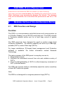
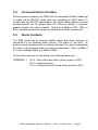
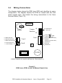
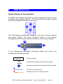
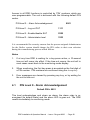
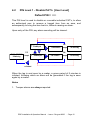
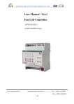
ParSec
Data Display &
Entry Panel (DDE)
INSTALLATION &
USER MANUAL
This page is intentionally blank
ParSec Data Display & Entry Panel (DDE)
INSTALLATION & USER MANUAL
Part No:
UM016
Document No: A/UM 230 851
Issue Draft 5
August 2000
Newmark Technology Ltd
21-23, Ormside Way
Redhill
Surrey
RH1 2NT
United Kingdom
Tel: +44(0) 1737 788800
Fax: +44(0) 1737 779535
Web site: www.newmarkworld.com
DDE Installation & Operation Manual - Issue: 5 August 2000
- Page 1
FCC Compliance Statement
These devices comply with part 15 of the FCC CFR 47 rules.
Operation is subject to the following two conditions:
(1)
These devices may not cause harmful interference, and
(2)
These devices must accept interference received, including
interference that may cause undesired operation.
The user is cautioned that modifications or changes to an
intentional or unintentional radiator not expressly approved by the
party responsible for compliance could void the user's authority to
operate the equipment.
The DDE contains a standard Lithium coin cell and as such the
following warning shall be noted:
CAUTION
Danger of explosion if batteries are incorrectly replaced.
Replace only with the same or equivalent type recommended by
the manufacturer. Dispose of used batteries according to the
manufacturers instructions within this manual.
IMPORTANT NOTE
This manual should be read in conjunction with the ParSec
Reader manual IM016.
DDE Installation & Operation Manual - Issue: 5 August 2000
- Page 2
CONTENTS
1
Caution - Static Precautions
2
General Installation & Guidance Notes
2.1
2.2
2.3
2.4
2.5
3
Installing the DDE
3.1
3.2
3.3
3.4
4
DDE Function & Design
Siting the DDE
Power Supply Requirements
Communications Interface
Alarm Contacts
Fixing the Enclosure
Wiring Connections
Ferrite Cores
Ferrite Installation and Wiring
DDE Operation
4.1
4.2
4.3
4.4
Pin Level 0 - Alarm Acknowledgement
Pin Level 1 - Disable PAT's
Pin Level 2 - Disable SAT's
Pin Level 3 - Administration Level
4.4.1 PAT Options
4.4.2 SAT Options
4.4.3 System Options
4.4.4 Reset Options
4.4.5 Print Options
4.4.6 Alarm Options
4.4.7 Change PIN Numbers
5 Commissioning the system
5.1
5.2
5.3
5.4
Power Up
Default SAT Pulse Count
Monitoring Mode
Commissioning Procedure Summary
DDE Installation & Operation Manual - Issue: 5 August 2000
- Page 3
6 Trouble shooting
6.1 System Self-test
6.2 Tags Not Being Reported
6.3 Loss of Data
7 Repair
8 Technical Specification
9 Change Record
DDE Installation & Operation Manual - Issue: 5 August 2000
- Page 4
1
CAUTION- STATIC PRECAUTIONS
Some devices used within the DDE are sensitive to static electricity.
Anti-static precautions must be taken when handling the printed circuit boards.
Static discharge may permanently damage the boards. The damage
may not be immediate, but could affect the performance and life of the
unit.
2
GENERAL INSTALLATION AND GUIDANCE NOTES
2.1
DDE Function and Design
Function
The DDE is a microprocessor-controlled device and communicates up
to 9-ParSec Readers via an RS-232 serial data port. The DDE includes
a Centronics parallel printer port for a hard copy record of system
events.
The DDE panel has been designed for small to medium sized Asset
Protection installation. Its memory capability will store up to 200 tags,
portable (PAT's) and/or Static tags (SAT's).
For larger installations, PC-based Asset management and Protection
software is available. For further information contact Newmark
Technology.
The main purposes of the DDE panel in everyday use are to;
1. Report alarm events.
2. Facilitate the authorised removal from site and validate re-entry of
PAT's.
3. Permit enabling/disabling of SAT's to allow temporary movement of
SAT- protected assets.
The DDE also has the ability to individually adjust the motion sensitivity
of each SAT within the system.
Note:
The DDE is not designed to recognise personnel tags (PET's).
DDE Installation & Operation Manual - Issue: 5 August 2000
- Page 5
ALARM
POWER
1
2
3
4
5
6
7
8
9
REJECT
0
ACCEPT
Figure 1
Data Display & Entry panel
shown with front panel open & closed
DDE Installation & Operation Manual - Issue: 5 August 2000
- Page 6
Design
The DDE consists of a hinged all metal housing which provides
protection and security to the internal Logic Printed Circuit Board (PCB).
The front panel comprises a 2-line x 20 character back-lit LCD panel, on
which alarms and status information are displayed, and a numeric
membrane keypad for system configuration and tag control. The front
panel also includes two LED's that indicate power on (green) and an
alarm (red).
The DDE front cover is normally supplied with standard M3 x 10mm
long cross head screws, which may be replaced by security or “Torx”
head screws. Newmark provide these alternative security screws with
every unit. To use these alternative fixings you will require the following
tools; “Torx” type TX10 screwdriver or a Newmark security driver (Part
no SS0001).
Any attempt to remove the front cover will operate the internal antitamper switch that may be used to trigger a local or remote alarm.
The housing rear panel provides wall mounting points, cable entry holes
and a chassis earth/ground point.
The DDE logic PCB is mounted on the rear of the hinge-down front
panel and permits easy access to the connection terminals and
components for installation and maintenance.
DDE Installation & Operation Manual - Issue: 5 August 2000
- Page 7
2.2
Siting the DDE
Caution
Because the DDE is housed within a metal box, if mounted
in close proximity to a ParSec reader it may affect the
performance of that reader.
The DDE will normally be sited in a secure area or for convenience near
the exit, which is being monitored by ParSec Readers. To permit the
logging out of tagged assets. It should be mounted at a convenient
height to allow easy operation of the keypad in conjunction with a clear
view of the LCD display.
If you wish to use the PAT log-out facility whilst carrying the tagged
asset, the DDE must be located outside the PAT Protected Reader
zone to enable correct operation of the system.
If the DDE is to be used purely for monitoring and the log-out facility is
not required; the unit may be mounted in a location convenient to the
designated administrator of the asset protection system.
For an installation where there are multiple Readers, the DDE should be
located in a conveniently central location.
The DDE is screened and requires no special precautions for protection
against electromagnetic interference, other than proper grounding.
2.3
Power Supply Requirements
The DDE requires a 12V/150mA, DC power supply, which must be CE
or other local authority approved.
Power to the DDE may optionally be derived from an adjacent ParSec
Reader, in which case use a suitable shielded cables e.g. 2-core Belden
8760.
It is recommended that power and signal cables to the DDE should be
separated from 3-phase mains supplies by at least 1 metre and from
single phase main supplies and all other types of cable runs by at least
0.5 metres.
The DDE is equipped with an internal lithium battery to protect the
stored data for a period of one month. If power is removed from the
DDE for longer than this all its data may be lost.
DDE Installation & Operation Manual - Issue: 5 August 2000
- Page 8
2.4
Communications Interface
Communication between the DDE and its associated ParSec Reader(s)
is made via an RS-232 serial data link operating at 2400 baud. To
comply with the RS-232 specification, the signal cable between the two
devices should not be greater than 60 metres in length; in practice,
greater lengths are often possible. Use 2-core Belden 8761, 9841 or
9501. Always connect the screen to earth/ground at the remote end.
2.5
Alarm Contacts
The DDE panel has an internal audible alarm and relay contacts for
connection to an external alarm device. The alarm is ‘fail safe’, i.e.
during normal operation with no alarms activated, the relay is energised;
the relay is de-energised when an alarm is generated. Use a suitable 2
or 3-core shielded cable, e.g. Belden 9533.
Terminal connections for the wiring of an external alarm are;
TERMINAL 1
Pin 6 - Relay Normally Open (when power is OFF).
Pin 5 - Relay Common.
Pin 4 - Relay Normally Closed (when power is OFF).
DDE Installation & Operation Manual - Issue: 5 August 2000
- Page 9
This page is intentionally blank
DDE Installation & Operation Manual - Issue: 5 August 2000
- Page 10
3
INSTALLING THE DDE
3.1
Fixing the DDE Enclosure
The case should be fixed in position with appropriate screws (No 6 or
No 8) in the upper two Keyhole mounting points, and secured with a
third screw in the lower slotted hole. The location of the 3-cable entry
holes (A) and the chassis earth point (B) must also be taken into
consideration prior to permanently mounting the DDE.
152
10
31
42
90
31
10
11
A
133
150
127.5
210
A
A
B
45
CABLE ENTRY
HOLE 'A'
IN 3 POS'NS
CHASSIS
EARTH
GROUND
Figure 2 Fixing Details
DDE Installation & Operation Manual - Issue: 5 August 2000
- Page 11
3.2
Wiring Connections
The diagram below shows the DDE logic PCB and identifies its major
components. The diagram depicts the PCB as viewed with the front
panel hinged open, and shows the wiring connections to the three
terminal blocks (Term 1-3).
PL2
Battery
3 - RS232 Ground
2 - RS-232 Receive In
1 - RS232 Transmit Out
Term3
*
2 - Power supply 0V
1 - Power Supply + 12V
Tamper
Switches
S1
S1 Reserved for
future use
S3
Term1
1
1
Term2
EPROM
1
S3
8 Tamper
Normally
7 Tamper closed
6 Relay NO (Power OFF)
5 Relay C
4 Relay NC (Power OFF)
3 Reserved
2 Ground
1 Reserved
Sounder
* RS232 Transmit out ( used for self-test only. See section 6.1)
FIGURE 3
DDE LOGIC PCB LAYOUT & WIRING CONNECTION
DDE Installation & Operation Manual - Issue: 5 August 2000
- Page 12
Term 2-6 (0V)
Term 2-5 (Tx)
Term 2-5 (Tx)
Term 3-2 (Rx)
Term 2-4 (Rx)
Term 2-5 (Tx)
Reader 1
Reader 2
Up to Reader 9
Term 2-6 (0V)
Term 2-6 (0V)
Term 2-4 (Rx)
Belden 8761,9841 or 9501
Term 3-3 (0V)
DDE
Optional DDE alarm relay
and/or tamper switch
connections to intruder alarm
panel, beacon or sounder etc.
Optional event printer (Dot-matrix)
FIGURE 4
DDE TO READER RS232 WIRING CONNECTIONS
DDE Installation & Operation Manual - Issue: 5 August 2000
- Page 13
3.3
Ferrite Cores.
WARNING
The DDE is supplied with 3 cylindrical ferrite cores, these must be fitted
to the cables entering or exiting the DDE. The Ferrite's are designed to
reduce the amount of radiated EMC transmissions from the unit and
MUST be fitted for it to conform to CE and FCC certification. Always
install the DDE wiring in accordance with this section. Newmark
Technology takes no responsibility for any unit installed incorrectly.
Of the 3 ferrite's supplied, 2 are physically the same shape and size,
these are used for the RS232 and RELAY contact cables prior to
termination. The third ferrite, which is physically larger, is used for the
entering POWER cable prior to termination.
You will notice that there are 3 cable entry holes in the DDE rear
chassis plate. When the unit is closed these holes correspond with the
3 terminal locations on the DDE processor PCB. Adjacent to each PCB
terminal is a threaded earth stud, which MUST be used to ground the
cable screen to the DDE chassis. These cable screens must be kept as
short as possible to obtain the best results.
Cable-tie bases are situated inside the unit to aid the location and
mounting the ferrite cores. Cable-ties have also been supplied to use
for retaining the ferrite's and cables once fitted.
IMPORTANT WIRING INFORMATION
The individual conductors of each cable must be fed through the ferrite
cores a number of times, this must be taken into account when
providing enough cable and removal of the outer insulation sleeve.
1. The POWER and RELAY conductor MUST pass 3 times through its
ferrite core before termination.
2. The RS232 DATA conductors MUST pass twice through its ferrite
core before termination.
3. The DDE unit chassis MUST be EARTHED.
DDE Installation & Operation Manual - Issue: 5 August 2000
- Page 14
This page is intentionally blank
DDE Installation & Operation Manual - Issue: 5 August 2000
- Page 15
3.4
Ferrite Installation and Wiring.
Fitting the ferrite's (See figure 5 & 6).
1. Feed the RS232 cable through the DDE chassis rear panel using the
appropriate hole (in this case bottom Left-hand side). Ensure there is
enough cable to reach terminal 3 and to feed through the ferrite core
twice (RS232 ONLY).
2. Strip back the outer insulating sleeve approx. 200mm (RS232
ONLY).
3. If your cable has an aluminium foil and shield drain wire, remove the
foil back to the outer insulation.
4. Twist the shield drain wire as tightly as possible and position the
cable so that the stripped back insulated section is as close as
possible to the relevant earth/ground stud.
5. Wrap the shield drain wire around the stud and secure using the nut
and washer provided. Once the cable is secure you can cut off the
excess shield drain wire.
Note: A suitable crimp or solder ring terminal can also be used to
terminate this shield drain wire. Remember to keep the length of this
wire as short as possible.
6. Feed the remaining conductors through the ferrite core the correct
number of times (in this case twice for RS232 cable).
7. Fit the cable ties to the cable tie bases, but do not loop or interlock
them.
8. Place the ferrite between the two cable tie bases adjacent to terminal
3 and adjust the cable by removing as much cable slack as possible
from either side of the ferrite.
9. Cut the individual conductors to the required length for termination.
10.Strip back approx. 5-6mm of the conductor insulation and terminate
the wires in accordance with section 3.2.
11. Loop and interlock the cable ties on either side of the ferrite and
secure the cable in place.
12. Remove the loose ends of the cable ties.
Repeat this procedure for the POWER and RELAY cables observing the
cable length and correct number of cable loops in parts 2 and 6
(3 times for POWER and RELAY cables).
DDE Installation & Operation Manual - Issue: 5 August 2000
- Page 16
Screened cable
Loop individual
conductors
Cable Tie &
Cable screen
earth stud
Terminal
Ferrite
Core
FIGURE 5
TYPICAL FERRITE CORE INSTALLATION
Chassis
Earth
Point
PL2
S1
S3
RS232
Ferrite
Core
1
Term3
(RS232)
Term2
1 (Power)
Earth Stud
In 3 positions
Relay
Ferrite
Core
Term1
(Relay)
1
Cable Tie & Base
In 6 positions
Power In
Ferrite
Core
FIGURE 6
FERRITE CORE POSITION
DDE Installation & Operation Manual - Issue: 5 August 2000
- Page 17
This page is intentionally blank
DDE Installation & Operation Manual - Issue: 5 August 2000
- Page 18
4
DDE OPERATION
General Notes & Conventions
The DDE user interface comprises a numeric keypad 0-9 with an Accept
and Reject key. Numeric keys 2, 4, 6 & 8 are dual function keys, bearing
arrows for navigation around the user menu.
1
2
3
4
5
6
7
8
9
REJECT
0
ACCEPT
The LCD display provides user feedback in the form of menu functions
and status reports. The arrow indicators shown on the display
correspond with the dual function arrow keys on the numeric keypad.
2
4
8
In the diagrammatic operating instructions within this section the
following conventions are used.
28-Mar-00 10:31
Monitoring
1234
Accept
6
LCD text display
indicates a key sequence should be entered
indicates a particular arrow key should be pressed
denotes normal logic flow
denotes incorrect or invalid logic flow
DDE Installation & Operation Manual - Issue: 5 August 2000
- Page 19
Access to all DDE functions is controlled by ‘PIN’ numbers, which are
user-programmable. The unit is delivered with the following default PIN
codes.
Ÿ PIN level 0 - Alarm Acknowledgement
0001
Ÿ PIN level 1 - Log out PAT
1111
Ÿ PIN level 2 - Enable/disable SAT
2222
Ÿ PIN level 3 - Administrator level
3333
It is recommended for security reasons that the person assigned Administrator
for the ParSec system should change the PIN codes to their own selection
during the commissioning process which follows.
Notes
1.
If at any time DDE is waiting for a key-press action, a 10-second
time-out will come into effect. If the time-out occurs, the unit will in
most cases revert back to the monitoring mode display.
2.
When monitoring, the first key-press is accepted as the first digit of
a PIN number. PIN numbers are confirmed using the Accept key.
3.
Error messages are cleared by pressing any key, or by waiting for
the unit to time-out.
4.1
PIN Level 0 - Alarm Acknowledgement
Default PIN = 0001
This level acknowledges and clears an alarm; the alarm relay is reenergised (its default state) and the alarm LED is goes out. The DDE
reverts immediately to monitoring mode.
DDE Installation & Operation Manual - Issue: 5 August 2000
- Page 20
4.2
PIN Level 1 - Disable PAT's [User Level]
Default PIN = 1111
This PIN level is used to disable or re-enable individual PAT's, to allow
an authorised user to remove a tagged item from an area, and
subsequently to bring the item back in, without causing an alarm.
Upon entry of the PIN, any alarm sounding will be cleared.
24
Enable pat
6
1111
29-Mar-00 10:30 Accept
Monitoring
2
Pat number?
8
Disable pat
Accept
No such tag
24
6
Pat number?
Accept
No such tag
4
or timeout
When the tag is next seen by a reader, a grace period of 5 minutes is
initiated, following which an alarm will be generated if the tag is seen
again by a reader.
Notes
1. Tamper alarms are always reported.
DDE Installation & Operation Manual - Issue: 5 August 2000
- Page 21
4.3
PIN Level 2 – Disable SAT's
Default PIN = 2222
This level is used to disable and re-enable individual SAT's, when the
asset protected by the SAT is to be moved, for example, for
maintenance purposes.
24
enable sat
6
2222
29-Mar-00 10:30 Accept
Monitoring
2
Sat number?
Accept
8
disable sat
no such tag
24
6
Sat number?
Accept
no such tag
4
or timeout
Note
1. Tamper alarms are always reported, even if a SAT has been
disabled.
DDE Installation & Operation Manual - Issue: 5 August 2000
- Page 22
4.4
PIN Level 3 - Administration Level
Default PIN = 3333
This PIN is used to access all system functions (any alarm sounding will
be cleared).
print options
alarm options
logout options
change pins
Status v3
29-Mar-00 10:31 3333
P-Y S-Y A-Y T=006
Monitoring
Accept
pat options
sat options
system options
reset options
DDE Installation & Operation Manual - Issue: 5 August 2000
- Page 23
The system status is displayed, comprising
• Software version number:
V X.X
Where X.X = The version of software fitted
• PAT's, SAT's & Alarms enabled (disabled): P-Y S-Y A-Y
For example;
P-Y means all PAT's are enabled (Y = Yes, N = No).
S-Y means all SAT's are enabled (Y = Yes, N = No).
A-Y means the DDE alarm is enabled (Y = Yes, N = No)
• Total number of tags recognised by the DDE:
T=NNN
Where NNN = the Total number of tags programmed into the DDE
(SAT's and PAT's combined)
All other system functions are available from this level by scrolling
through the menu options, and described in the following sections.
DDE Installation & Operation Manual - Issue: 5 August 2000
- Page 24
4.4.1 PAT Options
This function enables PAT's to be acquired by the DDE, and
subsequently deleted if required.
delete pats
2
or time out
4
pat options
2
6
6
PAT number?
11
Accept
no such tag
8
acquire pats
6
finding pats . . .
found pat
p11
8
3333
29-Mar-0010:31
Monitoring
Accept
Accept
Reject
status
p-y s-y a-y t=006
Present to Reader
PAT Options
DDE Installation & Operation Manual - Issue: 5 August 2000
- Page 25
4.4.2 SAT Options
This function enables SAT's to be acquired by the DDE, and
subsequently deleted if required.
The sensitivity of all SAT's may also be adjusted individually, by altering
the number of reports (‘pulse counts’) before the DDE initiates an alarm
condition for a particular SAT. This can be used to prevent false alarms
from accidental activation of the tag motion sensor caused by, for
example, a cleaner.
99
Accept
no such tag
5
24
modify sats
2
or timeout
4
sat options
2
8
6
sat number?
6
finding sats . . .
Accept
pulse count?
found sat
8
24
status v2.2
p-y s-y a-y t=006
Accept
delete sats
Accept
Reject
3333
29-Mar-00 10:31
Monitoring
Accept
8
acquire sats
2
6
6
sat number?
SAT Options
Accept
no such tag
Switch on SAT
and present to
Reader
The pulse count can be set from 1 to 9. UK SAT1's normally transmit 4
pulses at 1.5 second intervals, each time the tag motion sensor is
activated. FCC SAT2 tags transmit 7 pulses at 0.7 second intervals.
So setting the pulse count between 1 and 4 for a UK SAT1 tag only
delays the alarm activation by up to 5 seconds. Setting the pulse count
to 5 for a UK SAT1 will prevent a single activation of the motion sensor
causing an alarm.
Setting the pulse count to 8 for an FCC SAT2 tag will have the same
effect. To reduce sensitivity still further it is possible to use a
combination of DDE setting and reader adjustment (switch S9).
The previous statements assume that the reader pulse count switch is
set to position 0 or 1.
DDE Installation & Operation Manual - Issue: 5 August 2000
- Page 26
The following table illustrates how the various combinations of reader
and DDE pulse counts can be used.
Reader
S9
2
DDE
Pulse
count
4
Effective
Pulse
count
8
2
5
10
2
6
12
2
7 to 9
14 to 18
3
4
12
3
5
3
3
3
3
UK SAT1
FCC SAT2
1 motion sensor
activation ignored
1 motion sensor
activation ignored
1 motion sensor
activation ignored
15
1 motion sensor
activation's ignored
2 motion sensor
activation's ignored
2 motion sensor
activation ignored
Do not use. Disables
all tag activity.
2 motion sensor
activation's ignored
Do not use
6
7
8
18
21
24
Do not use
Do not use
Do not use
Do not use
Do not use
9
27
Do not use
Do not use
1 motion sensor
activation ignored
2 motion sensor
activation's ignored
3 motion sensor
activation's ignored
Do not use
It is important to note that the DDE counts pulses in a 15 second time
period. Therefore the number of tag sensor activation's allowed must
not be exceeded within this 15 second period. After this 15 second
period the counter is reset to zero.
These combinations are also valid for the global default SAT pulse
count settings.
DDE Installation & Operation Manual - Issue: 5 August 2000
- Page 27
4.4.3 System Options
The following system options are provided
• Set date & time
• Set default SAT pulse count - the global sensitivity setting for all
SAT's subsequently acquired except those programmed individually
(see SAT options); the count may be set between 1 & 9 pulses, with
1 giving the maximum sensitivity; this setting should ideally be made
before SAT's are acquired. Switch S9 on the ParSec reader maybe
used in combination with the DDE pulse count. (See section 4.2.2
for more details)
• Disabling and re-enabling alarms from all PAT's (tamper alarms are
not disabled)
• Disabling and re-enabling alarms from all SAT's (tamper alarms are
not disabled)
0201971140
set time
2
or time out
4
3333
29-Mar-00 10:31
Monitoring
Accept
system options
2
8
status v2.2
p-y s-y a-y t=006
6
6
pulse count?
1
Accept
5
8
disable all pats
2
Accept
8
default pulses
2
6
enter date/time
dd/mm/yy hh:mm
Accept
enable all pats
8
disable all sats
Accept
enable all sats
System Options
Note
1. When all PAT or SAT alarms have been disabled, no alarm will be
generated from the DDE when PAT or SAT transmissions are
detected by a Reader; to ensure system integrity the PAT or SAT
alarms should be re-enabled as soon as possible.
DDE Installation & Operation Manual - Issue: 5 August 2000
- Page 28
4.4.4 Reset Options
This function clears the DDE tag memory of all logged PAT's and SAT's
Use with caution!
or time out
4
Reset options
2
29-Mar-00 10:31
Monitoring
3333
Accept
6
8
Status v3.x
P-Y S-Y A-Y T=006
Clear Tag Table
2
Accept/
Reject
8
Clear Event Log
Reset Options
Note- Clearing the Event Log clears all the events stored in the Print
Log (Up to 50 events).
DDE Installation & Operation Manual - Issue: 5 August 2000
- Page 29
4.4.5 Print Options
The DDE logs events continuously. If a Centronics parallel printer is
connected to the DDE’s printer port, the following reports will be printed
1. Event log - comprising the last 50 events logged by the DDE,
including tag alarms, PAT's logged out/in, SAT's disabled/enabled
and all system events
2. Tag table - the identity of all PAT's and SAT's acquired by the DDE
and stored in its tag memory.
print log
2
or time out
4
3333
29-Mar-00 10:31
Monitoring
Accept
print options
2
6
Accept
8
print tags
Accept
8
status v2.2
p-y s-y a-y t=006
Print Options
Notes
1. The event memory is cleared when the event log is printed; if less
than 50 events have occurred since the previous printout, only
those events will be printed
2. If more than 50 events occur, the earliest events will be overwritten.
3. The tag log lists the tags in acquired order, not in tag number order.
4. Only dot matrix type printers are supported. Inkjet and laser printers
are not suitable.
DDE Installation & Operation Manual - Issue: 5 August 2000
- Page 30
4.4.6 Alarm Options
Facilities are provided to
• Globally disable and re-enable all alarms, both internal and
external, including tamper alarms
• Set the length of time that the alarm LED and sounder operate and
the alarm relay de-energises after a tag alarm has been generated;
note that the alarms will be silenced for a time equal to their on
period
set alarm period
2
or timeout
4
3333
29-Mar-00 10:31
Monitoring
Accept
alarm options
2
6
6
enter00period
00
01
Accept
invalid period
8
disable alarms
Accept
enable alarms
8
status v2.2
p-y s-y a-y t=006
AlarmOptions
Notes
1. A setting of 0 gives an alarm time of 5 seconds
2. Any other numbers entered are set as minutes (e.g. for 15 minutes
enter 15)
DDE Installation & Operation Manual - Issue: 5 August 2000
- Page 31
4.4.7 Change PIN numbers.
This facility is provided to change the PIN codes of Levels 0, 1, 2 & 3.
Re-entry invalid
2345
Accept
0, 1, 2 or 3
Accept
or time out
4
3333
29-Mar-00 10:31
Monitoring
Accept
change pins
2
6
access level?
1234
Accept
enter new pin
????
1234
Accept
Re-enter new
????? pin
8
status v2.2
p-y s-y a-y t=006
Change PINs
Note.
1. PIN codes must be a four-digit code.
DDE Installation & Operation Manual - Issue: 5 August 2000
- Page 32
5
Commissioning the System
5.1
Power Up
When power is initially applied to the DDE panel the display will read
Configuration Reset
If you now press the ACCEPT key, the DDE will display:DD/MMM/YY HH/MM
MONITORING
Notes
• If key 2 is depressed and held down before power is applied, the
DDE will perform a self-test routine (see section 6.1).
• If it is not practicable to switch off the mains power to perform the
self test, you can press the DDE master reset button on the main
processor PCB ref. S2.
• If the configuration is detected as corrupt at power-on, a
Configuration reset
Message is displayed, the configuration is reset to system defaults, and
the tag table is cleared (see section 5.2). No time-out applies to this
message.
5.2
Default SAT Pulse Count
The default SAT pulse count (see System Options, Section 4.4.3) must
be set before SAT's are acquired; if the setting is changed during
normal use of the DDE, the change will only be applied to SAT's
acquired after the change is made.
Note that the pulse count settings for individual SAT's as described in
section 4.4.2 will default to the global SAT pulse count
DDE Installation & Operation Manual - Issue: 5 August 2000
- Page 33
5.3
Monitoring Mode
The DDE is normally in monitoring mode. It displays date and time and,
if an alarm should occur, displays the tag number and “Alarm” or
“Tamper”, according to the type of alarm.
If an alarm occurs, the internal sounder is activated in high power mode,
the Alarm LED is illuminated, and the external alarm relay is deenergised.
The external alarm relay will remain de-energised until
1. the alarm times out, whereupon a silence period equal to the alarm
period is initiated, during which the external alarm will not be retriggered
2. A valid PIN is entered, which also clears down the internal sounder
and alarm LED; the alarm silence period in progress is also
cancelled.
The original alarm will not be re-reported until the tag causing the alarm
has been removed from the reader’s detection range for at least 15
seconds.
If another tag alarms, it will be reported as soon as the original alarm is
cleared by entering a PIN. However, there is no queue of tags in the
DDE so only the last tag will be reported if several tags alarm at the
same time.
5.4
1.
Commissioning Procedure Summary
Apply power, check the DDE displays
DD/MMM/YY HH/MM
MONITORING
2.
3.
4.
5.
6.
7.
Set Date & Time
Set default SAT pulse count (if SAT's are to be used)
Acquire SAT's (if used)
Acquire PAT's (if used)
Print tag table to confirm all required tags have been acquired
Set Alarm time
DDE Installation & Operation Manual - Issue: 5 August 2000
- Page 34
8.
9.
Change PIN numbers if required
Verify the system status to check that SAT's, PAT's and Alarms are
enabled (as appropriate) and that the total tag count is correct.
Notes
1. PAT's should be acquired before attachment to assets; they may be
switched off temporarily as the DDE will retain their identity
2. A manual log must be made of the assets to which tags are
attached to enable tag alarms to be traced
3. Tags must be switched on (switch 1) before being affixed to the
asset!
4. If hourly routine reporting is required from any or all tags, switch 4
must be set ON before switching the Tag ON and affixing it.
5. If new tags are introduced to the system, they must be individually
acquired
6. If there is more than one Reader in the system, tags may be ‘shown’
to any Reader to be acquired by the DDE.
7. PIN numbers and PAT/SAT numbers should be kept confidential to
maintain system security
8. Changed PIN numbers should be carefully recorded to maintain
appropriate access to the system
9. If the default SAT pulse count is changed during normal use of the
DDE, the new count is only applied to SAT's acquired after the
change (see Section 4.4.3 – System Options).
DDE Installation & Operation Manual - Issue: 5 August 2000
- Page 35
This page is intentionally blank
DDE Installation & Operation Manual - Issue: 5 August 2000
- Page 36
6
TROUBLESHOOTING
6.1
System Self-test
Operation
•
•
•
•
Turn off power to DDE for 20 seconds.
Loop RS-232 Tx & Rx on terminal block (Term 3 pins 1 & 2)*
Press and hold down key 2 whilst re-applying power.
DDE will perform self-test with numerous functions including a
keypad test requiring operator interaction, a test of the LED's and
sounder, real time clock, alarm relay and RS232 port. The operator
will be prompted at each stage, normally by pressing the ACCEPT
key.
If the DDE is working correctly, the DDE will display.
System OK
*If it is not convenient to perform this step, the self-test may still
be run, but the final test for the RS232 port will not be tested
and you will see.
System faulty
• Should the system faulty display arise at any other point in the test,
contact your supplier.
6.2
Tags not being reported
Checklist
• Print tag table to check tag has been acquired
• Display system status to check SAT's and PAT's are enabled, as
required
• Ensure tag was switched ON before being affixed to asset!
• Wait at least 15 seconds before attempting to test the same Tag
twice.
DDE Installation & Operation Manual - Issue: 5 August 2000
- Page 37
6.3
Loss of Data
If the DDE memory becomes corrupted the following effects may be
observed
• The date/time display is corrupted
• The display ‘pulsates’
Perform the following corrective action
• Remove power from the DDE
• Open the front panel and locate the back-up battery
• Insert a layer of insulation (the edge of a credit card is ideal)
between the battery spring clip and the battery itself for 20 seconds
• Reapply power and perform self-test if required
Note that all data will have been lost and it will be necessary to
perform full system re-commissioning (see Section 5.5).
DDE Installation & Operation Manual - Issue: 5 August 2000
- Page 38
7. Repair
If for any reason you wish to return the reader for repair or upgrade, before
shipping the reader call the Operations Department at Newmark on
+44 (0) 1737 788825 and obtain a Repair and Service number (RAS No.).
When calling, please have the following information available:
• Reason for return
• Reader serial number/ tag number.
• Our invoice or sales order number - if known
Mark the package with the RAS number and return it to;
Newmark Technology
Unit 6
Mercantile Road
Rainton Bridge Industrial Estate
Houghton Le Spring
County Durham
DH4 5PH
United Kingdom.
For products, which are no longer covered by our 12-month warranty, you will
need to order new or replacement components.
The information in this document is subject to change without notice and
should not be construed as a commitment by Newmark Technology Limited.
No responsibility is assumed by Newmark Technology Limited for any errors
that appear in this document.
No part of this document may be transmitted or reproduced in any form or by
any means, electronic or mechanical, including photocopy, recording or any
information storage or retrieval system without the express permission in
writing from Newmark Technology Limited.
DDE Installation & Operation Manual - Issue: 5 August 2000
- Page 39
This page is intentionally blank
DDE Installation & Operation Manual - Issue: 5 August 2000
- Page 40
8. Technical Specification
8.1
Dimensions: 210H x 152W x 42D in mm.
8.2
Weight:
8.3
Environmental
2.3kg
o
o
Operating Temperature: -5 C to +40 C
o
o
Storage Temperature: -10 C to +70 C
8.4
Electrical Power Supply
12Vdc (+/-3Vdc) at 150mA Max. Nominal 70mA.
8.5
Data input.
Industry standard RS232, 2400 baud.
For protocol, contact Newmark Technology.
8.6
Alarm Relay
• Single pole double throw voltage-free contacts, rated at
24V, 1A Max.
• Default output duration 5 seconds. Programmable up to 99
minutes.
• Operated by any valid asset tag data received in motion or
tamper, logged in the DDE memory.
8.7
Certification & Approvals.
• Meets or exceeds EN50081:1992 Emissions.
EN50082-1:1992 Immunity.
• FCC Part 15.231 parts (a) and (b), intentional radiators.
DDE Installation & Operation Manual - Issue: 5 August 2000
- Page 41
This page is intentionally blank
DDE Installation & Operation Manual - Issue: 5 August 2000
- Page 42
9. Change Record
Issue
5
Change
Date
Description of Change
Affected Sections
ECN 11193
August 2000
New Format
All Sections
The information in this document is subject to change
without notice and should not be construed as a
commitment by Newmark Technology Limited.
No responsibility is assumed by Newmark Technology
Limited for any errors that appear in this document.
No part of this publication may be transmitted or reproduced
in any form or by any means, electronic or mechanical,
including photocopy, recorded or any information storage or
retrieval system, without the express permission in writing
from the publisher.
DDE Installation & Operation Manual - Issue: 5 August 2000
- Page 43
Newmark Technology Ltd
21-23, Ormside Way
Redhill
Surrey
RH1 2NT
United Kingdom
Tel:
+44(0) 1737 788800
Fax:
+44(0) 1737 779535
Web site: www.newmarkworld.com