1
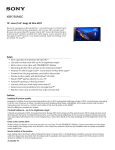
Freescale Semiconductor, Inc. Order this document as ROADRUNNERUM/D MOTOROLA SEMICONDUCTOR ARCHIVED BY FREESCALE SEMICONDUCTOR, INC 2005 Roadrunner Digital Camera System ARCHIVED BY FREESCALE SEMICONDUCTOR, INC. 2005 Freescale Semiconductor, Inc... APPLICATION NOTE USER MANUAL Rev 1.2 atory Motorola Image Capture Operation Chandler, AZ 1 MOTOROLA, Revision 1.2 – 05/06/01INC. 2001 Revision 04/12/01 This document contains information on a new product. Specifications and information herein are subject to change without notice For More Information On This Product, Go to: www.freescale.com Freescale Semiconductor, Inc. Order this document as ROADRUNNERUM/D MOTOROLA SEMICONDUCTOR APPLICATION NOTE ARCHIVED BY FREESCALE SEMICONDUCTOR, INC. 2005 Roadrunner Digital Camera System 1 1.0 – Hardware Setup 1.1 Cables 1.1.1 2 1.1.2 1.1.3 ARCHIVED BY FREESCALE SEMICONDUCTOR, INC. 2005 Freescale Semiconductor, Inc... Table of Contents Power Video Optics 1.2- Button Layout Description 1.2.1 Camera Mode: 1.2.2 Program/View Mode: 5 5 6 1.3- Led Display 1.4- Strobe Unit 7 1.5- Compact Flash Card 8 2.0 - NTSC Video Mode 2.1.1 THUMBNAIL 2.1.2 FULLSCREEN 2.1.3 DIRECTORY 2.1.4 SLIDE SHOW 2.1.5 DELETE ALL 2.2 2.3 2.4 2.5 INFO RECORD PROCESS ADVANCED 13 13 14 15 15 16 17 17 19 23 3.0 USB Mode 3.1 Twain 3.2 Using Twain Menu 4.0 Simple Operational Instructions 20 20 20 37 5.0 Contact Information 39 6.0 Hardware References 40 2 MOTOROLA, INC. 2001 Revision 04/12/01 For More Information On This Product, Go to: www.freescale.com Freescale Semiconductor, Inc. Order this document as ROADRUNNERUM/D MOTOROLA SEMICONDUCTOR APPLICATION NOTE ARCHIVED BY FREESCALE SEMICONDUCTOR, INC. 2005 1.0 HardWare Setup ARCHIVED BY FREESCALE SEMICONDUCTOR, INC. 2005 Freescale Semiconductor, Inc... Optional Strobe Module NTSC Video Cable USB Cable Figure 1.0 Basic Cable connection configuration Grooves Align Pins and push down GENTLY. a) Place Image head on Interface Board So that the Grooves align accordingly. b) Position boards in order that the pins on both the Sensor Interface board and the Sensor Board So align accordingly. Then push downward gently until cannot push down anymore. Figure 1.1 Image Head Mounting 3 MOTOROLA, INC. 2001 Revision 04/12/01 For More Information On This Product, Go to: www.freescale.com Freescale Semiconductor, Inc. Order this document as ROADRUNNERUM/D MOTOROLA SEMICONDUCTOR APPLICATION NOTE ARCHIVED BY FREESCALE SEMICONDUCTOR, INC. 2005 1.1.1 Power Power is supplied to the system via 3 x 1.5 Volt AA Batteries. The system uses a linear voltage regulator to supply the system with 3.1V to 3.8V @ ~250-400mA. Please don’t reverse the batteries – No protection!!. This system is capable of viewing a still image on a NTSC monitor through a sub mini micro stereo connector on the side of the system. The video is compatible with NTSC (American Television) and has capabilty for PAL as well. A 75 ohm cable is supplied with the system for connection to a TV/Monitor. ARCHIVED BY FREESCALE SEMICONDUCTOR, INC. 2005 Freescale Semiconductor, Inc... 1.1.2 Video 1.1.3 Optics The system has the ability to use 10mm, 12mm and “C” mount optics. This is done by using one of 3 different optic housing that bolts to the main PCB. The system comes equipped with 12mm fixed focus plastic optic. “C” mount optic or additional fixed focused optic can be requested from the factory. (For more Info – refer to Optical application Note @ www.motorola.com/adc/imaging) 4 MOTOROLA, INC. 2001 Revision 04/12/01 For More Information On This Product, Go to: www.freescale.com Freescale Semiconductor, Inc. Order this document as ROADRUNNERUM/D MOTOROLA SEMICONDUCTOR APPLICATION NOTE ARCHIVED BY FREESCALE SEMICONDUCTOR, INC. 2005 1.2 Button Layout/Description BUTTON ARCHIVED BY FREESCALE SEMICONDUCTOR, INC. 2005 Freescale Semiconductor, Inc... BUTTON 3 BUTTON 1 TOP VIEW BUTTON 2 Figure 1.1 Roadrunner Button Layout 1.2.1 Camera Modes There exists currently 3 modes in which the Roadrunner system can currently run : a) Still Camera mode – this mode allows for taking of pictures. - to be in this mode, both the USB and the Video cable have to be DISCONNECTED from the camera. b) NTSC Video mode –this mode allows for viewing of pictures taken as well as programming of certain different logic parameters while the camera is connected to NTSC Video monitor. -to be in this mode, ONLY the Video cable should be CONNECTED to the camera. c) -this mode allows for viewing of pictures taken as well as programming of certain logic parameters via the TWAIN Driver menu while the camera is connected to a computer via USB. -to be in this mode, ONLY the USB cable should be CONNECTED to the camera. USB Mode 1.2.2 SWITCH/BUTTON DESCRIPTION A) IN Picture Mode: (No USB or Video cable connected in Camera) i) BUTTON 1 - Power Button. ii) BUTTON 2 - CURRENTLY UNUSED in Camera mode. iii) BUTTON 3 - Strobe/Flash On/Off Switch in Camera mode. iv) BUTTON 4 - Shutter Button (ie. Click to take picture). 5 MOTOROLA, INC. 2001 Revision 04/12/01 For More Information On This Product, Go to: www.freescale.com 4 Freescale Semiconductor, Inc. Order this document as ROADRUNNERUM/D MOTOROLA SEMICONDUCTOR APPLICATION NOTE ARCHIVED BY FREESCALE B) IN NTSC Video Mode: (Only Video Cable SEMICONDUCTOR, connected to Camera) INC. 2005 i) BUTTON 1 - Power Button. ii) BUTTON 2 - CURRENTLY UNUSED in NTSC Video Mode. iii) BUTTON 3 - Menu Scroll button (ie. UP and DOWN scroll keys). iv) BUTTON 4 - Menu Select / Enter button. ARCHIVED BY FREESCALE SEMICONDUCTOR, INC. 2005 Freescale Semiconductor, Inc... C) IN USB Mode: (Only USB Cable connected to Camera) While in USB mode, all buttons on the Roadrunner system are INACTIVE. All camera functions are controlled via the USB TWAIN Graphical User Interface. 6 MOTOROLA, INC. 2001 Revision 04/12/01 For More Information On This Product, Go to: www.freescale.com Freescale Semiconductor, Inc. Order this document as ROADRUNNERUM/D MOTOROLA SEMICONDUCTOR APPLICATION NOTE ARCHIVED BY FREESCALE SEMICONDUCTOR, INC. 2005 1.2.3 Roadrunner Individual Boards: Backplane Board ARCHIVED BY FREESCALE SEMICONDUCTOR, INC. 2005 Freescale Semiconductor, Inc... Clarity 2 Processor Board Main SLA Chassis Sensor Interface Board Linear Power Supply Board SXGA Sensor Board 7 MOTOROLA, INC. 2001 Revision 04/12/01 For More Information On This Product, Go to: www.freescale.com Freescale Semiconductor, Inc. Order this document as ROADRUNNERUM/D MOTOROLA SEMICONDUCTOR APPLICATION NOTE ARCHIVED BY FREESCALE SEMICONDUCTOR, INC. 2005 1.3- LED DISPLAY 1.3.1 Location of the LED Clusters on the Roadrunner: * Note – On some Roadrunner Camera systems the LED cluster on the Processor board will be depopulated to conserve power. ARCHIVED BY FREESCALE SEMICONDUCTOR, INC. 2005 Freescale Semiconductor, Inc... Each LED cluster on the Roadrunner system contains 3 LEDs. They can be found on 3 different locations on the camera: i) The Button Board ii) The Processor Board * iii) The Sensor Backplane Interface Board. LED Cluster LEGEND LED IS OFF Led1 Led2 Led3 LED IS ON The following is a LED Lighting/Flashing Pattern flowchart explaination: (Explains how to determine what process is going on in the CAMERA based on what LEDS are ON or FLASHING) NOTE!! This pattern is applicable ONLY when Strobe/Flash is ON. For more info on the Strobe/Flash – see section 1.4. Process AUTO EXPOSURE IS STILL RUNNING (PICTURE CAN STILL BE TAKEN BUT EXPOSURE RATE MAY NOT BE SET YET) AUTO EXPOSURE IS SET – READY TO TAKE PICTURE! PROCESSING – WAIT UNTIL LED 2 STOPS FLASHING!. (APPROX. 15-20 SECONDS) 8 MOTOROLA, INC. 2001 Revision 04/12/01 For More Information On This Product, Go to: www.freescale.com Freescale Semiconductor, Inc. Order this document as ROADRUNNERUM/D MOTOROLA SEMICONDUCTOR APPLICATION NOTE ARCHIVED BY FREESCALE SEMICONDUCTOR, INC. 2005 1.4 Strobe Unit (Optional) The Strobe unit on the Roadrunner allows for the capturing of images in low lighting enviroments. In order to use the strobe unit on the Roadrunner: a) Version 5.005 and up of Firmware has to be loaded/programmed onto the Roadrunner system. (For more info on firmware downloads – refer to sections 1.5.2 and/or 3.3.4, ARCHIVED BY FREESCALE SEMICONDUCTOR, INC. 2005 Freescale Semiconductor, Inc... b) The Strobe mode must be switched on by either the TWAIN menu (see “FLASHMODE” – Section 3.3.3) or by pressing Button 3 until LED 3 illuminates. The following is a LED Lighting/Flashing Pattern flowchart explaination: (Explains how to determine what process is going on in the CAMERA based on what LEDS are ON or FLASHING) NOTE!! This pattern is applicable ONLY when Strobe/Flash is ON. Process AUTO EXPOSURE IS STILL RUNNING (PICTURE CAN STILL BE TAKEN BUT EXPOSURE RATE MAY NOT BE SET YET) AUTO EXPOSURE HAS DETECTED LOW LIGHTING. READY TO TAKE PICTURE WITH STROBE! PROCESSING – WAIT UNTIL LED 2 STOPS FLASHING! (APPROX. 15-20 SECONDS) . 9 MOTOROLA, INC. 2001 Revision 04/12/01 For More Information On This Product, Go to: www.freescale.com Freescale Semiconductor, Inc. Order this document as ROADRUNNERUM/D MOTOROLA SEMICONDUCTOR APPLICATION NOTE ARCHIVED BY FREESCALE SEMICONDUCTOR, INC. 2005 1.5 Compact Flash The Roadrunner has the capability of storing images onto a Compact Flash card instead of its internal Flash memory. The advantage of this is increased storage capacity. The Roadrunner has been tested and proven to work with Compact Fash cards in the range of 8Mbyte64Mbyte. Inserting a Compact flash card into the Roadrunner system automatically causes the system to automatically save all images onto the Compact Flash card. If the user requires that the images be stored on the Roadrunner camera systems memory, ensure that the card is removed from the Roadrunner system. ARCHIVED BY FREESCALE SEMICONDUCTOR, INC. 2005 Freescale Semiconductor, Inc... 1.5.1 Saving Images Onto Compact Flash: Clarity 2 Processor Board Compact Flash Card Connector Compact Flash Card (Top Side of Card) Figure 1.5 – Side View of Roadrunner Illustrating location of Compact Flash Card Connector 10 MOTOROLA, INC. 2001 Revision 04/12/01 For More Information On This Product, Go to: www.freescale.com Freescale Semiconductor, Inc. Order this document as ROADRUNNERUM/D MOTOROLA SEMICONDUCTOR APPLICATION NOTE ARCHIVED BY FREESCALE SEMICONDUCTOR, INC. 2005 1.5.2 Loading Camera Firmware Via Compact Flash Card NOTE!! In order for this function to work – please ensure that the firmware version running on the Roadrunner system is Version 5.004 and higher [ NOTE!! For instructions on Loading Camera Firmware VIA USB – see Section 3.3.4] In order to load a Binary firmaware (.BIN) file onto the Roadrunner system via Compact Flash Card the following procedure must be followed: (IMPORTANT - Please follow each step to its completion) ARCHIVED BY FREESCALE SEMICONDUCTOR, INC. 2005 Freescale Semiconductor, Inc... Compact Flash Firmware Update Procedure NOTE!! Make sure that the battery in the camera is new. If battery dies during firmware update, the FLASH Memory will be permanently corrupted. Step 1) Copy the firmware update file (*.bin) to the Compact Flash Card. Step 2) Turn on the power on the camera (USB cable should not be attached) Step 3) Plug in Compact Flash Card Step 4) LED 2 on the Roadrunner system should flash as a rapid pace (see Section 1.3). This indicates that the Roadrunner has identified a Firmware binary file on the Compact Flash card and has started the update process. Step 5) Wait for at least 3 mins or until LED 1 on the Roadrunner has illuminated again. Step 6) Cycle the Power on the Roadrunner. Step 7) To ensure that the update has taken place – connect the camera to the PC via USB. Then via the TWAIN menu (see section 3.2) - Click on “Check status” to verify connectivity between the camera and PC via the USB. (If status indicates no connection – check cable connection and try again ) NOTE!! If no connection cannot be obtained between the camera and PC, DON’T GO ANY FURTHER. 11 MOTOROLA, INC. 2001 Revision 04/12/01 For More Information On This Product, Go to: www.freescale.com Freescale Semiconductor, Inc. Order this document as ROADRUNNERUM/D MOTOROLA SEMICONDUCTOR APPLICATION NOTE ARCHIVED BY FREESCALE SEMICONDUCTOR, INC. 2005 2.0- NTSC Video Mode This mode is used to view the pictures stored in the camera`s memory. The camera can also be programmed in this mode. NOTE!! IF THE COMPACT FLASH CARD IS INSERTED INTO THE ROADRUNNER – ONLY FILES/IMAGES CONTAINED ON THE COMPACT FLASH CARD WILL BE DISPLAYED. ARCHIVED BY FREESCALE SEMICONDUCTOR, INC. 2005 Freescale Semiconductor, Inc... When the camera is turned on and is hooked into a NTSC monitor via a NTSC cable (i.e. is in Graphical User Interface mode – See section 1.2), the following menu is displayed on the monitor (see Figure 2.0 below): MAIN REVIEW INFO RECORD PROCESS SETUP ADVANCED Figure 2.0 Main programming Screen There are 6 choices that are available from this menu: 1) REVIEW 2) INFO 3) RECORD 4) PROCESS 5) SETUP 6) ADVANCED To make a selection, just HIGHLIGHT the selection using the SCROLL KEY (Button 3 – see section 1.2) and then press the SELECT/ENTER KEY (Button 4- see section 1.2). NOTE!! If there are no pictures in memory (i.e. No pictures have been taken) the first 3 selections : REVIEW, INFO and RECORD - will be UNAVAILABLE. 12 MOTOROLA, INC. 2001 Revision 04/12/01 For More Information On This Product, Go to: www.freescale.com Freescale Semiconductor, Inc. Order this document as ROADRUNNERUM/D MOTOROLA SEMICONDUCTOR APPLICATION NOTE ARCHIVED BY FREESCALE SEMICONDUCTOR, INC. 2005 2.1 REVIEW Selecting “REVIEW” from the Main menu brings up a menu/screen like the one below (see figure 2.1). From this Menu, there are a further 5 choices To make a selection, just HIGHLIGHT the selection using the SCROLL KEY (Button 3 – see section 1.2) - then press the SELECT/ENTER KEY (Button 4- see section 1.2). ARCHIVED BY FREESCALE SEMICONDUCTOR, INC. 2005 Freescale Semiconductor, Inc... REVIEW THUMBNAIL FULL SCREEN DIRECTORY SLIDE SHOW DELETE ALL DONE Figure 2.1 Review screen 2.1.1 THUMBNAIL STEP 1) Selecting “THUMBNAIL” from the “REVIEW” menu allows the user to view all the pictures contained in the camera memory in a SMALLER THUMBNAIL format. A maximum of 4 thumbnail pictures can be viewed on a single page/screen. (see Figure 2.1.1 below). STEP 2) To make a selection, just HIGHLIGHT the selection using the SCROLL KEY (Button 3 – see section 1.2) - then press the SELECT/ENTER KEY (Button 4- see section 1.2). This action will take you to the File info of that image. (See figure 2.1.1b) STEP 3) TO EXIT: Highlight “DONE” and press the SELECT/ENTER KEY (Button 4- see section 1.2). FILE INFO DELETE PICTURE #2 PICTURE #1 Select to Delete picture DONE Size of Picture/file PICTURE #3 DONE 47 KB MOT_0018 PICTURE #1 Name of Picture/file Figure 2.1.1a SELECTING A PICTURE-BRINGS UP “FILE INFO” ON THAT PICTURE Figure 2.1.1b 13 MOTOROLA, INC. 2001 Revision 04/12/01 For More Information On This Product, Go to: www.freescale.com Freescale Semiconductor, Inc. Order this document as ROADRUNNERUM/D MOTOROLA SEMICONDUCTOR APPLICATION NOTE ARCHIVED BY FREESCALE SEMICONDUCTOR, INC. 2005 2.1.2 FULLSCREEN STEP 1) Selecting “FULLSCREEN” from the “REVIEW” menu allows the user to view all the pictures contained in the cameras memory in a FULL PAGE/SCREEN format. i.e. 1 picture per page/screen (see Figure 2.1.2a below). ARCHIVED BY FREESCALE SEMICONDUCTOR, INC. 2005 Freescale Semiconductor, Inc... STEP 2) To make a selection, just HIGHLIGHT the selection using the SCROLL KEY (Button 3 – see section 1.2) - then press the SELECT/ENTER KEY (Button 4- see section 1.2). This action will take you to the File info of that image. (See figure 2.1.2b) STEP 3) TO EXIT: Scroll through pictures until the “DONE” screen appears - press the SELECT/ENTER KEY (Button 4- see section 1.2). FILE INFO DELETE Select to Delete picture DONE PICTURE #1 Size of Picture/file 47 KB MOT_0018 PICTURE #1 Name of Picture/file Figure 2.1.2a SELECTING A PICTURE-BRINGS UP “FILE INFO” ON THAT PICTURE Figure 2.1.2b 14 MOTOROLA, INC. 2001 Revision 04/12/01 For More Information On This Product, Go to: www.freescale.com Freescale Semiconductor, Inc. Order this document as ROADRUNNERUM/D MOTOROLA SEMICONDUCTOR APPLICATION NOTE ARCHIVED BY FREESCALE SEMICONDUCTOR, INC. 2005 2.1.3 DIRECTORY STEP 1) Selecting “DIRECTORY” from the “REVIEW” menu allows the user to view all the FILE NAMES of the pictures contained in the cameras memory (see Figure 2.1.3a below). STEP 2) To make a selection, just HIGHLIGHT the selection using the SCROLL KEY (Button 3 – see section 1.2) - then press the SELECT/ENTER KEY (Button 4- see section 1.2). This action will take you to the File info of that image. (See figure 2.1.3b) ARCHIVED BY FREESCALE SEMICONDUCTOR, INC. 2005 Freescale Semiconductor, Inc... STEP 3) TO EXIT: Highlight “DONE” and press the SELECT/ENTER KEY (Button 4- see section 1.2). FILE INFO MOT_0019.JPG MOT_0018.JPG DONE DELETE Select to Delete picture DONE Size of Picture/file 47 KB MOT_0018 PICTURE #1 Name of Picture/file 2.1.4 SLIDE SHOW Figure 2.1.3a SELECTING A PICTURE-BRINGS UP “FILE INFO” ON THAT PICTURE Figure 2.1.3b STEP 1) Selecting “SLIDE SHOW” from the “REVIEW” menu allows the user to view all the pictures contained in the ca1meras memory automatically in predefined intervals of 5-1 seconds. (see Figure 2.1.4a below). STEP 2) To make a selection while the Slide Show is going on, - then press the SELECT/ENTER KEY twice (Button 4- see section 1.2) – Once to STOP the show – Two to select the highlighted picture. This action will take you to the File info of that image. (See figure 2.1.4b) STEP 3) TO EXIT: 1) If Slide Show is complete - “DONE” - press the SELECT/ENTER KEY (Button 4- see section 1.2). 2) The FILE INFO page - Highlight “DONE” and press the SELECT/ENTER KEY (Button 4- see section 1.2). Note!! This will take you back to the Slide show – keep pressing the SELECT/ENTER KEY until you reach the screen that displays- “DONE” - press the SELECT/ENTER KEY (Button 4see section 1.2). 15 MOTOROLA, INC. 2001 Revision 04/12/01 For More Information On This Product, Go to: www.freescale.com Freescale Semiconductor, Inc. Order this document as ROADRUNNERUM/D MOTOROLA SEMICONDUCTOR APPLICATION NOTE ARCHIVED BY FREESCALE SEMICONDUCTOR, INC. 2005 FILE INFO DELETE Select to Delete picture DONE PICTURE #1,2,3,……. (switches every 1-5 sec’s) Size of Picture/file 47 KB MOT_0018 PICTURE #1 ARCHIVED BY FREESCALE SEMICONDUCTOR, INC. 2005 Freescale Semiconductor, Inc... Name of Picture/file Figure 2.1.4a 2.1.5 SELECTING A PICTURE-BRINGS UP “FILE INFO” ON THAT PICTURE Figure 2.1.4b DELETE ALL STEP 1) Selecting “DELETE ALL” from the “REVIEW” menu allows the user to delete all the PICTURES/FILES contained in the cameras memory (see Figure 2.1.5a below). STEP 2) To DELETE -HIGHLIGHT the “OK” selection using the SCROLL KEY (Button 3 – see section 1.2) - then press the SELECT/ENTER KEY (Button 4- see section 1.2). A Screen like Figure 2.1.5b will appear informing you that the CAMERA MEMORY is being FORMATTED. !! IMPORTANT NOTE - DO NOT SHUT DOWN CAMERA WHILE MEMORY FORMATTING IS IN PROCESS – DOING SO CAN CAUSE DAMAGE TO THE OPERATING SYSTEM. IF THIS OCCURS PLEASE CONTACT MANUFACTURER – SEE CONTACT INFO FOR DETAILS) STEP 3) TO CANCEL & EXIT: Highlight “CANCEL” and press the SELECT/ENTER KEY (Button 4see section 1.2). CONTINUE DELETE OF ALL IMAGES FORMATTING MEMORY OK CANCEL Figure 2.1.5a SELECTING “OK” – FORMATS THE CAMERA MEMORY Figure 2.1.5b 16 MOTOROLA, INC. 2001 Revision 04/12/01 For More Information On This Product, Go to: www.freescale.com Freescale Semiconductor, Inc. Order this document as ROADRUNNERUM/D MOTOROLA SEMICONDUCTOR APPLICATION NOTE ARCHIVED BY FREESCALE SEMICONDUCTOR, INC. 2005 2.2 INFO Selecting “INFO” from the Main menu brings up a menu/screen like the one below (see figure 2.2). The screen provides the following information to the user: BATTERY STATUS - please ignore this item until further notice. VERSION- lists the Software Version the camera is running. MEMORY- Gives approximate amount of Memory that : - has been used. - is currently free/not been used. - total memory. TO EXIT: Highlight “DONE” and press the SELECT/ENTER KEY (Button 4- see section 1.2). ARCHIVED BY FREESCALE SEMICONDUCTOR, INC. 2005 Freescale Semiconductor, Inc... 1) 2) 3) INFO BATTERY FULL VERSION 3.100 MEMORY USED 126 FREE 1397 SIZE 1523 DONE KB KB KB Figure 2.2 Info Screen 2.3 RECORD Selecting “RECORD” from the Main menu brings up a menu/screen like the one below (see figure 2.3). From this Menu, there are a further 2 choices: RECORD EXP FORMAT SAVE AUTO FINE Figure 2.3 Record Screen 17 MOTOROLA, INC. 2001 Revision 04/12/01 For More Information On This Product, Go to: www.freescale.com Freescale Semiconductor, Inc. Order this document as ROADRUNNERUM/D MOTOROLA SEMICONDUCTOR APPLICATION NOTE ARCHIVED BY FREESCALE SEMICONDUCTOR, INC. 2005 Freescale Semiconductor, Inc... BY FREESCALE SEMICONDUCTOR, INC.(Button 2005 3 – see section 1.2) To make a ARCHIVED selection, just HIGHLIGHT the selection using the SCROLL KEY - then press the SELECT/ENTER KEY (Button 4- see section 1.2). Choice 1) EXP – this allows the setting of the cameras Exposure rate. The more the exposure rate is, the more bright the picture will be, and vice versa (see Figure 2.3.1 below). There are 9 pre-set exposure rates that the user can choose from: (To scroll between these choices use the SCROLL KEY - then press the SELECT/ENTER KEY when ready to select the option.) a) AUTO : This causes the camera to automatically set the exposure level. b) AUTO-0.5 : REDUCES the automatic exposure level. c) AUTO-1.0 : Further REDUCES the automatic exposure level. d) AUTO-1.5 : Further REDUCES the automatic exposure level. e) AUTO-2.0 : Further REDUCES the automatic exposure level. f) AUTO+0.5 : INCREASES the automatic exposure level. g) AUTO+1.0 : Further INCREASES the automatic exposure level. h) AUTO+1.5 : Further INCREASES the automatic exposure level. i) AUTO+2.0 : Further INCREASES the automatic exposure level. NOTE!! Please keep this setting at AUTO at all times. AUTO-2.0 AUTO-1.5 AUTO-1.0 AUTO-.0.5 AUTO AUTO+0.5 AUTO+1.0 UNDER-EXPOSED AUTO+1.5 AUTO+2.0 OVER-EXPOSED Figure 2.3.1 Choice 2) FORMAT – this allows the setting of the PICTURE SIZES. There are 3 different sizes that the user can choose/select from: (To scroll between these choices use the SCROLL KEY - then press the SELECT/ENTER KEY when ready to select the option.) a) FINE b) ECONOMY c) ZOOM X2 - Approximately 640 X 480 pixels (largest size available) Approximately 320 X 240 pixels (smallest size available) Approximately 320 X 240 pixels (smallest size available) NOTE!! Selecting the ECONOMY and ZOOM X2 will produce the exact same sized image. SAVE & EXIT - Highlight “SAVE” and press the SELECT/ENTER KEY (Button 4- see section 1.2). 18 MOTOROLA, INC. 2001 Revision 04/12/01 For More Information On This Product, Go to: www.freescale.com Freescale Semiconductor, Inc. Order this document as ROADRUNNERUM/D MOTOROLA SEMICONDUCTOR APPLICATION NOTE ARCHIVED BY FREESCALE SEMICONDUCTOR, INC. 2005 2.4 PROCESS Selecting “PROCESS” from the Main menu brings up a menu/screen like the one below (see figure 2.4). From this Menu, there are a further 3 choices: ARCHIVED BY FREESCALE SEMICONDUCTOR, INC. 2005 Freescale Semiconductor, Inc... PROCESS JPG CONTRST WHITE 90 AUTO AUTO SAVE Figure 2.4 Process Screen To make a selection, just HIGHLIGHT the selection using the SCROLL KEY (Button 3 – see section 1.2) - then press the SELECT/ENTER KEY (Button 4- see section 1.2). Choice 1) JPG – This allows the setting of the JPG Compression level. The higher the number this is set at, the lower the compression level. There are 6 different choices that the user can choose/select from: (To scroll between these choices use the SCROLL KEY - then press the SELECT/ENTER KEY when ready to select the option.) a) b) c) d) e) f) 90 80 70 60 50 40 Each PICTURE/FILE Approx. 120KB SIZE QUALITY Each PICTURE/FILE Approx. 30KB Choice 2) CONTRST - This allows the setting of the CONTRAST level. The higher the level that this is set at, the more the contrast between the light and dark areas will be. (Less gamma correction is applied). There are 4 different choices that the user can choose/select from: (To scroll between these choices use the SCROLL KEY - then press the SELECT/ENTER KEY when ready to select the option.) The gamma correction is applied by using a exponential curve = X exp(VALUE) – depending on the “VALUE” we get different CONTRST (gamma correction settings) : a) AUTO : This causes the camera to automatically set the contrast level. (Low gamma correction) Curve = X exp(VALUE) -VALUE is determined by the camera b) HIGH : Will increase the contrast level of the picture taken. Curve = X exp(0.8) 19 MOTOROLA, INC. 2001 Revision 04/12/01 For More Information On This Product, Go to: www.freescale.com Freescale Semiconductor, Inc. Order this document as ROADRUNNERUM/D MOTOROLA SEMICONDUCTOR APPLICATION NOTE ARCHIVED BYaverage FREESCALE SEMICONDUCTOR, INC. 2005 NORMAL : Maintains level of contrast level of the picture taken. Curve = X exp(0.6) d) LOW : Will decrease the contrast level of the picture taken. (High gamma correction) Curve = X exp(0.45) c) ARCHIVED BY FREESCALE SEMICONDUCTOR, INC. 2005 Freescale Semiconductor, Inc... Choice 3) WHITE – This allows the setting of the cameras lighting environment. There are 6 different choices that the user can choose/select from: (To scroll between these choices use the SCROLL KEY - then press the SELECT/ENTER KEY when ready to select the option.) a) b) c) d) e) f) AUTO: FLRSCENT: TUNGSTEN: SUN: SHADE: OFF: This causes the camera to automatically set the lighting environment. Selected for Fluorescent lighting environments. Selected for Tungsten lighting environments. Selected for naturally sun lighted environments. Selected for shaded areas. Turns this setting off. NOTE!! Please leave this setting at AUTO. TO SAVE & EXIT - Highlight “SAVE” and press the SELECT/ENTER KEY (Button 4- see section 1.2). NOTE!! Please don’t forget to SAVE before exiting. 20 MOTOROLA, INC. 2001 Revision 04/12/01 For More Information On This Product, Go to: www.freescale.com Freescale Semiconductor, Inc. Order this document as ROADRUNNERUM/D MOTOROLA SEMICONDUCTOR APPLICATION NOTE ARCHIVED BY FREESCALE SEMICONDUCTOR, INC. 2005 2.5 SETUP Selecting “SETUP” from the Main menu brings up a menu/screen like the one below (see Figure 2.5). From this Menu, there are a further 6 choices: ARCHIVED BY FREESCALE SEMICONDUCTOR, INC. 2005 Freescale Semiconductor, Inc... SETUP TIMEOUT TV SHOW LANG RESTORE MORE… SAVE NONE NTSC 1 SEC ENGLISH DEFAULTS Figure 2.5 Setup screen To make a selection, just HIGHLIGHT the selection using the SCROLL KEY (Button 3 – see section 1.2) - then press the SELECT/ENTER KEY (Button 4- see section 1.2). Choice 1) TIMEOUT – this allows the setting of the cameras automatic Power down time. There are 5 pre-set auto shutoff times the user can choose from: (To scroll between these choices use the SCROLL KEY - then press the SELECT/ENTER KEY when ready to select the option.) a) b) c) d) e) 90 seconds automatic shutoff. 60 seconds automatic shutoff. 30 seconds automatic shutoff. 15 seconds automatic shutoff. NONE – No Auto power down. Choice 2) TV – this allows the setting of the Camera-Video monitor interface. There are 5 pre-set video monitor interfaces the user can choose from: (To scroll between these choices use the SCROLL KEY - then press the SELECT/ENTER KEY when ready to select the option.) a) b) c) d) e) NTSC PAL-B PAL-M PAL-N PAL-CN NOTE!! Has capability of supporting PAL video systems, but has not been tested. 21 MOTOROLA, INC. 2001 Revision 04/12/01 For More Information On This Product, Go to: www.freescale.com Freescale Semiconductor, Inc. Order this document as ROADRUNNERUM/D MOTOROLA SEMICONDUCTOR APPLICATION NOTE ARCHIVED BY FREESCALE SEMICONDUCTOR, INC. 2005 Choice 3) SHOW – this allows for the setting of the Slide Show time intervals (used in the REVIEW MODE). There are 5 pre-set time intervals that the user can choose from: (To scroll between these choices use the SCROLL KEY - then press the SELECT/ENTER KEY when ready to select the option.) ARCHIVED BY FREESCALE SEMICONDUCTOR, INC. 2005 Freescale Semiconductor, Inc... a) b) c) d) e) 5 Seconds 4 Seconds 3 Seconds 2 Seconds 1 Seconds Choice 4) LANG – this allows for the setting of the language used in the menus. There 4 pre-set languages that the user can choose from: (To scroll between these choices use the SCROLL KEY - then press the SELECT/ENTER KEY when ready to select the option.) a) b) c) d) English Francais Deutsche Espanol NOTE!! Please use English as the language. Other languages have not been tested. Choice 5) RESTORE DEFAULTS – this allows for the RESETTING of all the Menu items to DEFAULT values. To activate, press the SELECT/ENTER KEY when ready to restore the default values) NOTE!! This action will be carried out as soon as it is SELECTED. Does not need to be SAVED first before it takes action. Choice 6) MORE… -when selected, will bring up another screen, which will further give the user more choices. Choice 7) FORMAT- Formats the entire memory. TO SAVE & EXIT - Highlight “SAVE” and press the SELECT/ENTER KEY (Button 4- see section 1.2). 22 MOTOROLA, INC. 2001 Revision 04/12/01 For More Information On This Product, Go to: www.freescale.com Freescale Semiconductor, Inc. Order this document as ROADRUNNERUM/D MOTOROLA SEMICONDUCTOR APPLICATION NOTE ARCHIVED BY FREESCALE SEMICONDUCTOR, INC. 2005 2.6 ADVANCED Selecting “ADVANCED” from the Main menu brings up a menu/screen like the one below (see figure 2.6). From this Menu, there are a further 6 choices: ARCHIVED BY FREESCALE SEMICONDUCTOR, INC. 2005 Freescale Semiconductor, Inc... ADVANCED SAVE RAW SEE RAW MAX EXP CLR SAT DIG GAIN EXP CHNG SAVE OFF OFF 1.0 sec/default 0 percent/default 8.0/default 40 percent/default Figure 2.6 Advanced programming screen To make a selection, just HIGHLIGHT the selection using the SCROLL KEY (Button 3 – see section 1.2) - then press the SELECT/ENTER KEY (Button 4- see section 1.2). Choice 1) SAVE RAW – This allows the setting of the cameras RAW picture saving capability. When ON, the camera will save the RAW image as well as the JPG image. (To scroll between the ON/OFF choices use the SCROLL KEY - then press the SELECT/ENTER KEY when ready to select the option.) NOTE!! RAW images are significantly larger than the JPG images, and so when SAVE RAW is ON- it reduces the amount of memory/pictures that can be taken as compared to when it is turned OFF. Normally the camera has enough memory to save only 1 Raw image, but if you require to save 2 Raw images then turn the JPG compression to 50-40 *(see section 2.4 Choice 1). The time required by the camera to save the 1st Raw image is around 1 minute, while the 2nd one may take several minutes. Choice 2) SEE RAW – This allows the setting of the cameras RAW image viewing capability. When ON, the user will be able to view the RAW image. The image, however, when viewing it through the Video monitor will appear to be black – this is expected. However, this option also has to be turned ON, if the RAW images are to be downloaded and viewed on CAMERA DEMO. (To scroll between the ON/OFF choices use the SCROLL KEY - then press the SELECT/ENTER KEY when ready to select the option.) 23 MOTOROLA, INC. 2001 Revision 04/12/01 For More Information On This Product, Go to: www.freescale.com Freescale Semiconductor, Inc. Order this document as ROADRUNNERUM/D MOTOROLA SEMICONDUCTOR APPLICATION NOTE ARCHIVED BY FREESCALE SEMICONDUCTOR, INC. 2005 Freescale Semiconductor, Inc... ARCHIVED BY FREESCALE SEMICONDUCTOR, INC. 2005 Choice 3) MAX EXP – This allows the setting of the cameras Maximum Exposure time for the autoexposure algorithm (If the auto exposure routine determines that the exposure time needed is more than what the MAX EXP is set at, the algorithm will still be forced to use the MAX EXP value as its maximum exposure time). Theoretically, the more exposure time the camera is set at , the brighter the pictures will be. There 10 pre-set values that the user can choose from: (To scroll between these choices use the SCROLL KEY - then press the SELECT/ENTER KEY when ready to select the option.) a) 1 second maximum exposure / Default value. b) 0.5 second maximum exposure. c) 0.25 second maximum exposure. d) 0.1 second maximum exposure. e) 20 millisecond maximum exposure. f) 5 millisecond maximum exposure. g) 2.5 millisecond maximum exposure. h) 1 millisecond maximum exposure. i) 500 microsecond maximum exposure. j) 250 microsecond maximum exposure. Choice 4) CLR SAT - This allows the setting of the cameras Color Saturation level. Theoretically, the more saturated the colors are, the brighter/contrasted the individual colors become. There are 6 pre-set values that the user can choose from: (To scroll between these choices use the SCROLL KEY - then press the SELECT/ENTER KEY when ready to select the option.) NOTE!! Typical setting is around 20%-30% a) 0 percent / Default value b) 10 percent c) 20 percent d) 30 percent e) 40 percent f) 50 percent Choice 5) DIG GAIN - This allows the setting of the cameras digital gain level. This gain refers to the maximum gain that can be applied to the picture by the software – i.e. post sensor processing. There are 10 pre-set values that the user can choose from: (To scroll between these choices use the SCROLL KEY then press the SELECT/ENTER KEY when ready to select the option.) a) b) c) d) e) f) g) h) i) j) 1.0 2.0 3.0 4.0 5.0 6.0 7.0 8.0 / Default Value 9.0 10.0 Small Gain Large Gain 24 MOTOROLA, INC. 2001 Revision 04/12/01 For More Information On This Product, Go to: www.freescale.com Freescale Semiconductor, Inc. Order this document as ROADRUNNERUM/D MOTOROLA SEMICONDUCTOR APPLICATION NOTE SEMICONDUCTOR, INC. 2005change per frame by Choice 6) ARCHIVED EXP CHNG –BY ThisFREESCALE allows the setting of the cameras maximum exposure frame basis which is used determine the exposure time of the camera even when idle. The larger the value that this setting is set at, the quicker the time required by the camera to settle in on an appropriate exposure rate. Therefore, as expected the smaller the value the longer time is required. NOTE! There is a possibility of overshooting the expected exposure rate, if too larger a value is used in this setting. This will create either over or under exposed pictures. (To scroll between these choices use the SCROLL KEY - then press the SELECT/ENTER KEY when ready to select the option.) ARCHIVED BY FREESCALE SEMICONDUCTOR, INC. 2005 Freescale Semiconductor, Inc... NOTE!! Used as a place holder. Will be utilized later a) b) c) d) e) f) g) h) 0 percent 10 percent 20 percent 30 percent 40 percent / Default Value 50 percent 60 percent 70 percent 25 MOTOROLA, INC. 2001 Revision 04/12/01 For More Information On This Product, Go to: www.freescale.com Freescale Semiconductor, Inc. Order this document as ROADRUNNERUM/D MOTOROLA SEMICONDUCTOR APPLICATION NOTE ARCHIVED BY FREESCALE SEMICONDUCTOR, INC. 2005 3.0 USB Mode When in this mode, it allows the user to view pictures, as well as enables the programming of certain logic parameters via the latest USB TWAIN Driver (supplied by Motorola). To be in this mode, ONLY the USB cable should be CONNECTED to the camera. NOTE!! IF THE COMPACT FLASH CARD IS INSERTED INTO THE ROADRUNNER – ONLY FILES/IMAGES CONTAINED ON THE COMPACT FLASH CARD WILL BE DISPLAYED. The TWAIN driver menu enables the user to retrieve images directly from the Cameras flash memory. Its utilizes the USB connection as the main transport mechanism between the PC and Camera. ARCHIVED BY FREESCALE SEMICONDUCTOR, INC. 2005 Freescale Semiconductor, Inc... 3.1 Twain NOTE!! Although the TWAIN Driver can be installed and used on a variety of Graphics software programs, for demonstration purposes, this manual utilizes Camera Demo to illustrate the use of the TWAIN driver menu . (Camera Demo is a software application designed by Motorola to enable the end user to execute 4 key camera functions: control, capture, processing and analysis of camera images- a copy of Camera Demo software is available on the Roadrunner Installation CD or upon request). 3.2 Twain Menu Once the user has completed taking pictures and has attached the camera to a PC via USB and has opened up a graphics software application containing Motorolas Twain driver, in this case Camera Demo - To retrieve images from the camera using Twain, click on “Twain” from the main menu. Step 1) Select the “Select Source” from the Twain sub menu. Choose “Motorola Coyote Twain Driver” from the list of sources. Then press SELECT. (See figure 4-13 below) Figure 4-13 26 MOTOROLA, INC. 2001 Revision 04/12/01 For More Information On This Product, Go to: www.freescale.com Freescale Semiconductor, Inc. Order this document as ROADRUNNERUM/D MOTOROLA SEMICONDUCTOR APPLICATION NOTE ARCHIVED BY FREESCALE SEMICONDUCTOR, INC. 2005 ARCHIVED BY FREESCALE SEMICONDUCTOR, INC. 2005 Freescale Semiconductor, Inc... Step 2) Then select “Acquire” from the submenu. From this menu, there is a list of functions, which can be carried out, they are as follows: (See Figure 14-4 below) Figure 14-4 27 MOTOROLA, INC. 2001 Revision 04/12/01 For More Information On This Product, Go to: www.freescale.com Freescale Semiconductor, Inc. Order this document as ROADRUNNERUM/D MOTOROLA SEMICONDUCTOR APPLICATION NOTE ARCHIVED BY FREESCALE SEMICONDUCTOR, INC. 2005 3.3 Using The Twain Menu This section documents the various functions available via using the Twain Menu. The Twain Menu acts as the main user I/O between the Roadrunner and the PC via USB. The functions available via Twain menu are as follows: ARCHIVED BY FREESCALE SEMICONDUCTOR, INC. 2005 Check Camera Status – Displays the current status information for the camera. This screen can be used to tell if the Camera is online. Freescale Semiconductor, Inc... 3.3.1 Figure 1 4-5 3.3.2 Erase All Camera Files – Erases all images (Raw and Jpeg) in the camera. (see figure 14-6 below) Figure 14-6 28 MOTOROLA, INC. 2001 Revision 04/12/01 For More Information On This Product, Go to: www.freescale.com Freescale Semiconductor, Inc. Order this document as ROADRUNNERUM/D MOTOROLA SEMICONDUCTOR APPLICATION NOTE ARCHIVED BY FREESCALE SEMICONDUCTOR, INC. 2005 ARCHIVED BY FREESCALE SEMICONDUCTOR, INC. 2005 Change Camera Settings – Displays the current Image Capture Settings on the camera. It also allows the user to change and save some of these settings in real time while connected to the camera via USB. Note !! The Parameter/settings which can be changed are highlighted in White. Freescale Semiconductor, Inc... 3.3.3 Figure 14-7 NOTE- Placing the cursor over the Input Box of each item displays the different Input Value Options for each of the Image Capture Settings. [DON’T ENTER ANY OTHER VALUES OTHER THAN THE ONES PREDEFINED]. 1) AUTO_OFF – this allows the setting of the cameras automatic Power down time. There are 5 preset auto shutoff times the user can choose from: 01234- 90 seconds automatic shutoff. 60 seconds automatic shutoff. 30 seconds automatic shutoff. 15 seconds automatic shutoff. NONE – No Auto power down. 29 MOTOROLA, INC. 2001 Revision 04/12/01 For More Information On This Product, Go to: www.freescale.com Freescale Semiconductor, Inc. Order this document as ROADRUNNERUM/D MOTOROLA SEMICONDUCTOR APPLICATION NOTE ARCHIVED BY FREESCALE SEMICONDUCTOR, INC. 2005 2) NTSC_PAL_STATE – this allows the setting of the Camera-Video monitor interface. There are 5 pre-set video monitor interfaces the user can choose from: ARCHIVED BY FREESCALE SEMICONDUCTOR, INC. 2005 Freescale Semiconductor, Inc... 01234- NTSC PAL-B PAL-M PAL-N PAL-CN 3) SLIDE_SHOW - this allows for the setting of the Slide Show time intervals (used in the REVIEW MODE while reviewing images on the NTSC monitor – see section 2.0). The choices are any time intervals from 0 to 60 seconds 4) FLASHMODE – this allows for the Strobe module to be turned On or Off. When turned ON – the strobe will automatically be fired in low lighting conditions. The choices are as follows: 0Strobe Module Off 1Strobe Module On – automatically fires in low lighting environments. (Fires when Exposure time is approximately 170+ ms). 2Fill Flash- Not Supported 3Red Eye – Not Supported 5) GAMMA - This allows the setting of the CONTRAST level. The higher the level that this is set at, the more the contrast between the light and dark areas will be. (Less gamma correction is applied). There are 4 different choices that the user can choose/select from: The gamma correction is applied by using a exponential curve = X exp(VALUE) – depending on the “VALUE” we get different Contrast (gamma correction settings) : 0AUTO : This causes the camera to automatically set the contrast level Curve = X exp(VALUE) -VALUE is determined by the camera 1HIGH : Will increase the contrast level of the picture taken. Curve = X exp(0.8) 2NORMAL : Maintains average level of contrast level of the picture taken. Curve = X exp(0.6) 3LOW : Will decrease the contrast level of the picture taken. Curve = X exp(0.45) 6) JPEG - This allows the setting of the JPG Compression level. The higher the number this is set at, the lower the compression level. There are 6 different choices that the user can choose/select from: a) 90 b) 80 c) 70 d) 60 e) 50 f) 40 g) 30 h) 20 i) 10 7) IMAGE NUMBER INDEX – This allows the user to set what the next MOT_XXX image number will be. 30 MOTOROLA, INC. 2001 Revision 04/12/01 For More Information On This Product, Go to: www.freescale.com Freescale Semiconductor, Inc. Order this document as ROADRUNNERUM/D MOTOROLA SEMICONDUCTOR APPLICATION NOTE ARCHIVED BY FREESCALE SEMICONDUCTOR, INC. 2005 8) RES_FACTOR – This allows the user to select the size of the image being captured.0 Please don’t make any changes to this item at this time. 9) SPEAKER – Please don’t make any changes to this item. ARCHIVED BY FREESCALE SEMICONDUCTOR, INC. 2005 Freescale Semiconductor, Inc... 10) WHITE_BAL - This allows the setting of the cameras lighting environment. There are 6 different choices that the user can choose/select from: a) b) c) d) e) f) AUTO: FLRSCENT: TUNGSTEN: SUN: SHADE: OFF: This causes the camera to automatically set the lighting environment. Selected for Fluorescent lighting environments. Selected for Tungsten lighting environments. Selected for naturally sun lighted environments. Selected for shaded areas. Turns this setting off. 11) SAVE RAW – This allows the setting of the cameras RAW picture saving capability. When ON, the camera will save the RAW image as well as the JPG image. NOTE!! RAW images are significantly larger than the JPG images, and so when SAVE RAW is ON- it reduces the amount of memory/pictures that can be taken as compared to when it is turned OFF. Normally the camera has enough memory to save only 1 Raw image, but if you require to save 2 Raw images then turn the JPG compression to 50-40 *(see section 2.4 Choice 1). The time required by the camera to save the 1st Raw image is around 1 minute, while the 2nd one may take several minutes. 12) DOVFORMAT – Please don’t make any changes to this item – Default Value “0”. 13) MODEL DEPENDENT - Please don’t make any changes to this item – Default Value “0”. 14) SEE RAW – This allows the setting of the cameras RAW image viewing capability. When ON, the user will be able to view the RAW image. The image, however, when viewing it through the Video monitor will appear to be black – this is expected. However, this option also has to be turned ON, if the RAW images are to be downloaded and viewed on CAMERA DEMO. 15) SATURATION - This allows the setting of the cameras Color Saturation level. Theoretically, the more saturated the colors are, the brighter/contrasted the individual colors become. There are 6 pre-set values that the user can choose from: a) 0 percent / Default value b) 10 percent c) 20 percent d) 30 percent e) 40 percent f) 50 percent 16) MAX EXPOSURE - This allows the setting of the cameras Maximum Exposure time for the autoexposure algorithm (If the auto exposure routine determines that the exposure time needed is more than what the MAX EXP is set at, the algorithm will still be forced to use the MAX EXP value as its maximum exposure time). Theoretically, the more exposure time the camera is set at , the brighter the pictures will be. They’re 9 pre-set values that the user can choose from: 31 MOTOROLA, INC. 2001 Revision 04/12/01 For More Information On This Product, Go to: www.freescale.com Freescale Semiconductor, Inc. Order this document as ROADRUNNERUM/D MOTOROLA SEMICONDUCTOR APPLICATION NOTE BY FREESCALE SEMICONDUCTOR, INC. 2005 a)ARCHIVED 250 microseconds b) 500 microseconds c) 1000 microseconds d) 2500 microseconds e) 20000 microseconds f) 100000 microseconds g) 250000 microseconds h) 500000 microseconds i) 1000000 microseconds ARCHIVED BY FREESCALE SEMICONDUCTOR, INC. 2005 Freescale Semiconductor, Inc... 16) MAX DIGITAL GAIN - This allows the setting of the cameras digital gain level. This gain refers to the maximum gain that can be applied to the picture by the software – i.e. post sensor processing. There are 10 pre-set values that the user can choose from: a) b) c) b) c) d) e) f) g) Small Gain 1.0 2.0 3.0 4.0 5.0 6.0 7.0 9.0 10.0 17) AEC CENTER POINT – This allows the user to select the Automatic Exposure (AEC) algorithms center point. The entire dynamic range is a 10bit (0 – 1024 DN). The center point is entered as a percentage of the entire dynamic range. i.e. The normal median value that the AEC uses is 360 which is approximately 35%. There are 8 pre-set values that the user can choose from: a) b) c) d) e) f) g) h) 25% 30% 35% 40% 45% 50% 55% 60% 18) COLFIX METHOD – This allows the user to choose between two types of Fixed Pattern Column Noise (FPN). The default FPN is Method 1. NOTE! If 2 Distinct Columns (Noise) are appearing on the left hand corner of the image – select/use Method 2. 19) IMAGEPROCESSING - Please don’t make any changes to this item – Default Value “1”. 20) STATS AREA – This allows the user to select which portion of the image captured is to be used for statistical gathering. These statistics are used by the Automatic Exposure (AEC) algorithm to determine the optimal exposure level for the image. 123- Whole Image – Ideal for Indoor images. Southern Horizon – Ideal for bright outdoor images. Quarter Center – Ideal for Portrait images. 32 MOTOROLA, INC. 2001 Revision 04/12/01 For More Information On This Product, Go to: www.freescale.com Freescale Semiconductor, Inc. Order this document as ROADRUNNERUM/D MOTOROLA SEMICONDUCTOR APPLICATION NOTE ARCHIVED BY FREESCALE SEMICONDUCTOR, 2005 21) LOSSLESS - Please don’t make any changes to this item – DefaultINC. Value “0”. 22) FIXED EXPOSURE- This allows the user to overide the Automatic Exposure (AEC) algorithm by entering a value (in microseconds) that is smaller or equal to the value defined in MAX EXPOSURE. The range that can be entered is 1-1000 microseconds. NOTE! Setting this value to “0” – switches the AEC ON again. 1- Color: 2-Grayscale: Takes Color images Takes Black and White images ARCHIVED BY FREESCALE SEMICONDUCTOR, INC. 2005 Freescale Semiconductor, Inc... 23) COLOR/GRAYSCALE – This allows the user to select between Monochrome or Color images. 33 MOTOROLA, INC. 2001 Revision 04/12/01 For More Information On This Product, Go to: www.freescale.com Freescale Semiconductor, Inc. Order this document as ROADRUNNERUM/D MOTOROLA SEMICONDUCTOR APPLICATION NOTE ARCHIVED BY FREESCALE SEMICONDUCTOR, INC. 2005 3.3.4 Load Camera Firmware Via USB– Picks a camera firmware (binary) file and send its to the camera. Used to load another version of firmware into the camera : (before clicking on this button – follow the following download procedure). [ NOTE!! For instructions on Loading Camera Firmware VIA Compact Flash Card – see Section 1.5.2)] Firmware Update Procedure NOTE!! Make sure that the battery in the camera is new. If battery dies during firmware update, the FLASH Memory will be permanently corrupted. ARCHIVED BY FREESCALE SEMICONDUCTOR, INC. 2005 Freescale Semiconductor, Inc... (IMPORTANT - Please follow each step to its completion) Step 1) Step 2) Step 3) Step 4) Step 5) Step 6) Step 7) Copy the firmware update file (*.bin) to the PC. Cycle the power on the camera (USB cable should not be attached) Plug in USB cable. Run Camera Demo. Click on “Twain” from the main menu. Click on “Acquire” from the Twain Submenu. Click on “Check status” to verify connectivity between the camera and PC via the USB. (If status indicates no connection – check cable connection and try again ) NOTE!! If no connection cannot be obtained between the camera and PC, DON’T GO ANY FURTHER. Step 8) Click on “Load Camera Firmware” Step 9) Browse until you locate the firmware file you copied onto the PC (i.e. the file you wish to download). (see figure 14-8 below) Step 10) Select the file and click on “Open”. Step 11) DO NOT TOUCH THE CAMERA UNTIL – (a) Camera Demo displays message indicating download is complete, and NOTE!! This doesn’t mean download process is complete!! Software is still being burnt into cameras firmware at this point) (b) You have waited a further 2 minutes until the software is burnt in the cameras firmware. Step 12) Unplug USB cable from camera. Step 13) Cycle the power on the camera. Figure 14-8 34 MOTOROLA, INC. 2001 Revision 04/12/01 For More Information On This Product, Go to: www.freescale.com Freescale Semiconductor, Inc. Order this document as ROADRUNNERUM/D MOTOROLA SEMICONDUCTOR APPLICATION NOTE ARCHIVED BY FREESCALE SEMICONDUCTOR, INC. 2005 3.3.5 Grab a New Picture – Takes a RAW image and uploads it to the Graphic software application being used. Note!! This RAW image is not saved on the Roadrunner camera system. If the user wants the image saved it must be done on the PC side. 3.3.6 Work Offline – Opens a DCA archive file without attempting to talk to the camera. 3.3.7 Connect to Camera – Gets images from the camera or archive file selected. There are ARCHIVED BY FREESCALE SEMICONDUCTOR, INC. 2005 Freescale Semiconductor, Inc... number of options available when this is selected: (See figure 14-9 below) NOTE!! IF THE COMPACT FLASH CARD IS INSERTED INTO THE ROADRUNNER – ONLY FILES/IMAGES CONTAINED ON THE COMPACT FLASH CARD WILL BE DISPLAYED. Figure 14-9 NOTE!! To Select a image: i) Point to the image ii) Right Click on the mouse button (A selected image has dark black borders surrounding it). 35 MOTOROLA, INC. 2001 Revision 04/12/01 For More Information On This Product, Go to: www.freescale.com Freescale Semiconductor, Inc. Order this document as ROADRUNNERUM/D MOTOROLA SEMICONDUCTOR APPLICATION NOTE a) ARCHIVED BY FREESCALE Xtr Camera Files – Transfers Selected filesSEMICONDUCTOR, from the camera memoryINC. to the2005 computer directory of your choice. NOTE!! If a RAW image is to be uploaded and viewed in Camera Demo, it MUST first be transferred (saved) from the camera memory into the computer directory. Then it can be uploaded into Camera Demo using the “Load Coyote Raw” from the Options Menu. b) Open Camera – Please Don’t Touch this button. ARCHIVED BY FREESCALE SEMICONDUCTOR, INC. 2005 Freescale Semiconductor, Inc... c) Scan Folder – Please Don’t Touch this button. d) Image Info – displays various information on the Selected image. (if more than one image is selected- it will display info of one image at a time-see figure 14-10). Figure 14-10 Further detailed information of that particular image can be retrieved by pressing the JPEG Info button. It will bring up a menu like illustrated in figure 14-11 below: 36 MOTOROLA, INC. 2001 Revision 04/12/01 For More Information On This Product, Go to: www.freescale.com Freescale Semiconductor, Inc. Order this document as ROADRUNNERUM/D MOTOROLA SEMICONDUCTOR APPLICATION NOTE ARCHIVED BY FREESCALE SEMICONDUCTOR, INC. 2005 Freescale Semiconductor, Inc... ARCHIVED BY FREESCALE SEMICONDUCTOR, INC. 2005 Figure 14-11 e) Select All – Selects all the images displayed. f) Erase Selection - Erases the current image selected. Note to Erase all the imagesfirst Select all and then Erase selection. g) Take New – Takes a still image (JPEG Compressed) while the Camera is tethered to the PC. h) Load – Please Don’t Touch this button. 37 MOTOROLA, INC. 2001 Revision 04/12/01 For More Information On This Product, Go to: www.freescale.com Freescale Semiconductor, Inc. Order this document as ROADRUNNERUM/D MOTOROLA SEMICONDUCTOR APPLICATION NOTE i) BY to FREESCALE INC. 2005 CancelARCHIVED – Takes you back the main TwainSEMICONDUCTOR, sub menu (see figure 14-4). Done – Return to the application without an image. ARCHIVED BY FREESCALE SEMICONDUCTOR, INC. 2005 Freescale Semiconductor, Inc... 3.3.8 38 MOTOROLA, INC. 2001 Revision 04/12/01 For More Information On This Product, Go to: www.freescale.com Freescale Semiconductor, Inc. Order this document as ROADRUNNERUM/D MOTOROLA SEMICONDUCTOR APPLICATION NOTE ARCHIVED BY FREESCALE SEMICONDUCTOR, INC. 2005 4.0 Simple Operational Instructions This section outlines how to carry out some basic imaging operations on the Roadrunner system: ARCHIVED BY FREESCALE SEMICONDUCTOR, INC. 2005 Freescale Semiconductor, Inc... 4.1 Taking a Picture/Image To take an image on the Roadrunner and save it to the system either by its internal memory or via Compact Flash card – 1) View picture through the viewfinder optics 2) Wait until the Cameras Automatic Exposure has locked, i.e. LED1 (see section 1.3) has illuminated 3) Press Button 4 (see section 1.2). 4) Wait until LED 2 has stopped blinking before taking another image. 4.2 Taking an Image via USB To take an image on the Roadrunner while it is tethered to a PC Via USB and save it to the system memory of Compact Flash- refer to section 3.37 (g). 4.3 Taking a RAW Image To take a RAW image on the Roadrunner and save it to the system either by its internal memory or via compact flash card – 1) Attach the Roadrunner to the PC via USB and bring up the TWAIN Menu. 2) Under the “Change Camera Settings” on the TWAIN Menu (see section 3.3.3) – Change the “SAVE RAW” setting from 0 to 1. 3) Also under the “Change Camera Settings” – Change the “See RAW” setting from 0 to 1 4) Unhook the Roadrunner from the USB cable and follow same procedure as in section 4.1. Note !! This will save both a RAW and JPEG image onto the Roadrunner system. 4.4 Taking a RAW Image via USB To take an RAW image on the Roadrunner while it is tethered to a PC Via USB and save it to the system memory of Compact Flash- refer to section 3.35. 4.5 Viewing Images Via NTSC Video To view images saved on the Roadrunner camera system on a Video monitor – refer to section 2.0 for more information. 39 MOTOROLA, INC. 2001 Revision 04/12/01 For More Information On This Product, Go to: www.freescale.com Freescale Semiconductor, Inc. Order this document as ROADRUNNERUM/D MOTOROLA SEMICONDUCTOR APPLICATION NOTE ARCHIVED BY FREESCALE SEMICONDUCTOR, INC. 2005 4.6 Viewing/Downloading Images Via USB on the PC ARCHIVED BY FREESCALE SEMICONDUCTOR, INC. 2005 Freescale Semiconductor, Inc... To view images saved on the Roadrunner camera system on a Video monitor – refer to sections 3.0 and 3.3.7 for more information. 40 MOTOROLA, INC. 2001 Revision 04/12/01 For More Information On This Product, Go to: www.freescale.com Freescale Semiconductor, Inc. Order this document as ROADRUNNERUM/D MOTOROLA SEMICONDUCTOR APPLICATION NOTE ARCHIVED BY FREESCALE SEMICONDUCTOR, INC. 2005 5.0 Contact Information ARCHIVED BY FREESCALE SEMICONDUCTOR, INC. 2005 Freescale Semiconductor, Inc... If you encounter any problems with the Roadrunner camera system, or if you have any further questions or comments regarding the system, please contact: Image Capture Operations Systems Group Mike Skow 1300N Alma School Road, Chandler, Arizona. USA 85224 Email: [email protected] Telephone: (480) 814-3220 41 MOTOROLA, INC. 2001 Revision 04/12/01 For More Information On This Product, Go to: www.freescale.com Freescale Semiconductor, Inc. Order this document as ROADRUNNERUM/D MOTOROLA SEMICONDUCTOR APPLICATION NOTE ARCHIVED BY FREESCALE SEMICONDUCTOR, INC. 2005 6.0 Hardware References 1) For more information on the SXGA sensor (MM20027 – refer to the MM20027ata sheet [ SXGA DATSHEET.pdf] 2) For more information on the SXGA sensor (MM20014 – refer to the MM20014 data sheet [ VGA DATSHEET.pdf] 4) For more information on the CLARITY2 ASIC - refer to “CLARITY2BRIEFDESCRIPTION.pdf” - refer to “CLARITY_2_ASIC_SPECIFICATIONS.pdf” ARCHIVED BY FREESCALE SEMICONDUCTOR, INC. 2005 Freescale Semiconductor, Inc... 3) For more information on the Roadrunner camera systems - refer to “Roadrunner Application Note” For more information and PDF versions of the aforementioned documents can be found on our website: www.motorola.com/adc/imaging 42 MOTOROLA, INC. 2001 Revision 04/12/01 For More Information On This Product, Go to: www.freescale.com Freescale Semiconductor, Inc. Order this document as ROADRUNNERUM/D MOTOROLA SEMICONDUCTOR APPLICATION NOTE ARCHIVED BY FREESCALE SEMICONDUCTOR, INC. 2005 ARCHIVED BY FREESCALE SEMICONDUCTOR, INC. 2005 Freescale Semiconductor, Inc... IMPORTANT NOTICE Motorola reserve the right to make changes to their products or to discontinue any product or service without notice, and advise customers to obtain the latest version of relevant information to verify, before placing orders, that information being relied on is current and complete. All products are sold subject to the terms and conditions of sale supplied at the time of order acknowledgement, including those pertaining to warranty, patent infringement, and limitation of liability. Motorola warrants performance of its semiconductor products to the specifications applicable at the time of sale in accordance with Motorola’s standard warranty. Testing and other quality control techniques are utilized to the extent Motorola deems necessary to support this warranty. Specific testing of all parameters of each device is not necessarily performed, except those mandated by government requirements. CERTAIN APPLICATIONS USING SEMICONDUCTOR PRODUCTS MAY INVOLVE POTENTIAL RISKS OF DEATH, PERSONAL INJURY, OR SEVERE PROPERTY OR ENVIRONMENTAL DAMAGE (“CRITICAL APPLICATIONS”). MOTOROLA SEMICONDUCTOR PRODUCTS ARE NOT DESIGNED, AUTHORIZED, OR WARRANTED TO BE SUITABLE FOR USE IN LIFE-SUPPORT DEVICES OR SYSTEMS OR OTHER CRITICAL APPLICATIONS. INCLUSION OF MOTOROLA PRODUCTS IN SUCH APPLICATIONS ARE UNDERSTOOD TO BE FULLY AT THE CUSTOMER’S RISK. In order to minimize risks associated with the customer’s applications, adequate design and operating safeguards must be provided by the customer to minimize inherent or procedural hazards. Motorola assumes no liability for applications assistance or customer product design. Motorola does not warrant or represent that any license, either express or implied, is granted under any patent right, copyright, mask work right, or other intellectual property right of Motorola covering or relating to any combination, machine, or process in which such semiconductor products or services might be or are used. Motorola’s publication of information regarding any third party’s products or services does not constitute Motorola’s approval, warranty or endorsement thereof. 43 MOTOROLA, INC. 2001 Revision 04/12/01 For More Information On This Product, Go to: www.freescale.com