1
United States Patent [191
[11]
[45]
Seo
[54] CORDLESS TELEPHONE
[75] Inventor: Maaayoshi Seo, Higashi-Hiroshima,
Japan
[73] Assignee: Sharp Kabuahiki Kaiaha, Osaka,
Japan
[2]] Appl. No.: 403,887
[22] Filed:
Sep. 7, 1989
[30]
Foreign Application Priority Data
Sep. 8, 1988 [JP]
Japan .............................. .. 63-225347
[51]
Int. Cl.‘ .......................................... .. H04M 11/00
[52]
US. Cl. ........................ .. 379/61; 379/63
[58]
Field of Search ..................... .. 379/59, 61, 62, 63,
379/354, 396, 376, 61-63, 396; 362/24;
340/789; 341/34
[56]
References Cited
U.S. PATENT DOCUMENTS
3,962,553
4,332,981
4,894,856
6/1976 Linder et a1. ....................... .. 379/61
6/1982 Palornbi et al. ..................... .. 379/62
l/l990 Nakanishi et al. .................. .. 379/61
5,010,566
Patent Number:
Date of Patent:
Apr. 23, 1991
Publication-Universal Tote & Talk 3400 User's Manual.
Primary Examiner-Jin F. Ng
Assistant Examiner—Dwayne D. Bost
[51]
ABSTRACT
A cordless telepone includes a base unit connected to a
telephone line so as to communicate by radio waves for
talking and a hanset. The handset includes a speaker, a
microphone, and a transmitting and receiving circuit for
communicating with the base unit by radio waves,
transforming the signals from the caller into acoustic
sound by the speaker, and sending the output from the
microphone to the caller. The handset further includes
a battery for providing the transmitting and receiving
circuit with electric power. Still further, the handset
includes a device for display to indicate the in-service
state, a device for detecting the contact of the speaker
area with a part of the body, a device for detecting
talking to detect the in-service state, and a device for
controlling to stop the display action of the display
device when the speaker area is in contact with a part of
the body and is in service this stopping of the display
device occurs response to the output from the contact
FOREIGN PATENT DOCUMENTS
0153342 9/1984 Japan
379/61
0229432
ll/l985
Japan
. .. . .
. . . . . . . . . . . . . . ..
379/61
detecting device and the talk detecting device. The
control device further affects the display action by the
display device while the speaker area is not in contact
with the body during service. The handset, in this de
OTHER PUBLICATIONS
vice, is electrically powered by a battery.
Publication of Autophon’s Portatel-Cordless Tele
phone Technical Data Sheet.
18 Claims, 4 Drawing Sheets
,25
ll
'-
0
I
12
21
r"
\
\
TALK Burton
l
CONTROL
CIRCUIT
i
24
8
23
22
I
’i
,
CONTROL
' cmcun
!J
/‘13
27
__
‘.
E
Tim I
(y'roucn
_‘ musmrrrmc
RECEIVINGCIRCUIT
AND
1'4 "5
US. Patent
Apr.23,1991
Sheet 1 of 4
5,010,566
US. Patent
Apr. 23, 1991
Sheet 3 of 4
Fig.3
( START )m1
UNHOOKING OF HANDSET
25 DETECTED ?
YES
commumcmou
CIRCUIT ON ?
m3
COMMUNICATION CIRCUIT
CUTOFF SIGNAL RECEIVED ?
COMMUNICATION
CIRCUIT OFF
END
m5
m6
5,010,566
US. Patent
Apr. 23, 1991
Sheet 4 of 4
5,010,566
Fig.4
n1
NO
COMMUNICATION
CIRCUIT ON ?
YES
"4
n3
Y
COMMUNICATION
cmcun'
CUTOFF SIGNAL
SENDING
TALK BUTTON 0" ?
NO
n5
LINE BUSY ,7
NO
PIEZOELECTRIC
ELEMENT ON ?
n8
> LIGHT EMITTING
ELEMENT 3 ON
YES _
usur EMITTING
ELEMENT3 OFF
END
"7
n9
1
5,010,566
CORDLESS TELEPHONE
2
action by the display device while the speaker area is
not in contact with the body during service, and
(c5) the handset is electrically powered by the bat
BACKGROUND OF THE INVENTION
1. Field of the Invention
The present invention relates to a cordless telephone
having a base unit connected to a communication line
such as telephone line, and a handset connected to the
base unit by radio communication and furnished with a
device for display so as to indicate that the handset is in
service.
2. Description of the Prior Art
In the conventional telephone, the service can be
directly recognized by lifting the handset off the cradle,
tery.
Preferably, the display device is a light emitting di
ode.
Also preferably, the contact detecting device is a
piezoelectric element.
Further preferably, the handset is provided with de
vice for dial input, and the controlling device generates
a dial signal in response to the output of this dial input
‘ device so as to call the partner by the base unit.
More preferably,‘ the contact detecting device has a
penetration hole, and the speaker is disposed behind this
and the end of a call can be con?rmed directly by put
ting the handset back on the cradle. In a cordless tele
contact detecting device.
The invention also relates to a cordless telephone
phone which is recently spreading in popularity, how
having a base unit connected to a telephone line and a
handset connected to the base unit through radio com
munication and equipped with a device for display so as
to indicate the in-service state by the handset by the
ever, the handset is often placed at a distance from the
base unit. In this case, therefore, the end of a call cannot
be con?rmed by the handset in the conventional
method, and in the hitherto cordless telephone, a pilot
lamp is built in the handset as the device for display.
This lamp is lit while the handset is in service. Further,
by pressing the disconnect or hang up button on the
handset after the call is complete, the pilot lamp goes
out.
In such a conventional cordless telephone, the pilot
lamp is usually located near the call button (input key),
display device, which includes:
a device for detecting contact when a part of the
body of the user contacts an area proximate to the
speaker, and
a device for stopping the display to stop the display
action by the display device when a part of the body of
the user is in contact with the area proximate to the
and it is not at all visible by the user if the speaker area
of the handset is fitted to the ear. Accordingly, it is quite
speaker of the handset, in response to the detection
signal from the contact detecting device.
According to invention, when the contact of a part of
meaningless to always light up the pilot lamp always
the body of the user with an area proximate to the
during call by ‘the handset. This only achieved to the
speaker of the handset is detected by the contact detect
battery is spent purposelessly.
SUMMARY OF THE INVENTION
It is hence a primary object of the invention to pres
ing device, the display action of the display device is
stopped
by the display stopping device while a part of
35
the body of the user is in contact with the area proxi
mate to the speaker of the handset. When the part of the
body of the user is departed from the area proximate to
the speaker of the handset, the display action of the
ent a novel cordless telephone capable of, by solving the
above mentioned technical problems, stopping the dis
play action by the display device while the handset is in 40 display device is affected again.
service so as to minimize the wasteful consumption of
Thus, according to the cordless telephone of the
the electric power supplied from the battery or the like.
invention, while talking, as long as a part of the body of
To achieve the above object, the cordless telephone
the user remains in contact with the area proximate to
of the invention comprises:
the handset, the display action by the display device is
(a) a base unit connected to a telephone line so as to 45 not affected to display the in-service state, so that the
communicate by radio waves for talking, and
consumption of the battery while the handset is in ser
(b) a handset comprising:
vice can be
(bl) a speaker,
BRIEF DESCRIPTION OF THE DRAWINGS
(b2) a microphone,
(b3) a transmitting and receiving circuit for commu
These and other objects of the invention, as well as
nicating with the base unit by radio waves, trans
the features and advantages thereof, will be better un
forming the signals from the caller into acoustic
derstood and appreciated, from the following detailed
sound in the speaker, and sending the output from
description taken in conjunction with the drawings.
the microphone to the caller, and
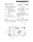
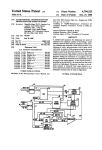
FIG. I is a perspective view showing the entire struc
(b4) a battery for providing the transmitting and re 55 ture of a cordless telephone in one of the embodiments
ceiving circuit with electric power, wherein
of the invention,
(c) the handset further comprises:
FIG. 2 is a block diagram showing a schematic elec
(cl) a device for display to indicate the in-service
trical structure of the cordless telephone in FIG. 1,
state,
FIG. 3 is a flow chart for explaining the operation of
(c2) a device for detecting the contact of the speaker 60 a base unit 23, and
area with a part ofthe body,
FIG. 4 is a flow chart for explaining the operation of
(c3) a device for detecting the talk to detect the in
a handset 1.
service state, and
DETAILED DESCRIPTION OF THE
(c4) a device for controlling to stop the display action
PREFERRED EMBODIMENT
of the display a device when the speaker area is in 65
contact with a part of the body and is in service, in
Referring now to the drawings, one of the preferred
response to the output from the contact detecting de
embodiments of the invention is described in details
vice and talk detecting device, and to effect the display
below.
3
5,010,566
4
ment of the invention. The cordless telephone 21 is
the detection signal is sent out to the control circuit 11.
The control circuit 11, on the basis of this detection
signal, sends out a stop signal to the driver 12. Thus,
connected to a telephone line 22, and include a handset
25 and a base unit 23 for radio communication there
with, the base unit 23 having an antenna 24 for radio
driving of the driver 12 is stopped, and the light emit
ting element 3 is extinguished at step n7. Afterwards,
when the user’s ear is departed again from the piezo
communication with the handset 25. The handset 25
includes key switches 2 such as numeric keys as a dial
electric element 7, the control circuit 11 then sends out
a drive signal to the driver 12 to drive the driver 12.
input device provided inside the grip of a handset unit 1;
This thereby lights the light emitting element 3 again.
Afterwards, by pressing the hang-up button 4 at step n3,
FIG. 1 is a perspective view showing the entire struc
ture of a cordless telephone 21 according to an embodi
a light emitting element 3 as a display device composed
of a light emitting diode (LED) or the like disposed in
the vicinity of the key switches 2 inside the grip; a dis
connect or hang-up button 4 as the talk completion
device for changing over between line capturing state
a communication circuit cut-off signal is sent out from
the handset 25 to the base unit 23 at step n4. Thus the
base unit 23 receives the communication circuit signal at
step m4 in FIG. 3. Then the connection with the tele
and talk waiting state; a transmitter 5 with a micro 15 phone line 22 is cut off at step m5, so that the light
phone 14 built in and located near the mouth of the user;
emitting element 3 of the handset 25 goes out.
a receiver 6 containing a piezoelectric element 7_ known
In this way, while the handset 25 is in service, the
as touch sensor or the like as the contact detecting
light emitting element 3 is being extinguished, and the
device when contacting with the ear, that is, a part of
consumption of the battery 28 can be considerably re
the body of the user contacted while talking; an antenna 20 duced.
8 for communicating with the base unit 23; and a battery
The invention may be embodied in other speci?c
28.
forms without departing from the spirit or essential
FIG. 2 is a block diagram showing a schematic elec
characteristics thereof. The present embodiments are
trical construction of the cordless telephone 21.
therefore to be considered in all respects as illustrative
In this diagram, a key signal by the operation of the 25 and
not restrictive, the scope of the invention being
key switch 2 is given to a control circuit 11 which is a
indicated
by the appended claims rather than by the
device for controlling the members in the handset 25. It
foregoing description and all changes which come
is also sent out from the antenna 8 through a transmit
within the meaning and the range of equivalency of the
ting and receiving circuit 13, and is received through
the antenna 24 of the base unit 23. It is then sent out to 30 claims are therefore intended to be embraced therein.
What is claimed is:
the telephone at the destination through the telephone
1. A cordless telephone apparatus including a base
line 22. Further, by the key signal from the key switch
unit
connected to a telephone line for communication,
2, the control circuit 11 sends out a drive signal to a
and a handset, operatively connected to the base unit by
Thus, the driver 12 is driven to light up the light emit 35 radio waves, including a speaker, a microphone, a trans
mitting and receiving circuit for communicating with
ting element 3. In the meantime, a signal from the piezo
the base unit by radio waves, transforming the signals
electric element 7 is applied to the control circuit 11,
from a caller into acoustic sound by the speaker, and
and a stop signal is sent out to the driver 12 from this
second the output from the microphone to the caller,
piezoelectric element 7. Thus, driving of the driver 12 is
and a battery for providing the transmitting and receiv
stopped to extinguish the light emitting element 3. At
ing circuit with electric power, the handset further
the same time, the control circuit 11 sends out a control
comprising:
signal to the transmitting and receiving circuit 13. The
driver 12 for lighting up the light emitting element 3.
transmitting and receiving circuit 13 ampli?es and mod
ulates the transmission signal received from a micro
phone 14 built in the transmitter 5. It then sends out a 45
signal from the antenna 8, and demodulates and ampli
?es the reception signal sent from the base unit 23
through the telephone line 22 which is a communication
circuit. Finally, it sends out a signal to a speaker 15 built
in the receiver 6. Thus, an acoustic signal is delivered 50
from the speaker 15. Such a handset 25 is electrically
powered by a built-in battery 28.
Referring now to FIG. 3 and FIG. 4, the talking
action of the base unit 23 and handset 25 will be de
scribed below. First, at step ml in FIG. 3, the talking 55
action is started. The handset 25 is unhooked from the
base unit 23 by the caller at step m2. Unhooking is
detected by the handset unhook detecting switch 27.
At step n1 in FIG. 4, when the key switch 2 is oper
ated and the telephone circuit 22 is connected at step n2,
a drive signal is issued from the control circuit 11 to the
driver 12. Further, when the talk button 4 is not pressed
at step n3, the operation goes to step n5. Then when the
line is busy, the operation advances to step n6. When
display means for indicating an in-service state of the
cordless telephone activated for communication;
contact detecting means for detecting contact of a
user with an area proximate to the speaker;
activation detecting means for detecting activation of
the cordless telephone for communications to de
tect the in-service state; and
control means operatively connected to the display
means, the contact detecting means and the activa
tion detecting means, for controlling the display
means to stop indicating an in-service state when
an area proximate to the speaker is detected to be in
contact with a user and an in service state is de
tected, in response to the contact detecting means
and activation detecting means, and for controlling
the display means to indicate an in-service state
when an area proximate to the speaker is not de
tected to be in contact with a user and an in service
state is detected; and
the handset battery means for electrically powering
the handset.
2. The cordless telephone apparatus of claim 1,
the receiver 6 is not in contact with the user’s ear, the 65 wherein the display means is a light emitting diode.
light emitting element 3 lights up at step n8. In this state,
3. The cordless telephone apparatus of claim 1,
when the user touches the receiver 6 of the handset by
wherein the contact detecting means is a piezoelectric
the ear, it is detected by the piezoelectric element 7, and
element.
5,010,566
5
6
4. The cordless telephone apparatus of claim 1,
9. The handset of claim 7, wherein the detecting
, wherein the handset further comprises dial means for
means is a piezoelectric element and the piezoelectric
element is disposed in close proximity to the speaker.
dial input, and the control means generates a dial signal
in response to activation of the dial input means to initi
10. The handset of claim 7, wherein the display means
is a light emitting diode (LED).
ateorcallviathebaseunit.
5. The cordless telephone apparatus of claim 1,
11. The handset of claim 7, wherein the handset is of
a “C" shaped con?guration, the speaker of the handset
being in one extended portion of the “C” and the trans
mitter being in the other extended portion of the “C”
wherein the contact detecting means includes a penetra- ~
tion hole in an area proximate to the speaker, the
speaker being disposed behind the contact detecting
such that a user’s ear and mouth can be simultaneously
means.
contacted to each of the respective extended portions of
'
the “C” shaped con?guration.
6. A cordless telephone apparatus including a base
12. The handset of claim 11, wherein the detecting
means is a piezoelectric element disposed in close prox
unit connected to a telephone line and a handset opera
tively connected to the base unit via radio communica
tion and equipped with a display device for indicating
an in-service state of the handset, the handset compris
mg:
contact detecting means for detecting contact when a
imity to the speaker.
13. The handset of claim 12, wherein the piezoelectric
element detects contact of the user's ear to the handset,
proximate to the speaker, and outputs a signal.
14. The handset of claim 7, further comprising:
part of the body of the user contacts with an area 20
end of service means, operatively connected to said
proximate to a speaker of the handset, and
control means, for outputting a signal to the con
stopping means for stopping the display device from
trol means to indicate that the cordless telephone is
not in-service, and wherein said control means,
indicating the in-service state when a part of the
upon receipt of said output signal from said end of
body of the user is detected to be in contact with an
service means, controls said display means to stop
area proximate to the speaker of the handset, in 25
displaying indication of the cordless telephone
response to the contact detecting means.
being in service.
7. Ahandset of a cordless telephone including a base
15. The handset of claim 7, further comprising:
unit and the handset including a speaker and a transmit
battery means, operatively connected to said display
ter for communicating, by radio communications, with
means for providing power to enable said display
the base unit, the handset further comprising:
means to display in-service indication.
display means for displaying indication of the cord
16. A method of conserving power of a battery in a
less telephone being in-service;
cordless telephone, including a handset with a battery, a
speaker and a receiver and further including a base unit,
contact of a user to an area of the handset in close 35 which indicates to a user when the cordless telephone is
detecting means for emitting a signal upon detecting
in-service, comprising the steps of:
proximity to the speaker; and
control means, operatively connected to said display
means and said detecting means, for controlling
said display means to display indication of the
cordless telephone being in-service upon not re
ceiving an output signal from said detecting means
when the cordless telephone is in service and for
(a) displaying indication, on the handset, of the cord
less telephone in-service;
(b) supplying power from the battery during said step
(a) of displaying;
(c) detecting contact of a user to an area of the hand
set in close proximity to the speaker;
(d) inhibiting said step (a) of displaying by stopping
controlling said display means to stop displaying
indication of the cordless telephone being in-ser 45
vice upon receiving an output signal from the de
tecting means when the cordless telephone is in
service.
8. The handset of claim 7 further comprising:
in-service detection means, operatively connected to
said control means, for outputting a signal to said
control means, upon detecting that the cordless
said step (b) of supplying power upon detecting
contact in step (c) to thus conserve battery power
while said telephone is in-service.
17. The method of claim 16, further comprising the
step of:
(e) terminating said step (a) of displaying upon said
telephone not being in-service.
18. The method of claim 16, wherein said step (c) of
detecting contact detects contact of a user’s ear to an
area of the handset in close proximity to the speaker.
telephone is in-service.
O
55
'
l
i
i