1
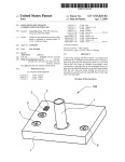
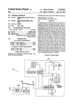
US007969496B2
(12) United States Patent
(10) Patent N0.:
(45) Date of Patent:
Pilu
(54)
(56)
CAMERA IMAGE STABILIZATION METHOD,
US 7,969,496 B2
Jun. 28, 2011
References Cited
APPARATUS AND COMPUTER PROGRAM
U.S. PATENT DOCUMENTS
(75) Inventor: Maurizi Pilu, Bristol (GB)
4,959,725
5,335,042
6,429,895
6,614,994
2002/0180876
(73) Assignee: Hewlett-Packard Development
Company, LP, Houston, TX (US)
(*)
Notice:
Subject to any disclaimer, the term of this
patent is extended or adjusted under 35
Dec. 25, 2003
Foreign Application Priority Data
Apr. 30, 2002
6/l998
IEEE Transactions on Consumer Electronics, v01. 35, N0. 4, Nov.
1989, pp. 749-758.
Tucker et al., “Image Stabilization for a Camera on a Moving Plat
form”, IEEE Pac Rim ’93, pp. 734-737.
Prior Publication Data
(30)
lO-l48859
Clarkson et al., “Unsupervised Clustering of Ambulatory Audio and
Video”, Perceptual Computing, MIT Media Lab.
Oshima et al., “VHS Camcorder With Electronic Image Stabilizer”,
Apr. 30, 2003
US 2003/0234885 A1
Mandle ....................... .. 358/222
Imafuji et a1. .
....... .. 396/55
Onuki .............. ..
348/208.99
Ohishi et al.
....... .. 396/55
Sobol .......................... .. 348/296
OTHER PUBLICATIONS
(21) Appl. N0.: 10/426,038
(65)
9/l990
8/1994
8/2002
9/2003
12/2002
FOREIGN PATENT DOCUMENTS
JP
U.S.C. 154(b) by 2515 days.
(22) Filed:
A
A *
Bl *
B2 *
Al*
* cited by examiner
Primary Examiner * Gevell Selby
(GB) ................................. .. 02099679
(57)
ABSTRACT
(51)
Int. Cl.
H04N 5/222
(52)
US. Cl. ............................ .. 348/333.02; 348/208.99
A camera comprises a user interface for the input of informa
tion indicative of the activity of a user. A control unit controls
at least one function of the camera in response to the infor
(58)
Field of Classi?cation Search ........... .. 348/333.02,
mation.
(2006.01)
348/208.99; 396/55
See application ?le for complete search history.
12 Claims, 4 Drawing Sheets
100
114
115
116
112
102
113
US. Patent
Jun.28,2011
Sheet10f4
US 7,969,496 B2
nMEDUE
E0
'% O
O!m:
o
US. Patent
Jun. 28, 2011
Sheet 2 0f4
131
US 7,969,496 B2
OPTICAL
\
IMAGE
&
M46
DETECTOR
ROM
11.1
‘| ,
Compensation
Programs
"'\
150
31
m ~I :42
M-
'
'28
40
113 “mg PROCESSOR EZZ> MEMORY
u: ___..____
m +=-133
115\-| ti
CARD
\4
I4 /—\
‘
v
IMAGE
42
Car
.434
IS
' A11“ =--I35
\lb \\
~1..___
1054'L'—
Ski
--136
Processor
ContrOIIeI;
/
13!
INTERNAL .444
SENSORS
Figure 2
US. Patent
Jun. 28, 2011
Sheet 3 of4
US 7,969,496 B2
No
200
Check whether
user interface
operated
l Yes
202
_
Determme type of
activity selected
204
Set camera motion compensation parameters based
upon selected activity
l
Capture image and/or image
206
.
.
.
sequence usmg motion compensation
FIGURE 3
US. Patent
Jun. 28, 2011
Sheet 4 0f 4
US 7,969,496 B2
US 7,969,496 B2
1
2
Preferably said information is utilised to determine what
CAMERA IMAGE STABILIZATION METHOD,
images will be captured and subsequently stored by the cam
APPARATUS AND COMPUTER PROGRAM
era.
Preferably, said information is indicative of at least one of
FIELD OF THE INVENTION
the type of motion likely to be undergone by the user; the type
of motion likely to be undergone by the camera; the attention
The present invention relates to methods, apparatus and
computer programs suitable for camera image stabilization.
of the user; the behaviour of the user; and the surrounding
environment.
Preferably, said camera further comprises a user activity
determination unit for estimating the activity of a user. The
camera utilizes the estimated activity if, for a predetermined
BACKGROUND TO THE INVENTION
A variety of digital and analogue cameras exist for captur
ing images in a number of formats including still picture
images, sequences of still picture images and video image
interval, said estimated activity differs from the activity indi
cated by the user input information.
Preferably, said camera is a wearable camera.
sequences.
In a further aspect, the present invention provides a user
interface for a camera. The user interface inputs information
The quality of an image is easily affected by movement of
the camera while the image is being collected, i.e., captured.
indicative of the activity of a user, for the subsequent control
Modern cameras, such as video cameras, now feature motion
of at least one function of the camera as a function of said
stabilization so as to produce a steady video image in spite of
any user handshake or other vibrational disturbances. This 20
improves the quality of the captured image.
For instance, US. Pat. No. 4,959,725 describes a method
of and apparatus for processing an image captured by a video
indicative of the activity of a user input from a user interface.
A further aspect of the invention relates to a camera com
camera so as to identify undesired video image motion caused
by camera motion (rotation or translation), and to subse
quently generate a corrected signal in which the undesired
information.
In another aspect, the present invention provides a camera
comprising a control unit arranged to control at least one
function of the camera in dependence upon information
25
prising a user interface for the input of information indicative
of at least one of the motion of the user and the motion of the
image motion is reduced.
camera. The camera includes a control unit arranged to con
It is known that different stabilization techniques are
needed to compensate for different types of motion. Modern
trol at least one function of the camera in dependence upon
cameras incorporate motion detection sensors to determine
the type of motion a camera experiences (e.g. sudden accel
eration or deceleration, or the camera slowly panning across
a view). The cameras apply the appropriate motion compen
sation technique automatically based on a derived measured
camera motion, and whether the motion is determined to be
30
At least one function of the camera is controlled as a function
35
deliberate or not.
Also known in the art are cameras that act as situation
based selective video recording systems. For instance, the
article “Unsupervised clustering of ambulatory audio and
video” by Brian Clarkson and Alex Pentland, Technical
said information.
In a further aspect, the present invention provides a method
of controlling a camera comprising the steps of: receiving
information from a user indicative of the activity of the user.
of the information.
Preferably the user activity is selected from a predeter
mined group of activities. Each activity in said group is asso
ciated with at least one predetermined parameter. The method
comprises the step of controlling said function by utilising
40
said parameter associated with the user selected activity.
In another aspect, the present invention provides a program
Report 471, MIT Media Lab, Perceptual Computing Group,
arranged to perform the above method.
describes a camera, including a wearable computer system,
arranged to record the day to day activities of a user. The
machine readable medium comprising the program.
In a further aspect, the present invention provides a
article describes the development of a system for extracting
events and scenes from the audio/visional input of the camera,
so that the camera images can easily be indexed.
Preferred embodiments of the present invention aim to
obviate or overcome a problem associated with the prior art,
45
BRIEF DESCRIPTION OF THE DRAWING
For a better understanding of the invention, and to show
how embodiments of the same may be carried into effect,
reference will now be made, by way of example, to the
whether referred to herein or otherwise.
50
SUMMARY OF THE INVENTION
accompanying diagrammatic drawings in which:
FIG. 1 is a perspective view of a camera according to a
preferred embodiment of the present invention;
In a ?rst aspect, the present invention provides a camera
comprising a user interface for the input of information
indicative of the activity of a user; and a control unit arranged
FIG. 2 is a block diagram of electronic circuitry in the
camera of FIG. 1;
55
to control at least one function of the camera in dependence
upon said information.
Preferably, said user interface comprises a user selection
unit for the manual selection of at least one activity from a
predetermined group of activities.
Preferably, said control unit is arranged to store said infor
FIG. 3 is a ?ow diagram of steps involved in operating the
camera of FIG. 1; and
FIG. 4 is a perspective view of a camera with a separate
user interface according to an alternative embodiment of the
present invention.
60
DETAILED DESCRIPTION OF THE DRAWING
mation with at least one image captured by the camera for
subsequent processing.
Preferably, said function comprises an image stabilisation
mode of the camera.
Preferably, said function comprises an image capture mode
of the camera.
65
FIG. 1 is a perspective view of a digital camera 100 that
comprises a user interface 102, lens 103, slot 104 for receiv
ing an image memory card, and shutter release button 105, as
well as a strap (not shown) suitable for attaching the camera
to a body part ofa user e.g. the user’s head.
US 7,969,496 B2
4
3
Processor 142 of the image stabilization unit (responsive to
The user interface 102 comprises six buttons 111-116.
Each of buttons 111-116 corresponds to a different potential
the image coupled through lens 103) provides image com
pensation for the image captured by detector 146 by utilizing
activity of the user i.e. socializing button 111, walking button
parametric dynamic models stored in programs 131-136 and
signals that control program 138 stores for determining which
112, running button 113, travelling on or in a motorized
vehicle such as an automotive vehicle button 114, riding a
image features and sensed movements of the camera are used
bicycle button 115 and skiing button 116. The user selects the
type of activity which he or she intends to undergo by pres sing
for stabilization, and to what degree. The activity setting
inputs of switches 111-116 by the user are associated with
entries in programs 131-136 that can be considered tables of
parameters that are used by the stabilization unit. The tables
ensure that processor 142 uses stabilization techniques and
the appropriate button.
Reference is now made to FIG. 2 of the drawing, a block
diagram of electronic circuitry included within camera 100.
The electronic circuitry includes switch contacts 121-126,
respectively associated with buttons 111-116, such that in
response to one of the buttons being pressed, the associated
parameters for the particular activity. Hence, different stabi
lizations are used for the different activities associated with
switches 111-116. Processor 142 supplies a signal indicative
switch contacts are closed. Each of switch contacts 121-126 is
of the stabilized image (via bus 148) to image memory card
connected to input terminals of read only memory (ROM)
130, which includes compensator programs 131-136, respec
tively associated with switch contacts 121-126. Compensator
150 of the type typically loaded in a digital camera.
For instance, wearable camera 100 mounted on a helmet
programs 131-136 are programs associated with social activi
ties, walking activities, running activities, riding in an auto
mobile activities, biking activities and skiing activities,
20
while skiing is stabilized by processor 142 in response to the
signals from programs 136 and 138, sensors 144 and detector
146. The stabilization is with respect to the ski track, and
ignores the skier head motion and trees in the signal that
respectively. ROM 130 also includes processor controller 138
detector 146 derives. Similarly, processor 142 in camera 100
and output bus 140 for supplying signals from compensator
mounted on a helmet of a person in a motor vehicle responds
programs 131-136 and process controller 138 to digital signal
processor 142. Programs 131-136 supply motion compensa
tion signals to processor 142 (typically an application speci?c
to switch 114, sensors 144 and detector 146 to ignore accel
25
eration-induced head motion and stabilize the motion only
integrated circuit (ASIC))via bus 140, under the control of
with respect to the car. When camera 100 is located on a
person in a social situation such as at a party, activation of
closure of switches 121-126 and processor controller 138,
which is activated to supply control signals to bus 140 and
processor 142 in response to shutter release button 105 being
button 111 causes program 131 to supply processor 142 with
a signal that takes into account the focus of interest of the user
(e.g. observing a fellow partygoer) so as to adequately record
30
pressed.
the desired still picture and/ or video sequence signal that
camera 100 supplies to memory card 150. It will be appreci
ated that these techniques relating to stabilization are pro
The motion compensation signals that programs 131-136
supply to processor 142 are derived in accordance with the
vided by way of example only, and that other stabilization
principals set forth in the previously mentioned Tucker and
Oshima et al. articles. Processor 142 is also responsive to
inertial sensors 144 included in camera 100 and the output of
optical image detector 146, included in camera 100 to be
35
activity input by the user.
The problem of image stabilisation has been known for a
responsive to the optical image coupled to the interior of the
camera via lens 103, as a result of the shutter (not shown) of
camera 100 being open in response to button 105 being
long time, and many algorithms and apparatuses have been
40
pressed. Processor 142 responds to the signals from the
selected compensator program 131-136, inertial sensors 144,
and optical image detector 146 to produce a digital compen
sated image representing signal under the control of process
controller 138. Processor 142 includes output bus 148 for
techniques can be utilized as appropriate depending on the
45
devised to address this problem. Prior art solutions have uti
lized automatic motion detection. However, automatic
motion detection is prone to errors, unpredictable behaviours
and requires extra processing power and/or hardware, to pro
vide adequate image compensation in a wide variety of situ
ations. By providing user interface 102 that employs manual
settings of user activity, the motion compensation that pro
supplying digital signals representing the compensated
cessor 142 provides can be optimized for the particular
image. Processor 142 supplies the compensated image rep
motion types likely to be experienced during that activity. The
image stabilization techniques can thus be inexpensively and
resenting signal to image memory card 150 via bus 148.
Image memory card 150 is of a conventional type adapted to
easily optimized, making best use of the available informa
Thus, buttons 111-116 are respectively associated with
compensation programs 131-136 of read only memory
tion that can be detected by the camera.
FIG. 3 is a ?ow diagram of the steps control program 138
causes processor 142 of camera 100 (having user interface
(ROM) 137, which can be considered part of an electronic
image stablization unit located in camera 100. ROM 130
button 105. Firstly, program 138 causes processor 142 to
be inserted into slot 104 of camera 100.
responds to activation of buttons 111-116 to supply (via bus
140) electronic processor 142 with signals from the program
50
102) to perform in response to operation of shutter release
55
131-136 selected by one of buttons 111-116 and from pro
gram 138.
Processor 142 is programmed by the signals on bus 140 to
process an image signal that detector 146 supplies to the
Once processor 142 determines that the user interface has
60
processor to compensate for the motion of camera 100. The
image stabilization unit including processor 142 also includes
inertial sensors 144 that measure movement of the camera
and acceleration experienced by the camera. Processor 142
combines the signals from sensors 144, detector 146 and on
bus 140 to form an image processing unit that determines key
features of the image captured by detector 146.
make a check, by reading the signal on bus 140 to determine
whether user interface 1 02 has been operated (operation 200).
65
been operated, program 138 activates processor 142 by read
ing bus 140 to determine the type of activity selected i.e.
which one of buttons 111-116 has been pressed (operation
202). Subsequently, based upon the determined type of activ
ity, the camera motion processor 142 responds to the signal on
bus 140 indicative of the compensation parameters appropri
ate for the activity as supplied to the processor 142 from the
selected program 131-136 of the camera image compensation
processing unit. These parameters, in combination with the
signals from inertial sensors 144 adjust the operation of pro
US 7,969,496 B2
5
6
cessor 142 in processing the image from detector 146 so as to
images (still pictures, sequences of pictures and/or video
be most appropriate for the selected activity (operation 204).
sequences) should be captured or indexed.
Subsequently the signal representing the captured image
Such a memory aid camera might have a user interface
and/or captured image sequences are motion compensated
(operation 206) using the selected parameters and then sup
plied by processor 142 to memory card 150 via bus 148.
Examples of motion compensation using different param
de?ning user activities such as “shopping”, “commuting”,
“working” and “at a party”. When the “party” activity is
selected, such a camera would be arranged to automatically
eters for different motions are described in the articles I. C.
Tucker, A. de San Lazaro, “Image stabilization for a camera
focus for a relatively long period of time. This is likely to
result in the capture and/or indexing of images of people
on a moving platform”, Proceedings of IEEE Paci?c Rim
Conference on Communications Computers and Signal Pro
cessing, Vol. 2, pp 734-7, May 1993, and in M. Oshima, et al.,
“VHS Camcorder with Electronic Image Stabilizer”, IEEE
whom the user would like to remember.
capture and/or index images on which the user appears to
Alternatively, if the user selects the “working” activity by
pressing an apparatus “work” button (not shown) on camera
100, program 138 responds to the pressed work button to
cause camera 100 to automatically capture and/or index
Transactions on Consumer Electronics, vol. 35, no 4, pp
749-758, June 1989. These articles describe how the camera
motion can be automatically detected, and then the motion
images only when the majority of the scene changes.
This ensures that images are not captured and/or indexed
when the user is sitting and continuously working at a desk.
compensation applied.
Because detecting motion automatically can be very unre
liable, the manual selection through user interface 102 (as
proposed above) puts the user in control of the behavior of
The camera also includes an internal clock that is part of
processor 142. In response to activation of the “wor ” button,
20
camera 100 responds to the clock to only capture images
camera 100. In cases such as when the user’s motion de?nes
during working hours, and not to capture images during other
the very model of user attention, this is even more important.
hours e.g. during the lunch interval.
While various examples of activities have been disclosed,
it will be appreciated that the term “activity” can be inter
preted as any occupation or pursuit being undergone by a user,
including the user undergoing various forms of motion and
the user undergoing various social and environmental inter
actions during which the user’s attention might be directed at
It will be appreciated that the above embodiment is pro
vided by way of example only, and that other embodiments
fall within the scope of the present invention.
25
For instance, the user interface 102 can be a unit separate
from the camera, and arranged to communicate with the
camera via an umbilical cord 104 (as shown in FIG. 4) or
wireless communication e.g. infrared communication
between the camera and the user interface unit.
While the user interface 102 has been indicated as com
different subjects.
30
The reader’s attention is directed to all papers and docu
ments which are ?led concurrently with or previous to this
prising a number of discrete manually operated buttons 111
speci?cation in connection with this application and which
116, it will be appreciated that a user interface can be imple
are open to public inspection with this speci?cation, and the
mented with any HCI (Human Computer Interaction)
contents of all such papers and documents are incorporated
mechanism, such as a graphical user interface, soft buttons, or
speech recognition. Such an interface can be pre-pro
grammed with a pre-de?ned set of activities linked to a pre
de?ned set of parameters for control of the camera, or any
aspect can be controlled and programmed by the user. For
35
instance, the user might alter the parameters associated with
the “bike” button 115 so as to provide optimum compensation
for the type of bike riding normally undertaken by the user,
40
of the steps of any method or process so disclosed, can be
such as whether the user normally rides on the road or
45
image stabilisation unit to provide motion compensation/
image stabilisation for the captured image, the present inven
tion can also be applied to cameras which do not have such on
board units. Instead, information indicative of the selected
activity can be stored along with the image data. Such infor
mation can subsequently be utilised for optimum processing
of the image data in a post-capture phase. For instance, a
video sequence might be stabilised after capture on another
viewing apparatus (e.g. use of a personal computer) accord
ing to an activity setting input by the user aron the time the
50
instance, a camera arranged to be worn by the user and act as
a memory aid, could use the information to determine which
features.
The invention is not restricted to the details of the foregoing
embodiment(s). The invention extends to any novel one, or
any novel combination, of the features disclosed in this speci
drawings), or to any novel one, or any novel combination, of
the steps of any method or process so disclosed.
55
The invention claimed is:
1. A camera, comprising:
a user interface for the input of information indicative of
the activity of a user wherein said user interface com
60
prises a user selection unit for the manual selection of at
least one activity from a predetermined group of manu
ally selectable activities;
attention of the user or the environment surrounding the user,
or to otherwise set the context in which the camera is expected
to operate. Such information can be utilised by the camera to
control other functions besides image stabilisation. For
or similar purpose, unless expressly stated otherwise. Thus,
unless expressly stated otherwise, each feature disclosed is
one example only of a generic series of equivalent or similar
?cation (including any accompanying claims, abstract and
image was captured.
In the preferred embodiment, user interface 102 is utilised
to input information indicative of the activity of the user, and
hence the type of motion of the user. Equally however, a user
interface could be utilised to input information on the activity
of the user indicative of the behaviour of the user, the likely
combined in any combination, except combinations where at
least some of such features and/or steps are mutually exclu
sive.
Each feature disclosed in this speci?cation (including any
accompanying claims, abstract and drawings), can be
replaced by alternative features serving the same, equivalent
engages in mountain biking.
While the preferred embodiment utilises an in-camera
herein by reference.
All the features disclosed in this speci?cation (including
any accompanying claims, abstract and drawings), and/or all
a control unit arranged to control at least one function of the
65
camera in dependence upon said information; and
a user activity determination unit arranged to estimate the
activity of a user, the camera being arranged to utilize the
estimated activity if, for a predetermined interval, said
US 7,969,496 B2
8
7
estimated activity differs from the manually selected
a control unit arranged to control at least one function of the
activity indicated by the input information.
camera in dependence upon said information; and
a user activity determination unit arranged to estimate the
activity of a user, the camera being arranged to utilize the
2. The camera as claimed in claim 1, Wherein said control
unit is arranged to store said information With at least one
image captured by the camera for subsequent processing of
said image.
activity indicated by the input information.
3. The camera as claimed in claim 1, Wherein said function
comprises an image stabilization mode of the camera.
4. The camera as claimed in claim 1, Wherein said function
comprises an image capture mode of the camera.
5. The camera as claimed in claim 4, Wherein said infor
mation is utilized to determine What images are captured and
10. A method of controlling a camera comprising the steps
of:
causing a user of the camera to manually supply informa
tion to the camera indicative of a manual selection of
manually selectable mode of activity of the user;
controlling at least one function of the camera as a function
subsequently stored by the camera.
6. The camera as claimed in claim 1, Wherein said infor
mation is indicative of at least one of the type of motion likely
of said information;
15
is a wearable camera.
8. A camera comprising:
a control unit arranged to control at least one function of the
camera in dependence upon information indicative of a
manual selection of an activity from among a plurality of
manually selectable activities by user manual input from
mation.
20
25
the step of controlling said function of the camera by utilizing
a parameter associated With the selected activity.
12. A non-transitory storage medium storing a computer
program arranged to control a camera, the program being
arranged to cause the camera to:
receive information manually input from a user indicative
of a selection of an activity from a plurality of selectable
estimated activity if, for a predetermined interval, said
estimated activity differs from the activity indicated by
the input information.
activities by the user;
control at least one function of the camera in dependence
upon said information;
9. A camera comprising:
a user interface for the manual selection of an activity from
a selection of selectable activities and associated input of
11. The method as claimed in claim 10, Wherein each one
of the activities in said group being associated With at least
one predetermined parameter, the method further comprising
a user interface; and,
a user activity determination unit arranged to estimate the
activity of a user, the camera being arranged to utilize the
information indicative of at least one of a manually
selectable motion of the user and a manually selectable
motion of the camera;
estimating the activity of a user; and
utilizing the estimated activity if, for a predetermined inter
val, said estimated activity differs from the manually
selected mode of activity indicated by the supplied infor
to be undergone by the user; the type of motion likely to be
undergone by the camera; the attention of the user; the behav
ior of the user; and the surrounding environment.
7. The camera as claimed in claim 1, Wherein said camera
estimated activity if, for a predetermined interval, said
estimated activity differs from the manually selectable
5
estimate the activity of a user; and
35
utilize the estimated activity if, for a predetermined inter
val, said estimated activity differs from the activity indi
cated by the supplied information.
*
*
*
*
*
UNITED STATES PATENT AND TRADEMARK OFFICE
CERTIFICATE OF CORRECTION
PATENT No.
: 7,969,496 B2
APPLICATION No.
DATED
: 10/42603 8
; June 28, 2011
INVENTOR(S)
: Maurizio Pilu
Page 1 of 1
It is certified that error appears in the above-identi?ed patent and that said Letters Patent is hereby corrected as shown below:
On the Title page, in ?eld (75), Inventor, in column 1, line I, delete
“Maurizi Pilu,” and insert -- Maurizio Pilu, --, therefor.
Signed and Sealed this
Third Day of April, 2012
David J. Kappos
Director 0fthe United States Patent and Trademark O?ice


![`95385109 1%]?](http://vs1.manualzilla.com/store/data/005699459_1-7fc02fda0f8970d7c2f678aea00486d8-150x150.png)