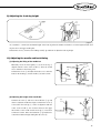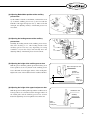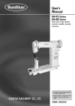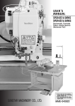
1
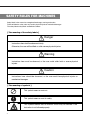
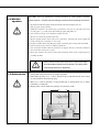
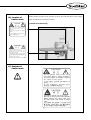
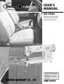
R
USER’S
MANUAL
KM-590BL
Single-needle, unison feed
lock stitch sewing machine
(with vertical large hook)
SUNSTAR MACHINERY CO., LTD.
1) For proper and trouble-free use of the
machine, thoroughly read this manual
before use.
2) Keep this manual in a safe place for
future reference in case the machine
breaks down.
MME-050509
lity
a
u
tQ
Besst Pricevice
Be st Ser
Be
1. Thank you for purchasing our product. Based on the rich expertise and
experience accumulated in industrial sewing machine production, SUNSTAR
will manufacture industrial sewing machines, which deliver more diverse
functions, high performance, powerful operation, enhanced durability, and
more sophisticated design to meet a number of user’s needs.
2. Please read this user’s manual thoroughly before using the machine. Make
sure to properly use the machine to enjoy its full performance.
3. The specifications of the machine are subject to change, aimed to enhance
product performance, without prior notice.
4. This product is designed, manufactured, and sold as an industrial sewing
machine. It should not be used for other than industrial purpose.
R
SUNSTAR MACHINERY CO., LTD.
Table of contents
SAFETY RULES FOR MACHINES ...................................................................................................................... 4
1. SPECIFICATIONS .................................................................................................................................................. 8
1) Specifications of KM-590BL .................................................................................................................................... 8
2) Application ................................................................................................................................................................. 8
2. INSTALLATION ...................................................................................................................................................... 9
1) Installation of the oil fan ............................................................................................................................................ 9
2) Installation of head enclosures ................................................................................................................................ 10
3) Lubrication ............................................................................................................................................................... 10
4) Adjustment of belt tension ....................................................................................................................................... 11
5) Installation of the knee-lifting device ...................................................................................................................... 11
3. ADJUSTMENT OF THE MACHINE ............................................................................................................ 12
1) Placing the needle .................................................................................................................................................... 12
2) Winding the lower thread ........................................................................................................................................ 12
3) Inserting the bobbin ................................................................................................................................................. 12
4) Routing the upper thread ......................................................................................................................................... 13
5) Adjusting the thread tension .................................................................................................................................... 13
6) Adjusting the spring tension .................................................................................................................................... 14
7) Adjusting the number of stitches ............................................................................................................................. 14
8) Adjusting the presser foot pressure ......................................................................................................................... 14
9) Adjusting the feed dog height .................................................................................................................................. 15
10) Adjusting the needle and hook timing .................................................................................................................. 15
11) Adjusting the auxiliary presser foot and upper feed presser foot ......................................................................... 16
SAFETY RULES FOR MACHINES
Safety labels in the manual are categorized into danger, warning and caution.
Failure to follow the safety rules may result in physical injuries or mechanical damages.
The safety labels and symbols are defined as follows.
[ The meaning of the safety labels ]
Danger
Instructions here shall be observed strictly.
Otherwise, the user will be killed or suffer severe physical injuries.
Warning
Instructions here must be observed, or the user could suffer fatal or severe physical
injuries.
Caution
Instructions here should be observed, or the user could face physical injuries or
mechanical damages.
[ The meaning of symbols ]
This symbol means a must-not.
This symbol means a must for safety.
This symbol means that an electric shock may be caused if the
instruction is not followed properly.
4
1-1) Machine
mobilization
Only personnel with a full understanding of the safety rules should move the
machines. The following directions must be observed when delivering the machines.
ⓐ At least two or more people should move the machine.
ⓑ Before delivering the machine, thoroughly wipe off the oil on the machine to prevent
accidents.
Danger
1-2) Machine
installation
Caution
Physical damages such as functional difficulties or breakdowns may occur
depending on installation conditions of the machines. Be sure to heed the following
conditions.
ⓐ Remove the packing from top to bottom. Watch out for nails on the wooden box.
ⓑ Install an air conditioner and clean it regularly to prevent dust and moisture build-up
from contaminating and corroding the machines.
ⓒ Keep the machines away from direct sunlight.
ⓓ Keep a minimum distance of 50cm between the machine at both sides and backside
and the wall to secure sufficient space for repair
ⓔ Risk of explosion
Do not operate the machine near areas with danger of explosion. Refrain from
running the machine in the vicinity of risky places e.g., where a large quantity of
aerosol-spraying products or oxygen are handled, unless specific guarantees are given
otherwise for the operation of the machine to prevent explosion at such places.
ⓕ The user should install an illuminator in the work area for the machine does not come
supplied with any lighting apparatus due to the specific features of the machine.
[Note] Details of the machine installation are laid out in No. 2 INSTALLATION.
1-3) Troubleshooting
Danger
When the machine is in need of repair, only our authorized service technicians must
handle it.
ⓐ Before cleaning and repairing the machine, shut off the power supply and wait four
minutes for the machine to discharge completely.
ⓑ No part of the machine or specifications may be modified without prior consultation with
our company. Any such modification could risk safe operation of the machine.
ⓒ In case of repair, replace only with standard OEM parts from SunStar.
ⓓ After repair, put safety covers back on the machine.
5
1-4) Machine
operation
Caution
KM-590BL series are intended for industrial purposes for sewing textiles and other
similar materials. Carefully study the following instructions before operating the machine.
ⓐ Read the manual thoroughly and understand the instructions fully before use.
ⓑ Put on proper safety garments.
ⓒ While the machine is in motion, keep your hands or any part of your body away from
moving parts, e.g., needle, hook, thread take-up spring and pulley, etc.
ⓓ Do not remove safety covers while the machine is in use.
ⓔ Be sure to connect the ground (earth) wire.
ⓕ Before opening electric boxes such as the control box, shut down the power supply and
make sure the power switch is in“off”mode.
ⓖ Stop the machine before threading the needle or checking after sewing work is finished.
ⓗ Never turn the power switch on with the pedal down.
ⓘ Do not run the machine when the cooling fan is clogged. Be sure to clean the air filter in
the control box at least once a week.
ⓙ Keep the machine away from strong electromagnetic fields such as high frequency
welding machines.
Caution
1-5) Safety device
Caution
Always start the machine with safety covers in place since fingers
or hands could be injured or cut off by the belt. Turn off the power
switch during check-ups or adjustments.
ⓐ Safety label: Safety instructions for machine operations
ⓑ Thread take-up spring cover: A device designed to prevent the human body from coming
in contact with the thread take-up spring
ⓒ Belt cover: A device intended to avoid potential risks of getting hands, feet or clothes
jammed by a rotating belt
ⓓ Finger guard: A device built to keep fingers away from the needle.
ⓑ
ⓐ
ⓒ
ⓓ
6
1-6) Location of
Caution mark
CAUTION
경 고
Caution mark is attached on the machine for safety. Read the directions of the Caution
mark carefully before running the machine.
[Location of caution mark]
Do not operate without finger guard and
safety devices. Before threading, changing
bobbin and needle, cleaning etc. switch off
main switch.
손가락 보호대와 안전장치 없이 작동하지
마십시오.
실, 보빈, 바늘교환시나 청소전에는 반드시 주
전원의 스위치를 꺼 주십시오.
CAUTION
경 고
Hazardous voltage will cause injury.
Be sure to wait at least 360 seconds before
opening this cover after turn off main switch
and unplug a power cord.
고압 전류에 의해 감전될 수 있으므로 커버를
열 때는 전원을 내리고 전원 플러그를 뽑고 나
서 360초간 기다린 후 여십시오.
1-7) Contents of
Caution mark
Caution
CAUTION
경 고
Do not operate without finger guard
and safety devices. Before threading,
changing bobbin and needle, cleaning
etc. switch off main switch.
손가락 보호대와 안전장치 없이 작동하지 마
십시오.
실, 보빈, 바늘교환시나 청소전에는 반드시
주전원의 스위치를 꺼 주십시오.
CAUTION
경 고
Hazardous voltage will cause injury.
Be sure to wait at least 360 seconds
before opening this cover after turn
off main switch and unplug a power
cord.
고압 전류에 의해 감전될 수 있으므로 커버
를 열 때는 전원을 내리고 전원 플러그를 뽑
고 나서 360초간 기다린 후 여십시오.
7
1
SPECIFICATIONS
1) Specifications of KM-590BL
DESCRIPTION
SPECIFICATION
Application
For very heavy materials
Max. sewing speed
2,000SPM
Max. No. of stitches
9mm
Needle bar stroke
35mm
Manual
9mm
Knee lifting
16mm
Presser foot height
Needle used
DP×17 (#20~#25), standard needle #23
Feed dog height
1~1.2mm
Hook used
Vertical full-rotating double hook (very heavy materials)
Lifting amount of main/auxiliary presser foot
2~5.5mm
Lubrication
Manual/ drop oiling tank
Bed size
475mm×178mm
2) Application
For container bags, car seats, large bags (suitcases, etc.), raincoats, or sewing materials with large thickness differences.
8
2
INSTALLATION
Warning
▶ The machine must be installed by a trained technician only.
▶ Any electrical wiring must be performed by a qualified technician or agent.
▶ The machine weighs over 35 kg. As such, two or more people should carry out the installation.
▶ Plug in only after the installation is complete. If the operator mistakenly steps down on the pedal
with the plug in, the machine will start automatically and can cause physical injuries.
▶ Connect the ground (earth) wire. An unstable connection may result in an electric shock or a
malfunction.
▶ Place the belt cover on top of the machine
▶ Use both hands when bending the machine backward or returning it to the normal position.
Using only one hand can lead to severe hand injuries due to the weight of the machine.
1) Installation of the oil fan
④
Fix the oil fan ① onto the table with six screws ②. Use screws
④ to mount the head support rubbers ③ onto four corners of the
table. Insert the oil drain ⑤ into the oil fan ①.
③
30
25
①
⑤
②
[ Figure 1 ]
9
2) Installation of head enclosures
③
②
①
[ Figure 2 ]
Insert the head hinge ① into the bed hole and align it well with the head hinge rubber ② of the table. Place the machine on
the head support rubber ③.
3) Lubrication
Before using the machine, be sure to supply a sufficient amount
of oil through the lubrication hole marked with red color. Pour
oil into the arm lubrication tank ① and bed lubrication tank ②
to the red line. Check lubrication once a day.
①
[ Figure 3 ]
Oil supply adjustment of the hook
Use the screw ③ on the right side of the bed lubrication tank ②
to adjust the amount of oil supply. Turn the screw ③ to the right
(+) to increase the oil supply, and to the left (-) to decrease the
oil supply.
②
Oil tank
③
[ Figure 4 ]
10
4) Adjustment of belt tension
The machine rotates to the left when seen from the pulley.
To get a proper level of belt tension, turn the nut ② to an
extent at which the belt ① can be bent by 15~20mm when
pressed by hand.
①
15~20mm
[ Caution ]
Be sure to lift the presser foot when racing the machine.
②
[ Figure 5 ]
5) Installation of the knee-lifting device
Fix the knee-lifting device (ass’y) ① under the table ② with
four screws ③.
②
215
③
①
[ Figure 6 ]
11
3
ADJUSTMENT OF THE MACHINE
1) Placing the needle
Insert the needle ① deeply into the hole ② of the needle bar,
with the long groove of the needle facing left. Then, tighten the
screw ③ to hold the needle.
②
③
①
[ Figure 7 ]
2) Winding the lower thread
(1) Place the bobbin ① into the bobbin winder shaft ②.
(2) Press the bobbin winder lever ③
(3) Manually wind the thread on the bobbin ① a few times in
the winding direction and start the machine.
(4) If the thread does not wind in parallel, unfasten the fixing
screw ④ of the thread guide and move the thread guide plate
⑤ to the left and right to ensure the right adjustment.
(5) Loosen the adjusting screw ⑥ if there is too much thread on
the bobbin ①, or tighten it if there is too little.
⑤
④
②
①
⑥
③
80%
[ Figure 8 ]
3) Inserting the bobbin
(1) Insert the bobbin into the bobbin case along the arrow
direction as illustrated in the Figure. Be sure to place the
bobbin in the right direction to prevent loose threads and the
lower thread from getting wound.
(2) Through the thread guide ①, drop the thread down the
spring ② of the lower thread tension-adjusting plate and pull
it out from the thread hole ③.
①
②
②
③
[ Figure 9 ]
12
4) Routing the upper thread
②
③
④
⑧
①
⑦
⑨
⑦
⑨
⑤
⑥
⑩
⑤
⑥
⑪
⑫
[ Figure 10 ]
Set the thread take-up lever at the highest position.
Pass the thread from the left to the right of the needle.
Caution
▶ Turn the power switch off when adjusting the lower thread tension. If the user mistakenly presses
down on the foothold, the machine will start automatically and can cause physical injuries.
▶ When the clutch motor is used, be aware that it will continue to rotate due to inertia even after the
power switch is turned off. Be sure to work on the machine only after the motor comes to a
complete stop.
5) Adjusting the thread tension
①
Weak
Strong
②
[ Figure 11 ]
Turn the screw ① to adjust tension of the lower thread. Set the tension loosely so that when the end of the lower thread is
lifted manually, the thread does not start to unravel due to the weight of the bobbin case.
※ Tension at which the thread comes off from the bobbin case is normally 30~50g.
For adjustment of the upper thread, push down the presser foot and turn the tension control screw ②.
13
7~
10
m
m
6) Adjusting the spring tension
④
Strong
40~60g
Large
Small
Weak
③
[ Figure 12 ]
The thread take-up stroke is normally 7~10mm. As a standard, the twisting strength of the thread take-up spring is 40~60 g.
Loosen the screw ③ of the thread take-up lever and turn the thread-adjusting device to achieve the proper thread take-up
stroke. (Set the stroke low for heavy materials and high for light materials)
Insert the driver into the groove of the post ④ of the thread-adjusting device. Turn it left and right to adjust the tension of
the thread take-up spring. (High for heavy materials and low for light materials)
7) Adjusting the number of stitches
Align the number indicated on the dial ① with a pin ②
placed above the dial.
※ The higher the number is, the more number of stitches
you will get.
②
Press in the reverse lever ③ to perform reverse sewing, and
take your hand off the lever to perform normal sewing.
①
③
[ Figure 13 ]
8) Adjusting the presser foot pressure
Loosen the fixing nut ② of the pressure-adjusting screw.
Rotate the pressure-adjusting screw ① to the left and right to
set the pressure low, just enough to keep the sewing material
in place. Tighten back the fixing nut ②.
Unfasten the fixing nut ② of the pressure-adjusting screw.
Turn the pressure-adjusting screw ① in a clockwise direction
to increase the pressure, and turn in a counterclockwise
direction to decrease the pressure. Tighten the fixing nut ②
after adjustments.
Strong
②
①
Weak
[ Figure 14 ]
14
9) Adjusting the feed dog height
②
1~1.2mm
①
[ Figure 15 ]
As a standard, 1~1.2mm is the maximum height of the feed dog when the number of stitches is set at the highest and the feed
dog rises above the upper needle plate.
Unfasten the screw ① and move the holding crank ② up and down to adjust the feed dog height.
10) Adjusting the needle and hook timing
(1) Adjusting the lifting of the needle bar
Manually rotate the hand pulley to set the hook tip ①
aligned with the center of the needle ②, when the needle
rises 2.3mm above the lowest point.
Unfasten the screw ③ and adjust the hook to set a clearance
between the hook tip ① and the needle ② at 0.05~0.1mm.
②
①
0.05~0.1mm
③
①
②
2.3mm
[ Figure 16 ]
(2) Adjusting the height of the needle bar
Unfasten the screw ④ and move the needle bar ⑤ up and
down to adjust the needle bar height. Unfasten the screw ④
so that when the hook tip ① comes in alignment with the
center of the needle ②, the clearance between the upper
thread hole of the needle and the hook tip ① is between
0.5mm and 1.5mm. Move the needle bar ⑤ up and down to
control the needle bar height and tighten the screw ④.
④
②
⑤
0.5~1.5mm
①
[ Figure 17 ]
15
Caution
▶ Be sure to place back safety devices and check whether they function properly, after
disassembling and adjustments.
▶ Use both hands when bending the machine backwards or returning it to the normal position.
Using only one hand can lead to physical injuries due to the weight of the machine.
▶ Be sure to pay caution to safety when making adjustments with the power switch on.
▶ The machine must be repaired and inspected only by trained technicians.
▶ Qualified technicians or agent must perform electrical repairs or inspections.
11) Adjusting the auxiliary presser foot and upper feed presser foot
(1) Adjusting the crossing amount of the presser foot
The auxiliary presser foot ① and the upper feed presser
foot ② move up and down by turns.
When the auxiliary presser foot ① and the upper feed
presser foot ② come to their highest positions, either set
them at the same height or lower the height of the upper
feed presser foot ① by a small degree. For adjustments,
bring the thread take-up lever to the lowest position, push
down the presser bar lifter ③, unfasten the crank-fixing
screw ④ and move the adjusting crank ⑤ left and right.
(When moved to the left, the lifting amount of the upper
feed presser foot will become smaller.)
①
④
⑤
②
Left
Right
③
Same height
[ Figure 18 ]
(2) Adjusting Up/Down movement of the auxiliary and upper feed presser foot
⑥
2.5mm
①
②
⑦
[ Figure 19 ]
The auxiliary presser foot ① and the upper feed presser foot ② are set to move 2~5.5mm vertically. For adjustment, unfasten
the nut ⑥ to a degree suitable for sewing materials and vertically move the Up/Down-adjusting shaft ⑦ of the presser foot.
※ For sewing materials with small thickness difference, set the Up/Down movement at a minimum.
(Highest: 5.5mm, Lowest: 2mm)
16
(3) Adjusting Before/After position of the auxiliary
presser foot
Set the number of stitch at a maximum. Unfasten the screw
⑨ so that the auxiliary presser foot ① does not touch the
backside of the upper feed presser foot ②. Move to the left
and right, the adjusting crank ⑩ of horizontal presser foot
movement.
①
②
⑩
⑨
①
②
Allowance
[ Figure 20 ]
(4) Adjusting the feeding amount of the auxiliary
presser foot
Normally, the feeding amount of the auxiliary presser foot to
that of the feed dog is 1:1. The feeding amount of the
auxiliary presser foot may vary depending on sewing
conditions. Loosen the nut ⑪ and vertically move the
adjusting shaft ⑫ of horizontal presser foot movement.
⑪
Small
Large
⑫
③
[ Figure 21 ]
(5) Adjusting the height of the auxiliary presser foot
With the presser bar lifter pushed up and the feed dog at its
lowest position, set the very bottom of the auxiliary presser
foot to lift 8mm off of the upper surface of the needle plate.
Tighten the screw of the needle bar in the needle bar bracket.
Upper feed presser foot
Auxiliary
presser foot
Upper
surface of
needle plate
8mm
[ Figure 22 ]
(6) Adjusting the height of the upper feed presser foot
With the presser bar lifter pushed up and the needle bar at its
lowest position, set a clearance between the upper surface of
the needle plate and the auxiliary presser foot at 5mm.
Fasten the tightening screw for Up/Down movement cam.
Needle bar low
Auxiliary
presser foot
Upper
surface of
needle plate
5mm
[ Figure 23 ]
17
(7) Setting the position of Up/Down movement cam
With the dial set at zero and the needle bar lifter pushed up,
manually rotate the pulley to bring the needle bar to its
highest position. At this point, place the no. 2 screw of
Up/Down movement cam at the 12 o’clock position and
tighten the screw afterwards.
No. 2 screw
No. 1 screw
Upper
shaft
Up/Down movement cam
[ Figure 24 ]
18
MEMO
MEMO
MEMO
MEMO
MEMO