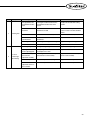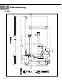
1
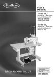
User’s
Manual
KM-957 Series
Post bed with driven roller foot,
one-needle, drop-feed back tack
sewing machine
KM-967 Series
Post bed with driven roller foot,
two-needle, drop-feed back tack
sewing machine
1. For proper use of the machine, read
thoroughly this manual before use.
SUNSTAR MACHINERY CO., LTD.
2. Keep this manual in a safe place for future
reference in case the machine breaks
down.
MME-050629
lity
a
u
tQ
Besst Pricevice
Be st Ser
Be
1. Thank you for purchasing our product. Based on the rich expertise and
experience accumulated in industrial sewing machine production, SUNSTAR
will manufacture industrial sewing machines, which deliver more diverse
functions, high performance, powerful operation, enhanced durability, and
more sophisticated design to meet a number of user’s needs.
2. Please read this user’s manual thoroughly before using the machine. Make
sure to properly use the machine to enjoy its full performance.
3. The specifications of the machine are subject to change, aimed to enhance
product performance, without prior notice.
4. This product is designed, manufactured, and sold as an industrial sewing
machine. It should not be used for other than industrial purpose.
R
SUNSTAR MACHINERY CO., LTD.
Table of Contents
Safety rules for machines ..................................................................................................................................... 4
1. Specification ........................................................................................................................................................... 8
1) Sewing machine ......................................................................................................................................................... 8
2) Servo motor .................................................................................................................................................................8
3) 470 motor ................................................................................................................................................................... 8
4) 470 motor controller ................................................................................................................................................... 8
5) Clutch motor ............................................................................................................................................................... 9
6) Peripheral automation devices (optional) .................................................................................................................. 9
2. Installation .............................................................................................................................................................. 10
1) Installation of machine head .................................................................................................................................... 10
2) Installation of oil tray (oil fan) ................................................................................................................................. 10
3) Installation of automatic knee lifting solenoid and power switch box ................................................................... 11
4) Lubrication ............................................................................................................................................................... 11
5) Adjustment of belt tension ....................................................................................................................................... 12
6) Installation of program unit (for automatic trimming type) ................................................................................... 12
7) Installation of belt cover .......................................................................................................................................... 12
8) Installation and adjustment of synchronizer (for automatic trimming type) ......................................................... 13
9) Description of back tack button (for automatic trimming type) ............................................................................. 14
10) Check for machine stop position (for automatic trimming type) ......................................................................... 14
3. Machine Adjustment
1) Inserting needle ........................................................................................................................................................ 15
2) Removing bobbin and bobbin case ......................................................................................................................... 15
3) Inserting lower thread .............................................................................................................................................. 16
4) Inserting bobbin ....................................................................................................................................................... 16
5) Routing upper thread ................................................................................................................................................ 16
6) Adjusting thread tension .......................................................................................................................................... 17
7) Adjusting roller presser foot height and pressure ................................................................................................... 19
8) Rotating roller shaft ................................................................................................................................................. 19
9) Adjusting automatic knee lifter (optional) .............................................................................................................. 19
10) Adjusting stitch length ........................................................................................................................................... 19
11) Adjusting feed cam ................................................................................................................................................ 20
12) Adjusting feed dog height ...................................................................................................................................... 20
13) Adjusting timing of needle and hook .................................................................................................................... 21
14) Adjusting clearance between upper side of hook stopper and of needle plate groove ........................................ 22
15) Adjusting clearance between hook and opener .................................................................................................... 22
16) Adjusting for thread trimmer ................................................................................................................................. 23
17) Exchanging movable knife and fixed knife .......................................................................................................... 26
18) Adjusting gear box ................................................................................................................................................. 26
19) Adjusting ascending amount of roller shaft clutch ............................................................................................... 27
20) Exchanging needle width gauge set ...................................................................................................................... 27
4. Causes of Trouble and Troubleshooting
1) Sewing machine troubleshooting .............................................................................................................................28
5. Table drawing
1) KM-967 .....................................................................................................................................................................30
2) KM-967-7 ..................................................................................................................................................................31
Safety Rules for Machines
Safety labels in the manual are categorized into danger, warning and caution.
Failure to follow the safety rules may result in physical injuries or mechanical damages.
The safety labels and symbols are defined as follows.
[The meaning of the safety labels]
Danger
Instructions here shall be observed strictly.
Otherwise, the user will be killed or suffer severe physical injuries.
Warning
Instructions here must be observed, or the user could suffer fatal or severe physical injuries.
Caution
Instructions here should be observed, or the user could face physical injuries or
mechanical damages.
[The meaning of symbols]
This symbol means a must-not.
This symbol means a must for safety.
This symbol means that an electric shock may be caused if the
instruction is not followed properly.
4
1-1) Machine
Transport
Danger
1-2) Machine
Installation
Caution
Only personnel with a full understanding of the safety rules should move the
machine.
The following directions must be observed when transferring the machine.
ⓐ At least 2 persons should move the machine together.
ⓑ In case the machine should be transported, wipe the oil covered on the machine to
prevent accidents.
Because physical damages such as the machine’s dysfunction and breakdown are
likely to occur depending on the environment in which the machine is installed, the
following preconditions must be met.
ⓐ Please unpack the machine package in order. Be particularly careful of the nails in
the wooden box.
ⓑ Because machines are apt to be contaminated and corroded by dust and moisture,
install a climate controller and clean the machines regularly.
ⓒ Keep the machine out of direct rays of the sun.
ⓓ Keep the left, right and the back side of the machines at least 50cm from the wall to
secure enough space for repair.
ⓔ Danger of Explosion
Don’t run the machine near places with any danger of explosion.
Don’t run the machine near places with any danger of explosion, including places
where sprays like aerosol are used in large quantities or oxygen is dealt with, unless
the exact actions concerning the operation are guaranteed to avoid the explosion.
ⓕ Illuminators do not come with the machine due to the machine’s characteristics. So,
users should install the lighting apparatus around the working area.
[Note] The details about the installment of the machine are described in Part. 2
Installation.
1-3) Troubleshooting
Danger
In need of troubleshooting, call a trained A/S engineer who has been educated by
Sunstar.
ⓐ Be sure to turn the power off before cleaning and repair. And wait for about 4 minutes
until the machine discharges completely.
ⓑ Part of or the entire machine should not be modified without any consultation with our
company.
ⓒ In case of repair, change the damaged part into the standard article of our company.
ⓓ After repair, cover the machine with the safety cover that was removed for repair.
5
1-4) Machine
Operation
Warining
The KM-957/967 Series are manufactured for industrial use to sew textiles and other
similar materials.
When running the machine, users should observe the followings.
ⓐ Read thoroughly the manual before operation of the machine to fully understand the
details about its operation.
ⓑ Do not forget to wear garment suitable for safe work.
ⓒ Keep your hands or any part of the body away from the running part of the machine like
the needle, hook, thread take-up spring, pulley, etc.
ⓓ Do not remove any type of cover during operation for safety reasons.
ⓔ Be sure to connect the earthed line.
ⓕ Before opening an electric box such as a control box, be sure to shut off the power supply
and make sure that the power switch is set to“off.”
ⓖ Be sure to stop the machine when threading the needle or before checking after sewing.
ⓗ Do not switch on the power supply with the foot on the pedal.
ⓘ Do not run the machine when the cooling fan is clogged. Be sure to clean the air filter in
the control box once a week.
ⓙ If possible, keep the machine away from strong electromagnetic fields like areas around a
high frequency welding machine.
Warning
1-5) Safety Device
Warning
Always start the machine with safety covers in place since fingers
or hands could be injured or cut off by the belt. Turn off the power
switch during check-ups or adjustments.
ⓐ Safety Label: Cautions that need to be heeded to during operation.
ⓑ Thread take-up spring cover: a device to prevent the human body from touching the
thread take-up spring.
ⓒ Belt cover: a device to prevent hands, feet and clothing from getting jammed by the belt
ⓓ Finger guard: a device to prevent fingers from contacting the needle.
ⓑ
ⓐ
ⓒ
ⓓ
6
1-6) Position of
Caution Mark
CAUTION
경 고
“Caution Mark”is attached to the machine for safety.
When running the machine, read the directions of“Caution Mark”carefully.
[Position of Caution Mark]
Do not operate without finger guard and
safety devices. Before threading, changing
bobbin and needle, cleaning etc. switch off
main switch.
손가락 보호대와 안전장치 없이 작동하지
마십시오.
실, 보빈, 바늘교환시나 청소전에는 반드시 주
전원의 스위치를 꺼 주십시오.
CAUTION
경 고
Hazardous voltage will cause injury.
Be sure to wait at least 360 seconds before
opening this cover after turn off main switch
and unplug a power cord.
고압 전류에 의해 감전될 수 있으므로 커버를
열 때는 전원을 내리고 전원 플러그를 뽑고 나
서 360초간 기다린 후 여십시오.
1-7) Content of
“Caution”
Warning
CAUTION
경 고
Do not operate without finger guard
and safety devices. Before threading,
changing bobbin and needle, cleaning
etc. switch off main switch.
손가락 보호대와 안전장치 없이 작동하지
마십시오.
실, 보빈, 바늘교환시나 청소전에는 반드시
주전원의 스위치를 꺼 주십시오.
CAUTION
경 고
Hazardous voltage will cause injury.
Be sure to wait at least 360 seconds
before opening this cover after turn
off main switch and unplug a power
cord.
고압 전류에 의해 감전될 수 있으므로 커버를
열 때는 전원을 내리고 전원 플러그를 뽑고
나서 360초간 기다린 후 여십시오.
7
1
Specification
1) Sewing machine
① KM-957 (Post bed with driven roller foot, one-needle, drop-feed back tack sewing machine) Series
Model name
Usage
Max speed Max stitch length Thread trimming
Hook
KM-957-7
Thin & heavy materials
3,500 SPM
5㎜
Standard
KM-957
Thin & heavy materials
3,500 SPM
5㎜
Standard
Needle
Presser foot height
DP×5 #14
(#8∼#23)
Manual: 7mm
Auto: 12.6mm
② KM-967 (Post bed with driven roller foot, two-needle, drop-feed back tack sewing machine) Series
Model name
Usage
KM-967-7
Thin & heavy materials
3,000 SPM
4.2㎜
Standard
KM-967
Thin & heavy materials
3,000 SPM
4.2㎜
Standard
Max speed Max stitch length Thread trimming
Hook
Needle
Presser foot height
DP×17 #16
(#8∼#23)
Manual: 7mm
Auto: 12.6mm
2) Servo motor
MODEL
VOLT
WATT
HERTZ
SC55-1A
1 Phase 110V
550W
50/60 Hz
SC55-2A
1 Phase 220V
550W
50/60 Hz
SC55-3A
3 Phase 220V
550W
50/60 Hz
PHASE
HERTZ
VOLT
VOLT
MODEL
SUB CLASS
B
001
3) 470 motor
MODEL
PM470
4) 470 motor controller
MODEL
PC470
1 : 110V
2 : 220V
8
5) Clutch motor
MODEL
VOLT
WATT
HERTZ
HEC-1701
1 Phase 220V
250W
50/60 Hz
HEC-1703
3 Phase 220V/380V
250W
50/60 Hz
HEC-1705
3 Phase 220V
400W
50/60 Hz
HEC-1706
1 Phase 220V
400W
50/60 Hz
6) Peripheral automation devices (optional)
OPTIONAL DEVICE
MODEL
USAGE
AUTO KNEE LIFTING SYSTEM
SPF-7
A solenoid operating structure where the presser foot gets lifted
automatically with pedal reverse gear stage 1 operation.
Max stroke: 31mm
Input voltage: DC 24V (DC 24~46V)
Pressure at 10mm stroke: 24kg
PRODUCTION COUNTER
SCOUND-1
A counting device which indicates the completed quantity on the program
unit panel, including added, subtracted, corrected or remaining quantity
along with other performance rates.
MATERIAL EDGE SENSOR
SEDG-1B
SEDG-2B
A device that senses the edge or thickness of the sewing material to stop
the machine without manual pedaling. Available in two types: SEDG-1B
for edge sensing type and SEDG-2B for thickness sensing type.
STANDING PEDAL
SPDL-1
SPDL-2
An essential device when one person is operating multiple sewing
machines. It has different pedals for acceleration, thread trimming, presser
foot and ascending pedal. Types consist of SPDL-1 and EDPL-1 for fixed
speed, and SPDL-2 and EDPL-2 for variable speed.
S
E
:Servo motor
:470 motor
9
2
Installation
Warning
▶ Installation of the machine should be performed by a trained engineer.
▶ Any electrical wiring must be performed by a qualified technician or agent.
▶ The machine weighs over 54kg. At least 2 persons should carry out the installing work.
▶ Plug in after the installation is complete. If the operator mistakenly steps down on the pedal
with the pug in, the machine will start automatically and can cause physical injuries.
▶ Connect the ground (earth) wire. An unstable connection may result in an electric shock or a
malfunction.
▶ Place the belt cover on top of the machine.
▶ Use both hands when bending the machine backwards or returning it to the normal position.
Using only one hand can lead to severe hand injuries due to the weight of the machine.
1) Installation of machine head
Insert the machine head hinge ① into the bed holes. After aligning it with the rubber hinge ②, stand the machine on the
rubber cushion ③ that is in the direction of the user.
2) Installation of oil tray (oil fan)
[Figure 1]
Move the twice inclined side of the oil fan ① so that it faces the user and use 6 nails to fix it to the bottom of the table ②.
10
[Figure 2]
3) Installation of automatic knee lifting solenoid and power switch box
⑴ When attaching the power switch box ①, refer to Figure 3
to make sure that it is placed at the very center of the
solenoid bracket ②.
⑵ Attach the solenoid to the table ④ following the assembly
blueprint in the solenoid box. Loosen the fixing nut ⑤ so
that the center of the solenoid shaft ③ is aligned
horizontally with the bottom side of the table ④ and adjust
the position of the link ball ⑥. When the adjustment has
been made, fasten the fixing nut tightly.
⑶ According to the installation position of knee-lifting
solenoid, the operation noise, operation load and presser
foot elevation range may differ. Please assemble so that the
machine will operate smoothly.
Power switch box
Controller
box
[Figure 3]
Caution
▶ Plug in only after oil supply is finished.
▶ If the operator mistakenly steps on the pedal with the plug in, the machine will start
automatically and can cause severe injuries.
▶ When handling lubricants, wear protective glasses or gloves to avoid contact with your
eyes or skin. Inflammation may be caused otherwise. Never drink lubricants since they
can cause vomiting or diarrhea. Keep out of the reach of children.
▶ Operate the machine only after adding oil when the machine is being used for the first time
or has been left unused for a long time.
4) Lubrication
Be sure to supply oil into the oil holes marked red and the oil holes in the friction parts before operating the machine as in Figure 4.
[Figure 4]
11
5) Adjustment of belt tension
After installing the motor, unfasten the fixing nuts ①,② up
and down and tension will be created to the belt ④ due to
motor ③ falling by gravity. Fasten the fixing nut ① initially
and then fasten the fixing nut ② tightly.
④
①
②
③
[Figure 5]
6) Installation of program unit
(for automatic trimming type)
⑴ Fix the bracket ② onto the program unit ①, using 4
fixing nuts ③.
⑵ Then, use 2 fixing bolts ④ to tightly fix the bracket ②,
where the program unit ① has been attached, along with
the back cover.
[Figure 6]
7) Installation of belt cover
⑴ Slightly loosen the belt cover fixing screws (four) ①.
⑵ As in Figure 8, insert the belt cover B between the belt cover supporting bushing ② and the washer ③ and fasten.
⑶ Lay the machine back and insert the belt cover A between the belt cover supporting bushing ② and the washer ③. Then,
fasten belt cover B with the clamp screw ④ and the two washers ⑤, then fasten belt cover A. (See Figure 8.)
①
②
③
Belt cover A
④
Belt cover B
⑤
[Figure 7]
12
[Figure 8]
8) Installation and adjustment of synchronizer
(for automatic trimming type)
(1) Installation of the synchronizer
Installing on the servo motor (in-built synchronizer)
A synchronizer sensor is attached to the back side of the
arm. The appropriate clearance between the synchronizer
and the pulley is 1.2mm.
[Figure 9]
Installing on the 470 motor (external synchronizer)
Insert the synchronizer ① that is assembled like in Figure 10 into the center shaft ② of the sewing machine as in Figure 11.
Then, after fastening it to the fixed pole ③ that is already assembled to the belt cover, fasten the two fixing bolts ④.
Speed sensor film
Fixing washer
Fixing
bushing Fixing
screws
Synchronizer
Fixing Clearance
shaft
washer adjustment bushing
[Figure 10]
[Figure 11]
⑵ Adjustment of synchronizer
For Servo motor (in-built synchronizer)
Adjust the up-stop position of the needle such that the white carved sign ② on the upper shaft bushing meets the line
③ that is formed when belt covers A and B are assembled when the needle has stopped in the air. That adjustment
can be made by loosening the pulley’s clamp screw① on the side with N.U carved signs and moving it sideways.
[Figure 12]
[Figure 13]
13
For 470 motor (external synchronizer)
Turn the pulley manually to position the needle bar at the lowest point about to move back up. Then, loosen the fixed
screws on the film as in Figure 10 on page 13 and align the“DOWN”film with the film adjustment baseline and the
sensor housing baseline as in Figures 14 and 15. Tighten the fixed screws just enough so that the film does not rotate.
In the same way, place the thread take-up lever at the highest point, then loosen the fixed screws again and adjust the
“UP”film as in shown the figure. Be careful that the“DOWN”film A that was tightened before does not move
when adjusting the“UP”film.
Film-Adjusting
Setting Arrow
Area
DOWN
Film
Adjusting
Base
Sensor
Baseline
Setting the film when
the needle is in a upstop position
Sensor
Base
Setting the film when the
thread take-up lever is at
the highest point
[Figure 14]
[Figure 15]
Figure 15 is an enlarged view of the film location. As in the figure, match the sensor to the end of the arrow.
9) Description of back tack button
(for automatic trimming type)
Fix the back tack button or reverse button① located beside
the switch box of the table with wooden nail ②. When the
machine is in a“stop”mode, you can change the up-down
position of the needle bar by pressing the button. Lightly
pressing the button once when the needle is in a down-stop
position will stop the needle bar in a high position. Pressing
the reverse button twice within less than a second when it is
in an up-stop position will stop the needle bar in a low
position.
10) Check for machine stop position
(for automatic trimming type)
Check for the machine stop position after moving the needle
up and down by pushing the reverse button ①. See whether
the line where belt cover A and B meet and the white carved
sign on the bushing are aligned when the needle is in an up
position. If not, adjustment to the photo film of the
synchronizer or to the location of the magnetic holder will
be necessary since there may be problems with the
trimming. In other words, the needle’s up-stop position
should be identical with the stop position of the needle bar
after the trimming operation. (See Figure 16)
14
White
carved sign
Needle
up
Needle
Down
[Figure 16]
3
Machine Adjustment
Caution
▶ Always turn off the power when mounting a needle.
▶ If the operator mistakenly steps on the pedal while the power is on, the machine will start
automatically and can result in physical injuries.
▶ When using clutch motor, be aware that the motor will continue to rotate for a while even after the
power is switched off due to inertia. Start to work on the sewing machine only after the motor has
come to a complete stop.
1) Inserting needle
As in Figure 17, move the needle upper end so that it
directly touches the upper side of the stopper hole ② when
the groove ① of the needle is facing inward. Then, use the
fixing screw ③ to fix the position of the needle.
[ KM-967 Series ]
[ KM-957 Series ]
[Figure 17]
2) Removing bobbin and bobbin case
Place the needle ① in the highest position, and then like in Figure 18, open the hook covers ② on the left and right, lift the
bobbin holder ③ to remove the bobbin case ④ and the bobbin ⑤.
[Figure 18]
Caution
▶ Turn off the power when adjusting the lower thread tension.
▶ If the operator mistakenly steps down on the pedal while switched on, the machine will start
automatically and can cause physical injuries.
▶ When using the clutch motor, be aware that the motor will continue to rotate for a while after the
power is switched off. Start to work only after the motor has come to a complete stop.
15
3) Inserting lower thread
4) Inserting bobbin
⑴ Insert the bobbin ① into the bobbin case ②.
⑵ Pass the thread through the“A”part of the bobbin case
and pull out the thread from the lower thread tension
adjustment plate ③.
⑶ Pull the thread end through“B”of the bobbin case ②
and insert the bobbin case into the hook.
⑷ The adequate length of the pulled-out lower thread is
50mm.
Stop the needle ① at the highest position. Following the
Figure 20, insert the bobbin (where the thread is rolled
onto) or the bobbin case ② into the hook ③. After laying
down the bobbin holder ④, close the slide plates on the
right and left.
[Figure 19]
[Figure 20]
Caution
▶ Turn off the power switch when routing the upper thread.
▶ If the operator mistakenly presses down on the pedal while switched on, the machine will start
automatically and can cause physical injuries.
▶ When using the clutch motor, be aware that the motor will continue to rotate for a while after the power is
switched off. Start to work on the sewing machine only after the motor has come to a complete stop.
5) Routing upper thread
Place the thread take-up lever to the highest position and hang the upper thread like in Figure 21. The adequate length of
upper thread extending from the needle hole is 50mm for initial sewing.
(Model)
a) KM-967-7
b) KM-967
(Model)
a) KM-957-7
b) KM-957
[Figure 21]
16
6) Adjusting thread tension
The result of the needlework depends on the sewing conditions such as the sewing material, used thread and stitch length. So
please adjust as desired.
- good sewing
- upper thread tension is strong while the lower thread tension is weak
- upper thread tension is weak while the lower thread tension is weak.
[Figure 22]
⑴ Adjusting the upper thread tension
Like in Figure 23, turning the tension adjustment nut ①
of the thread tension control assembly clockwise makes
the upper thread tension stronger and counterclockwise
makes it weaker.
⑵ Adjusting the lower thread tension
Like in Figure 24, turning the tension adjustment nut ①
of the hook clockwise makes the lower thread tension
stronger and counterclockwise makes it weaker.
①
Strong
Weak
Weak
Strong
①
Weak
Strong
[Figure 24]
[Figure 23]
⑶ Adjusting the thread take up tension
Adjusting the thread take up stroke
As in Figure 25, loosen the stopper fastening screw ①, and turn the thread take up lever’s spring stopper ② clockwise
to make the stroke smaller and counter clockwise to make it bigger. The thread take up stroke is normally 5~10mm.
Adjusting the thread take up tension
As in Figure 26, loosen the screw ① of the thread tension control assembly, and insert the driver into the groove ② of
the thread tension control assembly. Turn clockwise to make the spring tension stronger and counter clockwise to
make it weaker. The thread take up spring tension is normally 50~80g.
Weak
Strong
Big
Small
[Figure 25]
[Figure 26]
17
⑷ Adjusting the thread release stroke. (for automatic trimming type)
If the upper thread falls out from the needle hole after trimming, check whether the plate ① opens while the trimming is
in action. For the adjustment of plate opening level, put the solenoid ② in action, and adjust by moving solenoid collar
③ back and forth to make the opening of the thread tension adjusting plate① 0.8 mm. Also, when the thread release
solenoid is not in action, check whether the plates are closely adhered to each other.
About 0.8mm
[Figure 27]
(Caution)
※ If the plates do not open enough during trimming action
even when the assembling is correctly done, check
whether or not the upper thread length adjustment
volume, which is at the front of the control box, is low.
Big
Small
⑸ Adjusting the auxiliary thread tension control assembly
(automatic trimming type)
As in Figure 28, when the auxiliary thread tension
adjustment nut ① is turned clockwise, the length of the
thread after trimming gets short. The other way makes
the thread long. The appropriate length of the upper
thread on the needle after trimming is 35~45mm. (This
can also be done by using the remaining upper thread
length adjustment volume of the control box.)
[Figure 28]
Caution
▶ After disassembling and adjusting a safety device, always place it back to the original position
and check whether it functions as intended.
▶ Use both hands when pushing the machine backward or returning it to the original position.
Due to the weight of the machine, your hand can get stuck in the machine if you slip.
▶ When adjusting the machine with the switch on, be sure to be extremely cautions.
▶ Only trained engineers must perform troubleshooting or inspection of the machine.
▶ For electrical repair or inspection, consult with qualified technicians or agent.
18
7) Adjusting roller presser foot height and
pressure
⑴ Adjusting the height of the presser foot
Loosen the pressure adjustment screw ① and the presser
bar bracket fastening screw ②, and lift the presser bar
lifter ③. Make the distance between the upper side of
the needle plate and the lower side of the presser foot
7mm. Then, tightly fasten the bracket fastening screw
②. Be sure that the presser bar does not move.
⑵ Adjusting the tension of the presser foot
Turning the pressure adjustment screw ① to the right
increases the presser foot tension, and turning it to the
left makes it weaker.
8) Rotating roller shaft
⑴ Raise the presser bar lifter.
⑵ Hold the roller presser foot bracket guide ① as in
Figure 30 and move it down and left. Then, there will
be some space to exchange the guage.
⑶ To restart, hold the roller presser foot bracket guide
① and turn it to the right direction.
[Figure 29]
9) Adjusting automatic knee lifter
(optional)
First, loosen the solenoid cover fixing screw ①. If the
joint connecting rod ② is moved clockwise, the
ascending amount of the presser foot grows. It falls
when turned counterclockwise. After the adjustment,
tighten the fixing screw ① tightly.
[Figure 30]
[Figure 31]
10) Adjusting stitch length
⑴ As in Figure 32, press the stitch length adjusting button
① and turn the pulley ② slowly until you feel that the
button has entered the feed cam groove.
⑵ After the button ① has entered the feed cam groove,
continue turning the pulley ② to align desired stitch
length marked on the pulley ring ③ with the carved sign
④ on the arm tray or the stitch length hole ⑤ on the belt
cover.
⑶ After the desired stitch length is set, take your hands off
the button ①. (The unit of the stitch length is mm.)
④
③
⑤
②
①
[Figure 32]
19
11) Adjusting feed cam
⑴ The adjustment of the feed cam body ① will determine the timing of the feed dog and the needle. Lay the machine back
and move the needle to its highest position. The standard position will be made when the baseline ② of the feed cam
body ① is aligned with the carved sign ③ on the bottom of the bed.
⑵ If the feed dog is faster than the needle, loosen the feed cam body fixing screw ④ and turn the feed cam body in the
arrow direction and then tighten the feed cam body fixing screw ④.
Turn it in the opposite direction to make the feed dog faster then the needle.
[Figure 33]
12) Adjusting feed dog height
Loosen the wheel feed dog clamp screw ① and the wheel feed dog driving gear clamp screw ② and move the wheel feed
dog fixing plate ③, the wheel feed dog ④, and the wheel feed dog driving gear ⑤ so that the upper side of the wheel feed
dog ④ is protruding about 0.8mm from the needle plate top ⑥. The clearance between the wheel feed dog ④ and the wheel
feed dog driving gear ⑤ is about 0.5mm.
[Figure 34]
20
13) Adjusting timing of needle and hook
⑴ Adjusting the height of the needle and the timing of hook
Turn the pulley manually so that the needle will be 1.8mm from the lowest position. Then adjust so that the edge of the
hook will be directly in the center of the needle. The height of the needle bar can be adjusted by loosening the clamp
screw ①. The hook timing is adjusted by loosening the lower shaft collar clamp screw ② and aligning the hook shaft
gear ④ and the lower shaft gear ⑤ and fixing the lower shaft collar ③ so that it will not move.
After this adjustment has been made, the hook edge will be placed 1mm above the needle’
s thread hole top as in Figure 35.
Hook edge
1mm
1.8mm
[Figure 35]
⑵ Adjusting the clearance between the needle and the hook edge
When the needle goes up from the lowest point and the hook edge fits the needle center, loosen ①, ②, ③, ④, ⑤ in
Figure 37 so that the clearance between the hook edge and the needle groove inside is within 0.05~0.1mm when the
needle bottom touches softly the needle guide plate ① of the hook as seen in figure 36. Adjust the left and right sides ⑥
of the hook tray. (After adjustment, tighten ①, ②, ③, ④, ⑤.)
Hook edge
Needle
Touching
part
0.05~0.1mm
[Figure 36]
[Figure 37]
21
14) Adjusting clearance between upper side of hook stopper and needle plate groove
As in Figure 38, the clearance between the upper side of hook stopper and needle plate groove is set to 1~1.2mm by default.
This clearance could impact the stitch tension and thread separation when trimming, so it needs to be checked. If there is a
problem with the clearance, move the hook tray bushing ① up and down to adjust as in Figure 38, but move it cautiously
after checking the assembly status of surrounding parts. The hook tray bushing ① is fixed with a fixing screw ② and when
moving it vertically, adjust with the hook tray bushing fixing screw ②, hook shaft gear fixing screw ③, the bushing adjusting
pin fixing screw ④ and the bushing adjusting pin ⑤. After completion, the hook shaft should turn smoothly without moving
vertically. Fix the lower shaft gear while the hook edge and the needle timing do not change.
[Figure 38]
15) Adjusting clearance between hook and opener
When the opener ② is pulled into the arrow direction to the max, the clearance between hook ① and opener ② should be
0.1~0.3mm. Loosen the opener position stopper clamp screw ③ and turn it left and right to adjust that.
[Figure 39]
22
16) Adjusting for thread trimmer
⑴ Adjusting the trimmer driving part
Fixing the position of trimming cam
Turn the pulley using a hand to place the needle
bar ① at its lowest position.
With the left side of the trimming cam ② softly
attached to the right side of the lower shaft
medium bushing ③, turn the cam to align the
base point ④ with the carved sign ⑤ in the lower
shaft medium bushing crank.
Fasten tightly 3 trimming cam fixing crews ⑥.
Now, turn the pulley using a hand to see whether
or not the machine turns smoothly.
[Figure 40]
Adjusting the trimmer link stopper (See Figure 41.)
Once the necessary trimming for trimming cam lead is finished, make sure to turn the machine pulley to place the
trimming cam ③ in the right position, so that the roller① can enter the complementary straight line range ②.
Press down the trimmer shake linkage ④ to make the roller ① come inside the trimming cam ③,
※ Adhere the stopper adjusting body ⑨ with the left equal point of trimmer shake linkage ⑥ to make the left equal
point of the roller ① adhere smoothly ⑤ to the left inside of the cam’s complementary straight line ②, and the
right equal point of the trimmer shake linkage ⑥ adhere ⑧ smoothly to the inside of the stopper ⑦. Once this is
done, tightly fasten 2 fixing screws ⑩.
※ Once such adjustments are made, the trimmer shake linkage ⑥ will not move even when shaken to its sides (the
roller is inside the cam). Make sure to check if the trimmer shake linkage ⑥ returns to its original position
quickly and smoothly when released. If not, proceed with horizontal adjustment of stopper ⑦ and the stopper
adjusting body ⑨.
Check to see whether the trimmer shake linkage ⑥ and the stopper adjusting body ⑨ move lightly horizontally
when the trimmer is moved manually.
(complementary straight line)
trimming finishing point
movable knife operation
starting point
[Trimming cam lead]
[Figure 41]
23
(2) Adjustment of linking device for movable knife shaft and the trimmer driving part
[Figure 42]
When the previously explained adjustment of trimmer driving part is complete, it is in its normal position where the
trimmer shake linkage ① has returned to its up position after trimming action.
First, loosen the fixing screw ② of the movable knife shaft (right), hold the initial assembling angle of the crank
(right)③ to be about 35°to the left from the perpendicular line ⑤ drawn to its center ④. To make sure that this
position is maintained, adjust the length of the ball joint linking bar ⑥ which comes assembled to trimmer shake
linkage ①. Also, adjust the fixing screw ② tightly.
(※ For the adjustment of the ball joint linking bar ⑥, turn the linking bar ⑥ after loosening the nuts (left) ⑦ and
(right) ⑧. Then turn the linking bar ⑥.)
Then, loosen fixing screw ⑨ of the movable knife shaft crank (left), and in the same angle as the crank(right)’s ③
lower assembling angle ⑩, place the crank(left) ⑪. Loosen the fixing bolt ⑫ and the hinge screw ⑬ to adjust the
length of the linking rod ⑭. Then tighten the fixing bolt ⑫ and the hinge screw ⑬.
⑶ Adjusting movable and fixed knives
Adjusting the position of movable knife-edge and
hook
As in
in the Figure, loosen the movable knife
fixing screw ③ and adjust the movable knife so
that the edge of the movable knife ① will be
positioned in the center of the V-shape groove of
the hook ②.
Then adjust the distance between the bottom of
the movable knife ① and the top of the hook ②
to be within 0.5mm. (※ After loosening the
movable knife shaft collar clamp screw ④ and
the movable knife shaft crank (right) clamp screw
⑤, adjust the movable knife shaft ⑥ vertically.
Then tighten the clamp screws ④ and ⑤.)
V-shape groove
[Figure 43]
24
Adjusting movable knife and fixed knife
As shown in Figure 44, move the movable knife ① and restore the position slowly. When doing so, fix the
position of the fixed knife ③ so that edge ④ of the fixed knife ③ touches the 3mm before the fixed knife
trimming point ②.
After aligning the fixed knife ③ and the top of the movable knife ①, be sure to stick the upper side and bottom
side of the knife edge to the external side of the movable knife edge.
Under the above conditions, tighten the fixed knife clamp screw ⑤. Be sure that the fixed knife does not move.
After adjustment, move the trimmer manually once again to check the cross section of the fixed knife and the
movable knife as in the figure.
Fix
ed
kni
fe b
ase
poi
nt
Tri
mm
ing
po
int
Top side adhesion
* Cross section of the fixed knife
and the movable knife
good
bad
bad
[Figure 44]
Starting point of
movable knife’s
movement
trimming
finishing point
(complementary straight line)
Final fixing of the movable knife’
s initial position
[Figure 45]
※ The standard initial assembling position of the movable knife ① is where the movable knife-edge protrudes about 0.5~1mm ③
from the fixed knife edge ② when the trimming action is finished, that is, when the movable knife is in its initial stop position.
When fixing the position of the movable knife, the following directions must be followed so that the power generated in the cam
④ is delivered without any loss to the trimming action.
[Adjustment Order]
ⓐ Manually turn the pulley to finish trimming of the trimming cam ④. Place the cam so that the roller ⑥ can enter the
complementary straight line ⑤.
ⓑ Slightly loosen the fixing screws ⑦ ⑧ of movable knife shaft crank of both the left and the right.
ⓒ Press the roller ⑥ inside the cam by operating the trimmer solenoid. Push the linking bar ⑨ to the right or the left crank
linking rod ⑩ to the left so that there is no excess room in each linking device. When this is done, the roller ⑥ gets to
adhere to the right side of the cam’s complementary straight line ⑤, as can be seen in the picture ⑪. While maintaining
this position, adjust to make the movable knives on the right and the left protrude about 0.5~1mm from the fixed knifeedge. Now, tightly fasten the crank fixing screws ⑦ ⑧ on both sides.
ⓓ If the initial position of the movable knives of both sides are to be adjusted slightly, use the ball joint linking bar ⑨. If
only the movable knives are to be adjusted, use the linking rod ⑩.
25
Adjusting lower thread holder
※ When the movable knife ① has finished trimming and
returned to its original position (arrow ), loosen the
fixing screw ③ so that the clearance between the
movable knife edge and the edge of the lower thread
holder ② is about 8mm and the equal point of the
lower thread edge is about 0.5mm inside (arrow ).
Make sure to check whether the inside of the movable
knife and the equal point of the lower thread holder
edge is completely touching as in part .
⑷ Checkpoints on the assembling status of other trimming
devices
Check the starting point of the movable knife when
the trimming action takes place
Operate trimming movement manually to check
whether the thread take up lever is in the lowest or at
least 16mm raised level when the movable knife
starts working, like in Figure 47.
Maintenance of fixed knife
When the thread does not get trimmed or if the
trimmed section of the thread is sloppy, please check
the edge condition of the fixed knife.
If the edge of the knife is too dull, sharpen the edge
using oil stone or sand paper.
[Figure 46]
about 16mm
Lowest point of thread take up lever
[Figure 47]
(OIL STONE)
(SAND PAPER)
[Figure 48]
17) Exchanging movable knife and fixed knife
⑴ Open the hook cover.
⑵ Loosen the screw ① and remove the fixed knife holder
cover ②.
⑶ Loosen the fixing screw ③ to disassemble the washer ④
and fixed knife ⑤.
⑷ Loosen the bolt ⑥ and dissemble the movable knife ⑦.
※ To assemble, follow the reverse order of disassembling.
[Figure 49]
18) Adjusting gear box
When adjusting the operating amount of the gear box ①, loosen the fixing nut ④ and ⑤ and adjust the distance between the
gear box ① and the gear box body ② to be 8mm, and between the gear box ① and the gear box body (right) ③ to be 25mm.
Lower the reverse lever fully when doing so and the standard clearance between ① and ② will be 3mm. Then, loosen the
gear box stopper ⑥ and the fixing nut ⑦ and adjust the gear box stopper ⑥ so that the clearance between the gear box
stopper ⑥ and the gear box body (left) ① is 0.2mm. Tighten the fixing nut ⑦.
26
[Figure 50]
19) Adjusting ascending amount of roller
shaft clutch
Open the back cover and loosen the nut ① and adjust the
length of the joint linking bar C. Then, loosen the clamp
screw ③ and push it so that it touches directly below the
roller shaft transfer holder ④. After adjustment, tighten the
nut ① and the clamp screw ③.
[Figure 51]
20) Exchanging needle width gauge set
⑴ Disassembling order
[Caution] Turn off the power switch.
1. Open the hook cover.
2. Raise the presser bar lifter and turn the roller left.
3. Remove the needle.
4. Disassemble the needle holder.
5. Disassemble the needle guide.
6. Disassemble the auxiliary needle plate and the main
needle plate.
7. Disassemble the post (needle plate bracket).
[Figure 52]
[Adjusting the left/right hook base]
When replacing with a wider or
narrower gauge than the needle
width in use, the hook edge and
needle distance may not fit
correctly. In this case, loosen the
screws ①,②,③,④,⑤ as can be
seen in the picture, and replace the
feed dog or adjust the distance
between the hook edge and the
needle. Fasten after making the
adjustments.
[Figure 53]
⑵ Assembling order
After assembling in the reverse order of disassembling, adjust in reference to the gear box assembly order on page 26.
27
4
Causes of Troubles and Troubleshooting
1) Sewing machine troubleshooting
No
1
2
3
4
28
Symptom
Needle breaks
Thread cuts
Poor thread
adjustment
Upper thread
falls out when
starting to sew
or sewing is
skipped
Checkpoints
Root cause
Corrective action
Direction and height of
needle
Needle is inserted into wrong position
Reinsert the needle correctly
Needle
Needle is bent
Change the needle
Timing of feed dog
Bad timing of feed dog
Adjust the timing of feed dog
Ascending level of
needle bar
Bad timing of needle and hook
Adjust the timing of needle and hook
Height of needle
Bad timing of needle and hook
Adjust the timing of needle and hook
Gap between needle
and hook
Bad timing of needle and hook
Adjust the timing of needle and hook
Threading method
Wrong threading
Thread the needle correctly
Needle
Bent needle or broken needle tip
Change the needle
Direction and height of
needle
Needle inserted in the wrong position
Insert the needle correctly
Upper thread tension
Too tight upper thread tension
Reduce tension of upper thread
Lower thread tension
Too tight lower thread tension
Reduce tension of lower thread
Working capacity of
take-up lever spring
Too big take-up lever
Adjust take-up lever spring
Thread tension
Upper and lower thread tensions are
bad
Adjust the upper and lower thread
tensions
Thread take up spring
tension
Thread take up spring tension is
inadequate
Adjust the thread take up spring tension
Gap between opener
and hook
The gap between the opener and hook
is inadequate
Adjust the gap between the opener and
hook
Direction and height of
needle
Needle is inserted into wrong position
Reinsert the needle correctly
Needle
Needle is bent the end of the needle is
broken
Change the needle
Threading
Wrong direction
Insert the thread in the right way
Gap between the
needle and the hook
The timing between the needle and
hook is bad
Adjust the timing between the needle
and hook
Remaining upper
thread length after
trimming
The length of the remaining upper
thread is too short
Increase the adjustment volume of the
upper thread on the control box
Lower thread holder
After trimming, lower thread holder
does not hold the lower thread
Adjust the location and tension of the
lower thread holder
Check the up-stop
position of the needle
Due to problems in the up-stop position
of the needle, the thread take up lever
pulls the upper thread out of the needle
when the sewing starts
Readjust the needle’s up-stop film
position
No
5
6
Symptom
Checkpoints
Root cause
The gap between the
movable knife and the
hook
The height and distance between the
movable knife and the hook do not
match
Readjust the movable knife setting
position
Check the tension of
fixed knife
Tension and contact of movable and
fixed knives are bad
Correct the tension adjustment and
surface contact of movable and fixed
knives.
Direction of the needle
Needle is not inserted correctly
Insert the needle correctly
Blade side of movable
and fixed knives
Scratch and abrasion of movable and
fixed knives
Replace movable knife or fixed knife
Trimming cam timing
The timing of trimming cam is wrong
Adjust the timing of trimming cam
Thread release stroke
Thread release stroke is too small
Readjust the thread release stroke
Trimming timing
Wrong trimming timing
Adjust the trimming timing
Opening of the thread
tension adjusting plate
The opening on the thread tension
control plate is too small
Adjust the thread release stroke
Tension of auxiliary
thread tension
adjustment assembly
Too strong tension on the auxiliary
thread tension control assembly
Adjust the tension of the auxiliary thread
tension control assembly
Thread take up stroke
Thread take up stroke is too large
Adjust the thread take up stroke
Thread release
adjustment volume on
the control box
Volume is adjusted to too low
Increase the volume adjustment
Trimming miss
Too short
thread length
after trimming
Corrective action
29
5
Table Drawing
1) KM-967
30
2) KM-967-7
31