1
Smart Motor
Manager
Bulletin 825
User Manual
Important User Information
%HFDXVHRIWKHYDULHW\RIXVHVIRUWKHSURGXFWVGHVFULEHGLQWKLVSXEOLFDWLRQWKRVHUHVSRQVLEOH
IRUWKHDSSOLFDWLRQDQGXVHRIWKLVFRQWUROHTXLSPHQWPXVWVDWLVI\WKHPVHOYHVWKDWDOO
QHFHVVDU\VWHSVKDYHEHHQWDNHQWRDVVXUHWKDWHDFKDSSOLFDWLRQDQGXVHPHHWVDOOSHUIRUPDQFH
DQGVDIHW\UHTXLUHPHQWVLQFOXGLQJDQ\DSSOLFDEOHODZVUHJXODWLRQVFRGHVDQGVWDQGDUGV
7KHLOOXVWUDWLRQVFKDUWVVDPSOHSURJUDPVDQGOD\RXWH[DPSOHVVKRZQLQWKLVJXLGHDUH
LQWHQGHGVROHO\IRUSXUSRVHVRIH[DPSOH6LQFHWKHUHDUHPDQ\YDULDEOHVDQGUHTXLUHPHQWV
DVVRFLDWHGZLWKDQ\SDUWLFXODULQVWDOODWLRQ$OOHQ%UDGOH\GRHVQRWDVVXPHUHVSRQVLELOLW\RU
OLDELOLW\WRLQFOXGHLQWHOOHFWXDOSURSHUW\OLDELOLW\IRUDFWXDOXVHEDVHGXSRQWKHH[DPSOHV
VKRZQLQWKLVSXEOLFDWLRQ
$OOHQ%UDGOH\SXEOLFDWLRQ6*,6DIHW\*XLGHOLQHVIRUWKH$SSOLFDWLRQ,QVWDOODWLRQDQG0DLQWHQDQFH
RI6ROLG6WDWH&RQWURO DYDLODEOHIURP\RXUORFDO$OOHQ%UDGOH\RIILFHGHVFULEHVVRPHLPSRUWDQW
GLIIHUHQFHVEHWZHHQVROLGVWDWHHTXLSPHQWDQGHOHFWURPHFKDQLFDOGHYLFHVWKDWVKRXOGEHWDNHQ
LQWRFRQVLGHUDWLRQZKHQDSSO\LQJSURGXFWVVXFKDVWKRVHGHVFULEHGLQWKLVSXEOLFDWLRQ
5HSURGXFWLRQRIWKHFRQWHQWVRIWKLVFRS\ULJKWHGSXEOLFDWLRQLQZKROHRUSDUWZLWKRXW
ZULWWHQSHUPLVVLRQRI5RFNZHOO$XWRPDWLRQLVSURKLELWHG
7KURXJKRXWWKLVPDQXDOZHXVHQRWHVWRPDNH\RXDZDUHRIVDIHW\FRQVLGHUDWLRQV
ATTENTION
,GHQWLILHVLQIRUPDWLRQDERXWSUDFWLFHVRUFLUFXPVWDQFHVWKDWFDQOHDG
WRSHUVRQDOLQMXU\RUGHDWKSURSHUW\GDPDJHRUHFRQRPLFORVV
$WWHQWLRQVWDWHPHQWVKHOS\RXWR
• LGHQWLI\DKD]DUG
• DYRLGDKD]DUG
• UHFRJQL]HWKHFRQVHTXHQFHV
IMPORTANT
,GHQWLILHVLQIRUPDWLRQWKDWLVFULWLFDOIRUVXFFHVVIXODSSOLFDWLRQDQG
XQGHUVWDQGLQJRIWKHSURGXFW
$OOHQ%UDGOH\LVDWUDGHPDUNRI5RFNZHOO$XWRPDWLRQ
European Communities (EC) Directive Compliance
,IWKLVSURGXFWKDVWKH&(PDUNLWLVDSSURYHGIRULQVWDOODWLRQZLWKLQWKH(XURSHDQ8QLRQDQG
(($UHJLRQV,WKDVEHHQGHVLJQHGDQGWHVWHGWRPHHWWKHIROORZLQJGLUHFWLYHV
EMC Directive
7KLVSURGXFWLVWHVWHGWRPHHWWKH&RXQFLO'LUHFWLYH(&(OHFWURPDJQHWLF
&RPSDWLELOLW\(0&E\DSSO\LQJWKHIROORZLQJVWDQGDUGVLQZKROHRULQSDUWGRFXPHQWHGLQ
DWHFKQLFDOFRQVWUXFWLRQILOH
• (1(0&³*HQHULF(PLVVLRQ6WDQGDUG3DUW³,QGXVWULDO(QYLURQPHQW
• (1(0&³*HQHULF,PPXQLW\6WDQGDUG3DUW³,QGXVWULDO(QYLURQPHQW
7KLVSURGXFWLVLQWHQGHGIRUXVHLQDQLQGXVWULDOHQYLURQPHQW
Low Voltage Directive
7KLVSURGXFWLVWHVWHGWRPHHW&RXQFLO'LUHFWLYH((&/RZ9ROWDJHE\DSSO\LQJWKH
VDIHW\UHTXLUHPHQWVRI(13URJUDPPDEOH&RQWUROOHUV3DUW (TXLSPHQW
5HTXLUHPHQWVDQG7HVWV)RUVSHFLILFLQIRUPDWLRQUHTXLUHGE\(1 UHIHUWRWKH
DSSURSULDWHVHFWLRQVLQWKLVSXEOLFDWLRQDVZHOODVWKH$OOHQ%UDGOH\SXEOLFDWLRQ,QGXVWULDO
$XWRPDWLRQ:LULQJDQG*URXQGLQJ*XLGHOLQHV)RU1RLVH,PPXQLW\SXEOLFDWLRQ
7KLVHTXLSPHQWLVFODVVLILHGDVRSHQHTXLSPHQWDQGPXVWEHPRXQWHGLQDQHQFORVXUHGXULQJ
RSHUDWLRQWRSURYLGHVDIHW\SURWHFWLRQ
ATTENTION
,QRUGHUWRDFKLHYHPD[LPXPSHUIRUPDQFHIURPWKLVSURGXFWFRUUHFW
WUDQVSRUWSURSHUDQGFRPSHWHQWVWRUDJHDQGLQVWDOODWLRQDQGFDUHIXO
RSHUDWLRQDQGPDLQWHQDQFHPXVWEHREVHUYHG
• 7KHSRZHUVXSSO\PXVWEHVZLWFKHGRIISULRUWRDQ\LQWHUYHQWLRQ
LQWKHHOHFWULFDORUPHFKDQLFDOSDUWRIWKHHTXLSPHQW
• ,QDFFRUGDQFHZLWKDSSOLFDEOHUXOHVZRUNRQHOHFWULFDOHTXLSPHQW
RUPHDQVRISURGXFWLRQPD\RQO\EHFDUULHGRXWE\FRPSHWHQW
HOHFWULFLDQVRUVXLWDEO\WUDLQHGSHUVRQVJXLGHGDQGVXSHUYLVHGE\
DFRPSHWHQWHOHFWULFLDQ
• 7KHHOHFWULFDOHTXLSPHQWRIDPDFKLQHSODQWPXVWEHLQVSHFWHG
WHVWHG'HILFLHQFLHVVXFKDVORRVHFRQQHFWLRQVRUVFRUFKHG
FDEOHVPXVWEHHOLPLQDWHGLPPHGLDWHO\
• 7KH%XOOHWLQ6PDUW0RWRU0DQDJHUIHDWXUHVVXSHUYLVLRQDQG
SURWHFWLRQIXQFWLRQVWKDWFDQDXWRPDWLFDOO\VZLWFKGHYLFHVRII
EULQJLQJPRWRUVWRDVWDQGVWLOO0RWRUVFDQDOVREHVWRSSHGE\
PHFKDQLFDOEORFNDJHDVZHOODVPDLQVIDLOXUHVDQGYROWDJH
IOXFWXDWLRQV
• ,QFDVHRIIXQFWLRQDOGLVWXUEDQFHVWKHPDFKLQHSODQWPXVWEH
VZLWFKHGRIIDQGSURWHFWHGDQGWKHGLVWXUEDQFHHOLPLQDWHG
LPPHGLDWHO\
• 7KHHOLPLQDWLRQRIDGLVWXUEDQFHPD\FDXVHWKHPRWRUWRUHVWDUW
7KLVPD\HQGDQJHUSHUVRQVRUGDPDJHHTXLSPHQW7KHXVHUPXVW
WDNHWKHQHFHVVDU\VDIHW\PHDVXUHVWRDYRLGWKLVW\SHRI
RFFXUUHQFH
• 6XIILFLHQWVDIHW\GLVWDQFHPXVWEHPDLQWDLQHGZKHUHZLUHOHVV
HTXLSPHQWZDONLHWDONLHVFRUGOHVVDQGPRELOHSKRQHVLVXVHG
Table of Contents
Chapter 1 — Introduction
:K\+DYHDQ(OHFWURQLF&RQWURODQG3URWHFWLRQ6\VWHP" 2SHUDWLRQDO'HPDQGVRIWKH0RWRU'ULYH
7HPSHUDWXUH5LVH 0RWRU2SHUDWLQJ&KDUDFWHULVWLFV &XUUHQWDQG7HPSHUDWXUH&XUYHV
/LPLWLQJ7HPSHUDWXUHV,QVXODWLRQ&ODVVHV 2SHUDWLRQDO5HTXLUHPHQWVIRU,QVWDOODWLRQ 3HUVRQQHODQG,QVWDOODWLRQ6DIHW\ %XOOHWLQ6PDUW0RWRU0DQDJHU
DVDQ$XWRPDWLRQ&RPSRQHQW Chapter 2 — Equipment Description
6\VWHP6WUXFWXUH
6\VWHP&RPSRQHQWV ,QVWDOODWLRQ 0RGXODU'HVLJQ %ORFN'LDJUDP 2SHUDWLQJ(OHPHQWV 6SHFLILFDWLRQV ³%DVLF8QLWDQG&RQYHUWHU0RGXOH 6WDQGDUGV 0DLQ&XUUHQW7UDQVIRUPHUVIRUWKH0RWRU&LUFXLW &RUH%DODQFH&XUUHQW7UDQVIRUPHU 6KRUW&LUFXLW3URWHFWLRQ 5HVSRQVH6XSSO\9ROWDJH)DLOXUH $XWRPDWLF5HFRJQLWLRQRI&RQYHUWHU0RGXOH
Chapter 3 — Functions
0HQX2YHUYLHZ
$FWXDO9DOXHV
6HW9DOXHV 5HFRUGHG9DOXHV
Publication 825-UM001B-EN-P January 2001
ii
Table of Contents
2SHUDWLRQ 6HOHFWLQJWKH6HWWLQJ'LVSOD\0RGH
6HWWLQJWKH2SHUDWLRQ3DUDPHWHUV6HW9DOXHV
,QGLFDWLRQVRI$FWXDO9DOXHV ,QGLFDWLRQVRI5HFRUGHG9DOXHV6WDWLVWLFV
7HVW%XWWRQ
)XQFWLRQ6XPPDU\ )XQFWLRQVRIWKH%DVLF8QLW&DW1R0« 7KHUPDO2YHUORDG $GMXVWDEOH5DWLRRI&RROLQJ&RQVWDQWV ,QGLFDWLRQRIWKH7LPHWR7ULSSLQJ ,QGLFDWLRQRIWKH7LPHXQWLOWKH7KHUPDO7ULSFDQEH5HVHW $GMXVWDEOH6HWWLQJ&KDUDFWHULVWLF $V\PPHWU\3KDVH8QEDODQFHDQG3KDVH)DLOXUH +LJK2YHUORDGDQG-DP 8QGHUORDG (DUWK*URXQG)DXOW /LPLWLQJWKH1XPEHURI6WDUWVSHU+RXU6WDUW/RFNRXW 0RQLWRULQJWKH6WDUWLQJ7LPH :DUP6WDUW (PHUJHQF\2YHUULGHRI7KHUPDO7ULS(PHUJHQF\6WDUW /('$ODUPDQG7ULS,QGLFDWRU &RQQHFWLRQRIWKH0DLQ5HOD\05 &RQQHFWLRQRIWKH$ODUP5HOD\$/ $ODUP5HOD\$/ 5HVHW )XQFWLRQRIWKH&DW1R0672SWLRQ&DUG 6KRUW&LUFXLW (DUWK*URXQG)DXOW3URWHFWLRQZLWKD&RUH%DODQFH&XUUHQW
7UDQVIRUPHU 6WDOOLQJ'XULQJ6WDUW
37&7KHUPLVWRU,QSXW
$QDORJ2XWSXW $QDORJ2XWSXWIRU7KHUPDO/RDGRU
0RWRU7HPSHUDWXUH370D[ $QDORJ2XWSXWIRU0RWRU&XUUHQW &RQWURO,QSXWVDQG 6ZLWFKLQJWRD6HFRQG5DWHG&XUUHQW Publication 825-UM001B-EN-P January 2001
Table of Contents
iii
)XQFWLRQVRIWKH&DW1R0/92SWLRQ&DUG 3KDVH6HTXHQFH 3KDVH)DLOXUH%DVHGRQ9ROWDJH0HDVXUHPHQW 6WDU'HOWD:\H'HOWD6WDUWLQJ )XQFWLRQVRIWKH&DW1R0092SWLRQ&DUG 37 Ω3ODWLQXP7HPSHUDWXUH6HQVRU57' 377HPSHUDWXUH6HQVRU57' Chapter 4 — Assembly and Installation
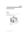
$VVHPEO\
)OXVK0RXQWLQJ 0RXQWLQJ3RVLWLRQ 6XUIDFH0RXQWLQJ &RQYHUWHU0RGXOHV 7KHUPDO8WLOL]DWLRQ,QGLFDWRU ,QVWDOODWLRQDQG:LULQJ
*HQHUDO 0DLQ&LUFXLWV &RQWURO&LUFXLWV Chapter 5 — Setting the Operational Parameters
0HQX2YHUYLHZ
0DLQ6HWWLQJV 6SHFLDO6HWWLQJV 2SHUDWLQJ3DUDPHWHUV Chapter 6 — Commissioning and Operation
&KHFNLQJWKH,QVWDOODWLRQ &KHFNLQJWKH:LULQJ &KHFNLQJWKH,QVWDOODWLRQZLWKWKH&RQWURO9ROWDJH$SSOLHG
6ZLWFKLQJRQWKH&RQWURO9ROWDJH &KHFNLQJWKH6HW3DUDPHWHUV 0RWRU&XUUHQW /RFNHG5RWRURU6WDUWLQJ&XUUHQW /RFNHG5RWRU7LPH
Publication 825-UM001B-EN-P January 2001
iv
Table of Contents
3URJUDPPLQJ6HWXSDQG2SHUDWLRQ 6WDUWLQJ
2SHUDWLQJ
Chapter 7 — Testing and Maintenance
*HQHUDO &KHFNLQJZLWKRXW7HVW(TXLSPHQW )XQFWLRQDO&KHFNZLWKWKH7HVW%XWWRQ ,QGLFDWLRQRI5HFRUGHG9DOXHV &KHFNLQJZLWK7HVW(TXLSPHQW
7HVW8QLW
Chapter 8 — Error Diagnosis and Troubleshooting
$ODUP:DUQLQJ 3URFHGXUHZKHQ$ODUP:DUQLQJ3LFNV8S
7ULS )DXOW&RGHV
3URFHGXUHLI´$/$50µGRHVQRW5HVHW 3URFHGXUHLI´75,3µFDQQRWEH5HVHW
Chapter 9 — Applications/Wiring
%XOOHWLQ6PDUW0RWRU0DQDJHUZLWK&RQWDFWRUV 0DLQ&LUFXLW
&RQWURO&LUFXLW 6WDU'HOWD6WDUWHUZLWK%XOOHWLQ6PDUW0RWRU0DQDJHU 0DLQ&LUFXLW
&RQWURO&LUFXLW 6KRUW&LUFXLW3URWHFWLRQRI0HGLXP+LJK9ROWDJH0RWRUV 0DLQ&LUFXLWZLWK&DW1R0672SWLRQ&DUG &RQWURO&LUFXLW 7ZR6SHHG0RWRUV 0DLQ&LUFXLW 7ZR6SHHG0RWRU$6SHHG,$6SHHG,,$ 0DLQ&LUFXLW
7ZR6SHHG0RWRUVZLWK3ULPDU\&XUUHQW7UDQVIRUPHU 3ULPDU\&LUFXLW 6HSDUDWHO\9HQWLODWHG0RWRUV
Publication 825-UM001B-EN-P January 2001
Table of Contents
v
%DVLF8QLWDQG&RQYHUWHU0RGXOHZLWK3ULPDU\&XUUHQW7UDQVIRUPHU
DQG&RUH%DODQFH&XUUHQW7UDQVIRUPHU 0DLQ&LUFXLW
%DVLF8QLWDQG&RQYHUWHU0RGXOHZLWK&RUH%DODQFH&XUUHQW
7UDQVIRUPHU 0DLQ&LUFXLW 0RWRUVZLWK/RZ,GOLQJ&XUUHQW H 0DLQ&LUFXLW &RQQHFWLQJWKH377HPSHUDWXUH6HQVRUV8VLQJWKH
&RQGXFWRU7HFKQLTXH %DVLF8QLWDQG&RQYHUWHU0RGXOHZLWK3ULPDU\&XUUHQW7UDQVIRUPHU
3KDVH&XUUHQW(YDOXDWLRQ 7LPH&XUUHQW&KDUDFWHULVWLFRI%XOOHWLQ 6PDUW0RWRU0DQDJHU Chapter 10 — References
Figures
)LJXUH
)LJXUH
)LJXUH
)LJXUH
)LJXUH
)LJXUH
)LJXUH
)LJXUH
)LJXUH )LJXUH )LJXUH )LJXUH )LJXUH )LJXUH )LJXUH )LJXUH %XOOHWLQ6PDUW0RWRU0DQDJHU 2SHUDWLQJ&KDUDFWHULVWLFVRIDQ$&0RWRU $&&XUUHQW3URILOHRID0RWRU6WDUWLQJ
'LUHFWRQ/LQH 7HPSHUDWXUH5LVH&KDUDFWHULVWLFV
RI0RWRU:LQGLQJV 5HGXFWLRQLQ$YHUDJH/LIH(0RID0RWRU
ZKHQ:LQGLQJLV&RQWLQXRXVO\2YHUKHDWHG 0RGXODU'HVLJQRIWKH%XOOHWLQ
6PDUW0RWRU0DQDJHU %ORFN'LDJUDP )URQW9LHZZLWK2SHUDWLQJ(OHPHQWV 6HWWLQJ0RGH 0HQX6HOHFWLRQ (QWHULQJD'DWD9DOXH 6HOHFWLQJWKH$FWXDO9DOXHV 6HOHFWLQJ5HFRUGHG'DWD %DVLF8QLW7HVW%XWWRQ
7ZR%RG\6LPXODWLRQRIWKH+HDWLQJ8S
RID0RWRU 7ULS&KDUDFWHULVWLF« V Publication 825-UM001B-EN-P January 2001
vi
Table of Contents
)LJXUH )LJXUH )LJXUH )LJXUH )LJXUH )LJXUH )LJXUH )LJXUH )LJXUH )LJXUH )LJXUH )LJXUH )LJXUH )LJXUH )LJXUH )LJXUH )LJXUH )LJXUH )LJXUH )LJXUH )LJXUH )LJXUH )LJXUH )LJXUH )LJXUH
)LJXUH
)LJXUH
7ULS&KDUDFWHULVWLFV«V 5HGXFWLRQLQ3HUPLVVLEOH0RWRU2XWSXW
'XHWR9ROWDJH$V\PPHWU\SHU,(&DQG1(0$ )XQFWLRQRI+LJK2YHUORDGDQG-DP3URWHFWLRQ )XQFWLRQRI8QGHUORDG3URWHFWLRQ 3KDVH&XUUHQW'HWHFWLRQ ([DPSOHRI3KDVH&XUUHQW6HQVLQJ ,VRODWHG1HWZRUN(DUWK)DXOW
RQWKH1HWZRUN6LGH 1HWZRUN(DUWKHGWKURXJKD+LJK,PSHGDQFH
(DUWK)DXOWRQWKH1HWZRUN6LGH ,VRODWHGQHWZRUN(DUWK*URXQG)DXOWRQWKH/HDGV
RQWKH0RWRU6LGH 1HWZRUN(DUWKHGWKURXJKD+LJK,PSHGDQFH
(DUWK*URXQG)DXOWRQWKH0RWRU/HDGV ,VRODWHG1HWZRUN(DUWK*URXQG)DXOW
LQWKH0RWRU 1HWZRUN(DUWKHGWKURXJKD+LJK,PSHGDQFH
(DUWK*URXQG)DXOWRQWKH0RWRU /LPLWLQJWKH1XPEHURI6WDUWVSHU+RXU 0RQLWRULQJ6WDUWLQJ7LPH &XUUHQWDQG7HPSHUDWXUH&XUYHVIRU:DUPDQG
&ROG0RWRU6WDUWVDQGWKH6PDUW0RWRU0DQDJHU
7ULSSLQJ/LPLWV ([DPSOHIRUW[H VDQG
:DUP7ULS7LPH ,QWHUUXSWLRQRID6KRUW&LUFXLW 6WDOOLQJ'XULQJ6WDUWLQJ &KDUDFWHULVWLFRI37&6HQVRUVDVSHU,(& $QDORJ2XWSXWIRU0RWRU7HPSHUDWXUH5LVH $QDORJ2XWSXWIRU0RWRU7HPSHUDWXUH $QDORJ2XWSXWIRU0RWRU&XUUHQW 2SHUDWLQJ'LDJUDPIRU7LPHU)XQFWLRQV 'LDJUDPRI6WDU'HOWD:\H'HOWD6WDUWLQJ %DVLF8QLW0RXQWHGLQDQ(QFORVXUH 0RXQWLQJ3RVLWLRQ %DVLF8QLW0RXQWHGLQWR3DQHO0RXQWLQJ)UDPH
&DW1R)30 Publication 825-UM001B-EN-P January 2001
Table of Contents
)LJXUH
)LJXUH
)LJXUH
)LJXUH
)LJXUH
)LJXUH
)LJXUH
)LJXUH
)LJXUH
)LJXUH
)LJXUH
)LJXUH
)LJXUH
)LJXUH
)LJXUH
)LJXUH
)LJXUH
)LJXUH
)LJXUH
)LJXUH
)LJXUH
)LJXUH
)LJXUH
)LJXUH
)LJXUH
)LJXUH
)LJXUH
)LJXUH
)LJXUH
vii
&DW1RV0&00&00&0 &DW1RV0&00&01 &DW1R07807KHUPDO8WLOL]DWLRQ,QGLFDWRU
%DVLF8QLW+RXVLQJZLWK2SWLRQ&DUGV %DVLF8QLWZLWK&RQYHUWHU0RGXOH 3KDVH&XUUHQW(YDOXDWLRQ
3KDVH&XUUHQW(YDOXDWLRQ
6PDUW0RWRU0DQDJHU%DVLF8QLW
&DW1R0672SWLRQ&DUG &DW1R0/92SWLRQ&DUG &DW1R0092SWLRQ&DUG 5DQJHRI6WDUWLQJ&XUUHQWVRI6WDQGDUG0RWRUV
([SUHVVHGDV0XOWLSOHRIWKH5DWHG6HUYLFH
&XUUHQW
7HVWZLWKD3KDVH&XUUHQW6RXUFH 7HVWZLWKD6LQJOH3KDVH&XUUHQW6RXUFH %DVLF8QLWDQG&RQYHUWHU0RGXOH &RQWUROE\0RPHQWDU\&RQWDFW %DVLF8QLWDQG&RQYHUWHU0RGXOH &RQWUROE\0RPHQWDU\&RQWDFW %DVLF8QLWIRU6KRUW&LUFXLW3URWHFWLRQ &RQWUROE\0RPHQWDU\&RQWDFW 7ZR6SHHG$SSOLFDWLRQ8WLOL]LQJ2QH0&0 7ZR6SHHG$SSOLFDWLRQ8WLOL]LQJ0&0 7ZR6SHHG$SSOLFDWLRQ8WLOL]LQJ3ULPDU\&XUUHQW
7UDQVIRUPHU
7\SLFDO$SSOLFDWLRQ8WLOL]LQJ3ULPDU\&XUUHQW
7UDQVIRUPHUVDQG&RUH%DODQFH&XUUHQW
7UDQVIRUPHU
7\SLFDO$SSOLFDWLRQ8WLOL]LQJ&RUH%DODQFH&XUUHQW
7UDQVIRUPHU
$SSOLFDWLRQZLWK/RZ,GOLQJ&XUUHQW &RQGXFWRU7HFKQLTXHIRU37:LULQJ 7\SLFDO$SSOLFDWLRQ8WLOL]LQJ3KDVH&XUUHQW
(YDOXDWLRQZLWK3ULPDU\&XUUHQW7UDQVIRUPHUV 7ULS&KDUDFWHULVWLFV Publication 825-UM001B-EN-P January 2001
viii
Table of Contents
Tables
7DEOH$
7DEOH%
7DEOH&
7DEOH'
7DEOH(
7DEOH)
7DEOH*
7DEOH+
7DEOH,
7DEOH$
7DEOH%
7DEOH&
7DEOH'
7DEOH(
7DEOH)
7DEOH*
7DEOH+
7DEOH,
7DEOH7DEOH.
7DEOH/
7DEOH0
7DEOH1
7DEOH2
7DEOH3
7DEOH4
7DEOH5
7DEOH6
7DEOH7
7DEOH8
7DEOH9
7DEOH:
(QYLURQPHQWDO5DWLQJV 1RPLQDO5DWHG9ROWDJHV8H (OHFWULFDO5DWLQJV 6XSSO\5DWLQJV 5HOD\5DWLQJV 7HUPLQDOV 0DLQ&XUUHQW7UDQVIRUPHU5DWLQJV 5HFRPPHQGHG'DWDIRU&RUH%DODQFH&XUUHQW
7UDQVIRUPHU
&RQYHUWHU0RGXOH³5HODWHG(UURU0HVVDJHV
$FWXDO9DOXHV2YHUYLHZ 6HW9DOXHV2YHUYLHZ 5HFRUGHG9DOXHV2YHUYLHZ 'LVSOD\([DPSOHRI6HW9DOXHV0HQX 'LVSOD\([DPSOHRI$FWXDO9DOXHV0HQX 'LVSOD\([DPSOHRI5HFRUGHG9DOXHV 3URWHFWLYH)XQFWLRQV6XPPDU\ :DUQLQJ)XQFWLRQV6XPPDU\ &RQWURO)XQFWLRQV6XPPDU\ 7KHUPDO2YHUORDG6HWWLQJ3DUDPHWHUV 3URWHFWLRQ$JDLQVW7KHUPDO2YHUORDG $V\PPHWU\3KDVH8QEDODQFH
6HWWLQJ3DUDPHWHUV +LJK2YHUORDGDQG-DP6HWWLQJ3DUDPHWHUV 8QGHUORDG6HWWLQJ3DUDPHWHUV (DUWK*URXQG)DXOW³+ROPJUHHQ5HVLGXDO
6HWWLQJ3DUDPHWHUV &RUH%DODQFH&XUUHQW7UDQVIRUPHU
6HWWLQJ3DUDPHWHUV (DUWK*URXQG)DXOW&RUH%DODQFH
6HWWLQJ3DUDPHWHUV 6WDUWVSHU+RXU6HWWLQJ3DUDPHWHUV 0RQLWRULQJ6WDUW7LPH6HWWLQJ3DUDPHWHUV :DUP6WDUW6HWWLQJ3DUDPHWHUV
$ODUP([DPSOHV 5HVHW6HWWLQJ3DUDPHWHUV 6KRUW&LUFXLW6HWWLQJ3DUDPHWHUV Publication 825-UM001B-EN-P January 2001
Table of Contents
7DEOH;
7DEOH<
7DEOH=
7DEOH$$
7DEOH$%
7DEOH$&
7DEOH$'
7DEOH$(
7DEOH$)
7DEOH$
7DEOH%
7DEOH&
7DEOH$
7DEOH%
7DEOH&
7DEOH'
7DEOH$
7DEOH$
7DEOH$
ix
6WDOOLQJGXULQJ6WDUW6HWWLQJ3DUDPHWHUV 37&6HWWLQJ3DUDPHWHUV 6HQVRU0HDVXULQJ&LUFXLW6SHFLILFDWLRQV 3KDVH6HTXHQFH6HWWLQJ3DUDPHWHUV 3KDVH)DLOXUH6HWWLQJ3DUDPHWHUV
6WDU'HOWD:\H'HOWD6WDUWLQJ
6HWWLQJ3DUDPHWHUV 377HPSHUDWXUH'HWHFWRU5HVLVWDQFH
SHU,(& 3757'6HWWLQJ3DUDPHWHUV
0RWRU,QVXODWLRQ&ODVV6HWWLQJ3DUDPHWHUV &DW1RV0&00&00&0 &DW1RV0&00&01 6SHFLILFDWLRQV 0DLQ6HWWLQJV 6SHFLDO6HWWLQJV &RPPXQLFDWLRQ6HWWLQJV &DW1R0«2SHUDWLQJ3DUDPHWHUV &KHFNLQJWKH$FWXDO9DOXHV /LVWRI5HFRUGHG9DOXHV 3RVVLEOH&DXVHVDQG$FWLRQV Publication 825-UM001B-EN-P January 2001
x
Table of Contents
Notes:
Publication 825-UM001B-EN-P January 2001
Chapter
1
Introduction
Why Have an Electronic Control and Protection System?
7KHQHHGWRRSWLPL]HSURGXFWLRQIDFLOLWLHVUHTXLUHVHQKDQFHGFRQWUROPRQLWRULQJDQG
SURWHFWLRQV\VWHPV
0RWRUDQGLQVWDOODWLRQXVHPXVWEHPD[LPL]HGZKLOHPLQLPL]LQJERWKWKHGRZQWLPHUHTXLUHG
IRUPDLQWHQDQFHDQGWKDWFDXVHGE\PRWRUIDLOXUHVWKHVHUHTXLUHPHQWVDUHHDVLO\PHWE\WKH
PLFURSURFHVVRUEDVHG%XOOHWLQ6PDUW0RWRU0DQDJHU
7KH%XOOHWLQ6PDUW0RWRU0DQDJHUKDVDPRGXODUGHVLJQDQGLVHDVLO\SURJUDPPHG,WV
DWWULEXWHVHQDEOHDQRSWLPXPILWWRDZLGHYDULHW\RIPRWRUDQGLQVWDOODWLRQUHTXLUHPHQWV
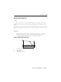
7KH%XOOHWLQ6PDUW0RWRU0DQDJHUSURYLGHVFRQWLQXRXVPRQLWRULQJRIPRWRURSHUDWLQJ
GDWDLQRQHRIWZRZD\V7KHGDWDFDQEHYLHZHGGLUHFWO\RQWKHXQLWRULWFDQEHPRQLWRUHG
UHPRWHO\YLDDQHWZRUNE\XVLQJD3&RUSURFHVVFRPSXWHU7KHPDLQVWDWLVWLFDOGDWDFDQDOVR
EHDFFHVVHGDWDQ\WLPH
Figure 1.1 Bulletin 825 Smart Motor Manager
Publication 825-UM001B-EN-P January 2001
1-2
Introduction
Operational Demands of the Motor/Drive
Temperature Rise
0RWRUGHVLJQVDQGDSSOLFDEOHVWDQGDUGVUHTXLUHWKDWZKHQDPRWRULVRSHUDWHGXQGHU
VSHFLILHGORDGVDQGDPELHQWFRQGLWLRQVWKHFULWLFDOSDUWVRIWKHPRWRUZLOOUHPDLQZLWKLQDQ
DOORZDEOHWHPSHUDWXUHUDQJHDQGVKRUWWHUPRYHUORDGVZLOOQRWKDUPWKHPRWRU
7KHGHYLFHSURWHFWLQJWKHPRWRUPXVWSHUPLWIXOOXVHRIWKHPRWRUDQGLWVHFRQRPLFDO
RSHUDWLRQ$WWKHVDPHWLPHWKHSURWHFWLYHGHYLFHPXVWVZLWFKRIIUDSLGO\LIDQRYHUORDG
RFFXUV
Motor Operating Characteristics
(OHFWULFPRWRUVDEVRUEHOHFWULFDOHQHUJ\DQGVXSSO\PHFKDQLFDOHQHUJ\'XULQJWKLVHQHUJ\
FRQYHUVLRQORVVHVDUHSURGXFHGLQWKHIRUPRIKHDW7KHWRWDOORVVFRQVLVWVRIWKHIROORZLQJ
VHSDUDWHORVVHV
• /RVVHVLQGHSHQGHQWRIWKHFXUUHQWWKHVHORVVHVDUHYLUWXDOO\FRQVWDQWLHWKH\DOVR
RFFXUDWQRORDG
• ,URQORVVHVFDXVHGE\UHPDJQHWL]DWLRQDQGHGG\FXUUHQWV
• 0HFKDQLFDOORVVHVFDXVHGE\IULFWLRQDQGYHQWLODWLRQ
• /RVVHVGHSHQGHQWRQWKHFXUUHQWWKHVHORVVHVLQFUHDVHZLWKORDGLHZLWKWKHFXUUHQW
FRQVXPHGE\WKHPRWRU
• +HDWORVVHVFDXVHGE\WKHFXUUHQWLQWKHVWDWRU
• +HDWORVVHVFDXVHGE\WKHFXUUHQWLQWKHURWRU
• ,QFUHDVHGWHPSHUDWXUHULVHFDXVHGE\SRRUFRROLQJHJFRROLQJILQVDUHGXVW\RU
GDPDJHGFRRODQWWHPSHUDWXUHLVWRRKLJK
Publication 825-UM001B-EN-P January 2001
Introduction
1-3
I Pv
cos ϕ, η, n
⎯ ⎯
⎯
ne, Ie, Pve
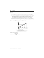
Figure 1.2 Operating Characteristics of an AC Motor
P
Pe
Pv
Pve
e
n
ne
ns
cos ϕ
η
1.5
1.4
1.3
1.2
1.1
Ie ns
1.0
n
0.9
η
0.8
0.7
cos ϕ
0.5
I
Pv
25
50
75
100
Power
Rated operational power
Power losses
Power losses under rated conditions
Operational current
Rated service current
Speed
Rated operational speed
Synchronous speed
Power factor
Efficiency
125
P
⎯ [%]
Pe
Operating characteristics of an AC motor as a function of load. Between no load and half load, the losses increase only slightly
with rising load. Between half load and rated load, the change in efficiency is minimal, and the power factor approaches its
maximum. The losses increase approximately proportional to the load. Above rated load, the losses increase more rapidly than
the load.
Current and Temperature Curves
3RZHUORVVLVDSSUR[LPDWHO\SURSRUWLRQDOWRWKHVTXDUHRIWKHPRWRUFXUUHQW7KHSRWHQWLDO
IRUPRWRUKD]DUGVH[LVWVPDLQO\GXULQJVWDUWLQJDQGLQDORFNHGURWRUFRQGLWLRQ:KHQD
ORFNHGURWRUFRQGLWLRQH[LVWVWKHPD[LPXPYDOXHRIWKHVWDUWLQJFXUUHQWIORZVDSSUR[LPDWHO\
«WLPHVWKHUDWHGVHUYLFHFXUUHQW,HDQGDOORIWKHSRZHUDEVRUEHGLVFRQYHUWHGLQWRKHDW
$VWKHPRWRUVSHHGLQFUHDVHVWKHSRZHUFRQYHUWHGLQWRKHDWGHFUHDVHV%XWLIWKHURWRU
UHPDLQVORFNHGWKHWHPSHUDWXUHRIWKHVWDWRUDQGURWRUZLQGLQJVULVHVFRQVLGHUDEO\FDXVHGE\
WKHKLJKORVVHVDQGWKHVKRUWWLPHWKDWKHDWFDQIORZLQWRWKHODPLQDWHGFRUH,IWKHPRWRULV
QRWVZLWFKHGRIITXLFNO\WKHVWDWRURUURWRUZLQGLQJFDQEXUQRXW
$IWHUVWDUWXSWKHWHPSHUDWXUHRIWKHZLQGLQJULVHVDFFRUGLQJWRWKHORDGDQGFRROLQJRIWKH
PRWRU,QWLPHWKHZLQGLQJUHDFKHVLWVVWHDG\VWDWHYDOXH
$KLJKFXUUHQWUHVXOWVLQDFRUUHVSRQGLQJO\KLJKRSHUDWLQJWHPSHUDWXUH
Publication 825-UM001B-EN-P January 2001
1-4
Introduction
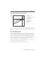
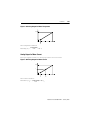
Figure 1.3 AC Current Profile of a Motor Starting Direct-on-Line
2 2 Ie
1.6 2 IA
I
2 2 IA
A Starting current
tA Starting time
e Rated service
current
t Time
tA
Oscillogram of switching on a squirrel-cage induction motor by direct-on-line starting. The high motor starting current A flows
during the starting time (tA). If this is less than the limit specified by the manufacturer (usually 10 s), the starting current does not
cause an excessive temperature rise. The brief, asymmetrical peak when switching on can be ignored.
0RWRUVDUHQRWWKHUPDOO\KRPRJHQHRXV7KHZLQGLQJVWDWRULURQDQGURWRUKDYHGLIIHUHQW
KHDWFDSDFLWLHVDQGFRQGXFWLYLWLHV)ROORZLQJXQGXO\KHDY\ORDGVHJGXULQJVWDUWLQJ
WHPSHUDWXUHHTXDOL]DWLRQRFFXUVEHWZHHQWKHYDULRXVSDUWVRIWKHPDFKLQHKHDWIORZVIURP
WKHZDUPHUZLQGLQJLQWRWKHFRROHULURQXQWLOWKHWHPSHUDWXUHGLIIHUHQFHLVPLQLPDO
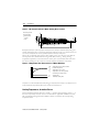
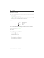
Figure 1.4 Temperature Rise Characteristics of Motor Windings
ϑ
ϑG
ϑK
ϑs
ϑe
ϑG
ϑe
ϑs
ϑK
0t t
A B
t
tA
tB
Temperature limit of the insulation
Coolant temperature
Temperature rise at start
Temperature rise when operated
continuously at rated current
Starting time
Permitted stalling time
Temperature rise in a motor winding. During the starting time (tA), the temperature of the winding rises very rapidly; at the end of
startup, the temperature drops temporarily because heat is transferred to the laminated core.
Limiting Temperatures, Insulation Classes
7KHSHUPLVVLEOHWHPSHUDWXUHOLPLWIRUDZLQGLQJ³DQGWKXVWKHORDGEHDULQJFDSDFLW\³RI
WKHPRWRULVSULPDULO\DIXQFWLRQRIWKHPRWRU
VLQVXODWLRQ$SSOLFDEOHVWDQGDUGV8/&6$
,(&DQG1(0$GLVWLQJXLVKEHWZHHQGLIIHUHQWFODVVHVRILQVXODWLRQDQGFRUUHVSRQGLQJ
WHPSHUDWXUHOLPLWV
Publication 825-UM001B-EN-P January 2001
Introduction
1-5
Insulation Aging
7KHDJLQJRILQVXODWLRQPDWHULDOLVDFKHPLFDOSURFHVVWKDWLVDFFHOHUDWHGE\FRQWLQXRXV
RYHUWHPSHUDWXUH,WPD\EHDVVXPHGWKDWDZLQGLQJWHPSHUDWXUHWKDWLVFRQVWDQWO\ .
KLJKHUWKDQWKHWHPSHUDWXUHOLPLWUHGXFHVWKHPRWRUOLIHE\KDOI7KLV´OLIHODZµVKRZVWKDW
SDUWLFXODUDWWHQWLRQPXVWEHSDLGWRDGKHULQJWRWKHSHUPLWWHGRSHUDWLQJWHPSHUDWXUHIRUORQJ
SHULRGVRIWLPH1RWHWKDWRYHUWHPSHUDWXUHVRIVKRUWGXUDWLRQDQGLQIUHTXHQWRFFXUUHQFHGR
QRWVHULRXVO\DIIHFWWKHOLIHRIWKHPDFKLQH
7KH%XOOHWLQ6PDUW0RWRU0DQDJHU
VDELOLW\WRDFFXUDWHO\OLPLWH[FHVVLYHFXUUHQW
FRQGLWLRQVJUHDWO\DLGVLQH[WHQGLQJPRWRUOLIH,QSUDFWLFHLWPD\EHH[SHFWHGWKDWWKHUHZLOO
EHUHGXFHGORDGVDQGSDXVHVVRWKDWZKHQWKHWHPSHUDWXUHOLPLWLVUHDFKHGWKHPRWRUOLIHZLOO
QRWEHLPSDLUHG
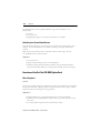
Figure 1.5 Reduction in Average Life (EM) of a Motor when Winding is
Continuously Overheated
%
100
EM
ϑG
EM
Average motor life
Temperature limit of the insulation
70
50
25
0
+5K
+10K
+15K
+20K
ϑG
Rotor Temperature
7KHURWRUVRIVTXLUUHOFDJHLQGXFWLRQPRWRUVZLWKVLPSOHFRQVWUXFWLRQQRLQVXODWLRQPD\
FRQWLQXRXVO\DWWDLQKLJKHUWHPSHUDWXUHVWKDQURWRUVLQPRWRUVZLWKLQVXODWHGZLQGLQJV
+RZHYHULQODUJHUPRWRUVWKHFRQFHQWUDWLRQRIWKHURWRUORVVHVGXULQJVWDUWLQJLVKLJKHUWKDQ
WKHFRQFHQWUDWLRQVRIORVVHVLQRWKHUSDUWVRIWKHPRWRU7KHVWDUWLQJWLPHRIVXFKPRWRUVLV
WKHUHIRUHOLPLWHGE\WKHWKHUPDOFDSDFLW\RIWKHURWRU7KHVHW\SHVRIPRWRUVDUHFRPPRQO\
UHIHUUHGWRDV´URWRUFULWLFDOµPRWRUV&ULWLFDOWRWKHURWRUDUHWKHPHFKDQLFDOVWUHVVHVFDXVHG
E\WKHWHPSHUDWXUHULVHXQVROGHULQJRIWKHURWRUEDUVDQGIRU(([HPRWRUVPRWRUVIRUXVH
LQWKHFKHPLFDOLQGXVWU\WKHKLJKWHPSHUDWXUHDVDVRXUFHRILJQLWLRQ
Operational Requirements for Installation
0RQLWRULQJWKHDSSOLFDWLRQSDUDPHWHUVDQGSURFHVVGDWDRIDQLQVWDOODWLRQFDQEHYHU\
LPSRUWDQW(YHQDVOLJKWFKDQJHLQWKHVWDUWLQJDQGRSHUDWLQJEHKDYLRURIWKHPRWRUFDQ
LQGLFDWHDQLPSHQGLQJIDXOW7KH6PDUW0RWRU0DQDJHUKHOSVHOLPLQDWHSRWHQWLDOWURXEOH
EHIRUHPDMRUUHSDLUVDUHQHFHVVDU\DQGORVVRISURGXFWLRQRFFXUV
Publication 825-UM001B-EN-P January 2001
1-6
Introduction
7KH6PDUW0RWRU0DQDJHUIXOILOVWKHVHUHTXLUHPHQWVE\SURYLGLQJSURWHFWLRQDJDLQVWWKH
IROORZLQJ
• KLJKRYHUORDGVWDOOLQJDQGMDP
• XQGHUORDG
• SKDVHVHTXHQFH
Personnel and Installation Safety
3HUVRQQHOSURWHFWLRQLQWKHYLFLQLW\RIFRQWUROHTXLSPHQWLVRISULPDU\LPSRUWDQFH7KH
FRUUHVSRQGLQJUHTXLUHPHQWVRIUHJXODWRU\DJHQFLHVDUHWKHUHIRUHEHFRPLQJLQFUHDVLQJO\
VHYHUH7KH6PDUW0RWRU0DQDJHUUHIOHFWVWKLVE\SURYLGLQJWKHIROORZLQJSURWHFWLRQ
• HTXLSPHQWFRQVWUXFWLRQ
• WRXFKSURWHFWLRQ
• LQVXODWHGKRXVLQJ
• PRWRUSURWHFWLYHIXQFWLRQV
• (DUWKJURXQGIDXOW
• +LJKRYHUORDGVWDOOLQJDQGMDP
• :URQJGLUHFWLRQRIURWDWLRQ
Bulletin 825 Smart Motor Manager as an Automation
Component
7KH%XOOHWLQ6PDUW0RWRU0DQDJHUGHWHFWVDEQRUPDORSHUDWLQJFRQGLWLRQVDQGIDXOWVLQ
PRWRUEUDQFKFLUFXLWV7KHGDWDPDGHDYDLODEOHE\WKH6PDUW0RWRU0DQDJHUFDQEHXVHGIRU
RSHUDWLRQDOFRQWURODQGRSWLPL]DWLRQRIWKHLQVWDOODWLRQ
$ODUJHQXPEHURIVXSHUYLVRU\SURWHFWLYHDQGFRQWUROIXQFWLRQVLPSURYHRSHUDWLRQDOFRQWURO
DQGDYRLGXQQHFHVVDU\GRZQWLPH7KLVPD[LPL]HV\RXUPRWRULQYHVWPHQWPDNLQJWKH6PDUW
0RWRU0DQDJHUDYDOXDEOHFRPSRQHQWLQPRGHUQDXWRPDWLRQV\VWHPV
Publication 825-UM001B-EN-P January 2001
Chapter
2
Equipment Description
System Structure
7KH%XOOHWLQ6PDUW0RWRU0DQDJHULVDPLFURSURFHVVRUEDVHGSURWHFWLRQDQGFRQWURO
V\VWHPIRUPRWRUV)RUWKH$&PRWRUDQGWKHRSHUDWHGLQVWDOODWLRQWKLVPHDQV
• 0D[LPXPXWLOL]DWLRQ
• &RQWLQXRXVVXSHUYLVLRQ
• 5HOLDEOHSURWHFWLRQ
7KHPRGXODUVWUXFWXUHRIWKHV\VWHPDQGDOORILWVSRVVLEOHIXQFWLRQVHQDEOHWKH%XOOHWLQ
6PDUW0RWRU0DQDJHUWREHHFRQRPLFDOO\DQGRSWLPDOO\DGDSWHGWRDQ\LQVWDOODWLRQ
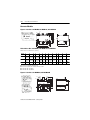
System Components
7KHPRWRUSURWHFWLRQV\VWHPFRQVLVWVRI
•
•
•
•
•
7KHEDVLFFRQWURODQGSURWHFWLRQXQLW
&XUUHQWFRQYHUWHUPRGXOHVIRU«$
&DEOHIRUFRQQHFWLQJEHWZHHQWKHEDVLFXQLWDQGWKHFXUUHQWFRQYHUWHUPRGXOH
2SWLRQDOSOXJLQSULQWHGFLUFXLWERDUGV
7KHUPDOXWLOL]DWLRQPHWHUWRLQGLFDWHWKHWKHUPDOORDG
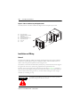
Installation
7KH6PDUW0RWRU0DQDJHUFDQEHHLWKHUIOXVKPRXQWHGLQDQHQFORVXUHGRRURUVXUIDFH
PRXQWHGWRWKHHQFORVXUHPRXQWLQJSODWHXVLQJDSDQHOPRXQWLQJIUDPH
&XUUHQWFRQYHUWHUPRGXOHVFDQEHVXUIDFHPRXQWHG
Publication 825-UM001B-EN-P January 2001
2-2
Equipment Description
Modular Design
7KH&DW1R0EDVLFXQLWFDQEHILWWHGZLWKDGGLWLRQDORSWLRQIXQFWLRQFDUGVWRVXLWWKH
UHTXLUHPHQWV
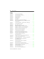
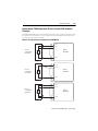
Figure 2.1 Modular Design of the Bulletin 825 Smart Motor Manager
Basic unit, Cat. No. 825-M…
Option:
Cat. No. 825-MLV
Cat. No. 825-MMV
PT100
Communication
Communication
Network
Cat. No. 825-MST
Thermal utilization module
4...20 mA
Core Balance Current Transformer
Converter module
$YDLODEOH&RPPXQLFDWLRQV&DUGV
&DW1R0'1'HYLFH1HW
&DW1R5,25HPRWH,2➊
&DW1R0%60RGEXV➊
&DW1R03%352),%86)06
➊ Available from Prosoft Technology, Inc. (not an Allen-Bradley product). References to third-part products are
provided for informational purposes only. Prosoft Technology, Inc., is solely responsible for the accuracy of
information, supply, and support of this product. For further information regarding this particular referenced
product, please contact Prosoft Technology, Inc., in the U.S. at (661) 664-7208 or your local Prosoft
Technology, Inc. distributor.
Publication 825-UM001B-EN-P January 2001
ϑamb
M
3~
∑
825MCM
PT100 #7
(RTD)
Phase failure
Phase
sequence
7T1/7T2/7T3
L1
L2
L3
Control
inputs
PT100 #1…#6
(RTD)
F
#2
#1
Thermistor
overload
Earth fault
Remote reset
825-MDN
3600-RIO
Ambient temperature
825-MMV
825-MLV
825-MST
825-M
LCD
Stator /
bearing temperature
Basic unit
825-M
Controller
Operation
Communication Interface
Disable settings
Emergency start
Supply
1T1/1T2/1T3
…6T1/6T2/6T3
L1
L2
L3
Y31
Y32
Y41
24 V AC/DC
Y42
24 V AC/DC
T1, T2
k, l
Y21
Y22
A1 (-) A2 (+) +
Y11
Y12
Y13
3600-MBS 825-MPB
4…20 mA
PLC
PC
Choice
825-MLV or 825-MMV
Auxiliary relay #4
Auxiliary relay #5
53/54
Auxiliary relay #3
Analog output
43/44
I+ / I-
63/64
Auxiliary relay #1
Auxiliary relay #2
23/24
33/34
Alarm relay AL
Main relay MR
Warning/Trip
13/14
95/96
97/98
Network
L1 L2 L3
Equipment Description
2-3
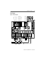
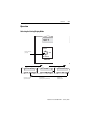
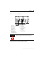
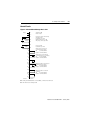
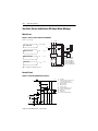
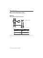
Block Diagram
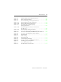
Figure 2.2 Block Diagram
Publication 825-UM001B-EN-P January 2001
2-4
Equipment Description
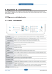
Operating Elements
7KH6PDUW0RWRU0DQDJHULVYHU\HDV\WRRSHUDWH$OOIXQFWLRQVGDWDDQGWHVWVFDQEH
HQWHUHGH[HFXWHGRUGLVSOD\HGXVLQJWKHVL[PHPEUDQHNH\VDQGWKHVLQJOHOLQH/&'ZKLFK
GLVSOD\VDOODYDLODEOHGDWDDQGIXQFWLRQV
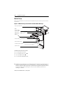
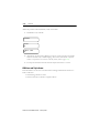
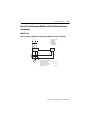
Figure 2.3 Front View with Operating Elements
➊
➋
➏
➌
➍
➎
➊ Fault indicator (LED)
Flashing: warning
Steady state: trip
➋ LCD: Single line (two lines of text are displayed alternately)
➌ Values: Selection of mode
Actual: Indication of actual operational data
Set: Setting mode (set/modify, store parameters)
Recorded: Indication of statistical data
➍ Select: Select function and enter/change operating parameter
➎ Settings: Enable entry (Change) and memorize (Enter)
➏ Test: Verifies operation of Smart Motor Manager.
➐ Reset: Enables the Smart Motor Manager after a trip.
Publication 825-UM001B-EN-P January 2001
➐
Equipment Description
2-5
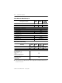
Specifications — Basic Unit and Converter Module
Table 2.A Environmental Ratings
Temperature
Operation
-5…+ 60 °C (23…140 °F)
Storage
-40…+ 60 °C (-40…140 °F)
Transport
-40…+ 85 °C (-40…185 °F)
Climatic Withstand
Damp heat IEC 68-2-3
Climatic cycling IEC 68-2-30
40 °C (104 °F), 92%
relative humidity, 56 days
25/40 °C (77/104 °F), 21 cycles
Enclosure Protection Class
825-M, enclosed in panel
IP65
Terminals
IP20
Resistance to Vibration
as per IEC 68-2-6
10…150 Hz, 3 G
Resistance to Shock
as per IEC 68-2-27
30 G, shock duration 18 ms, half a sine wave in x, y, z
directions
Publication 825-UM001B-EN-P January 2001
2-6
Equipment Description
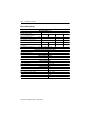
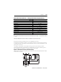
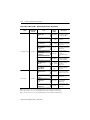
Table 2.B Nominal Rated Voltages Ue
825MCM2
Primary Detection Circuit
825MCM180
MCM630
MCM630N
825MCM20
Motor Circuit
as per IEC, SEV, VDE 0660
as per CSA, UL
400V AC
240V AC
660V AC
600V AC
1 000V AC
600V AC
Control Circuit
Main relay (MR) 95…98, supply A1, A2
Phase sequence protection L1, L2, L3
as per IEC 947
as per SEV
as per UL, CSA
Alarm relay (AL) 13/14
Auxiliary relay #1, #4, #5
as per IEC 947
as per SEV
as per UL, CSA
Auxiliary relays #2, #3
Control inputs #1, #2
400V AC
380V AC
240V AC
400V AC
250V AC
240V AC
50V AC/30V AC
24V AC/DC
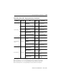
Table 2.C Electrical Ratings
Test Voltage
825MCM2
Motor Circuit
Uimp
as per IEC 947-1
2.5 kV
Control Circuit
Between control circuits and to all other circuits ➊
Main relay (MR) 95…98,
supply A1, A2
Phase sequence protection
L1, L2, L3
Alarm relay (AL), auxiliary relay
#1, #4, #5 as per IEC 947-4
Core balance current transformer k, I
Control inputs #1, #2
Auxiliary relays #2, #3
as per IEC 947-4
825MCM20
825MCM180
MCM630
825-MCM630N
Uimp
6 kV
Uimp
8 kV
Uimp
12 kV
Uimp
4 kV
Uimp
2.5 kV
➊ The measuring inputs for PT100 and PTC, the 4…20 mA output, and the communication interface are not
isolated from one another.
Publication 825-UM001B-EN-P January 2001
Equipment Description
2-7
Standards
(0&
1RLVHHPLVVLRQDVSHU(1DQGDVSHU(1
1RLVHSURRIDVSHU(1DQGDVSHU(1
6WDQGDUGV,(&&6$&1R8/
$SSURYDOV&(8//LVWHG&6$37%3K\VNDOLVFK7HFKQLVFKH%XQGHVDQVWDOW*HUPDQ\
&HUWLILFDWLRQUHTXLUHGIRUPRWRUSURWHFWLRQLQH[SORVLRQKD]DUGDUHDHJ&KHPLFDO
3HWURFKHPLFDO,QVWDOODWLRQV
Table 2.D Supply Ratings
Nominal supply voltage Us
Permissible voltage fluctuation
50/60 Hz, 22…24, 33…36, 44…48, 110…120, 220…240,
380…415, 440V AC
24…48, 72…120, 220V DC
AC 0.85…1.10 US
DC 0.80…1.10 US for 24…48V DC
DC 0.80…1.20 US for 72…120V DC
DC 0.80…1.15 US for 220V DC
Power consumption
Short-circuit protection
AC 13 VA, DC 10 W max.
With the appropriate supply cable rating, the supply module is
short-circuit proof.
Publication 825-UM001B-EN-P January 2001
2-8
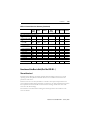
Equipment Description
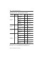
Table 2.E Relay Ratings
Contacts fitted
Nominal operating voltage
as per UL, CSA: pilot duty 240 V
Continuous thermal current
Rated operating current for AC-15
Max. permissible switching current
(cos ϕ = 0.3) AC-15
Rated operating current for DC-13
without prot. network,
L/R = 300 ms
Max. rated current of back-up fuse:
Contact Data of Output Relays
Main Relay (MR) 95…96
1 N/C and 1 N/O contact, galvanically separated
[V]
24
220…250
380…440
[A]
[A]
4
3
110…125
3
1.2
[A]
30
30
12
[A]
2
0.2
–
[A]
10 A, 500V AC, Type gG
0.3
Alarm Relay (AL), Auxiliary Relays #1, #4, #5
Contacts fitted
1 N/O contact each
Continuous thermal current
4A
Max. permissible switching voltage
400V AC, 125 VDC
Nominal Operating Current
cos ϕ = 1
4 A at 250V AC or 30V DC
cos ϕ = 0.4, L/R = 7 ms
2 A at 250 VAC or 30V DC
Max. Switching Power
cos ϕ = 1
1 250 VA, 150 W
cos ϕ = 0.4, L/R = 7 ms
500 VA, 60 W
as per UL/CSA
240 V, 1 A pilot duty
Auxiliary Relays #2, #3
Contacts fitted
1 N/O contact each
Continuous thermal current
4A
Max. permissible switching voltage
48 VAC, 30 VDC
Max. Switching Power
cos ϕ = 1
150 W
cos ϕ = 0.4, L/R = 7 ms
60 W
Publication 825-UM001B-EN-P January 2001
Equipment Description
2-9
Table 2.F Terminals
Cat. No. 825-M plug-in terminals
as per UL
as per VDE
Range of gauges:
0.5…2.5 m2, single wire (AWG No. 20…14)
0.5…1.5 m2 double wire (AWG No. 20…16)
AWG No. 22…14
nominal gauge 1.5 mm 2
Main circuit
825-MCM2/
825-MCM20
825-MCM180
825-MCM630(N)
Terminals: 2 x 2.5 mm2/1 x 4 mm2
(2 x 0.0039 in2/1 x 0.006 in2)
2 x AWG No. 20…14/1 x AWG No. 20…12
Aperture or busbars:
Wire ∅ 19 mm max. 20/16 x 4 mm
Bus bars: 25 x 8 mm
Publication 825-UM001B-EN-P January 2001
2-10
Equipment Description
Main Current Transformers for the Motor Circuit
:KHQWKH&DW1R0&RQWURODQG3URWHFWLRQ8QLWLVXVHGDVDVHFRQGDU\UHOD\ZLWK&DW
1RV0&0DQG0&0WKHIROORZLQJVSHFLILFDWLRQVDSSO\
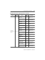
Table 2.G Main Current Transformer Ratings
Minimum nominal operating voltage
Minimum rated primary current 1n
Rated secondary current
Class and nominal
overcurrent factor
Nominal operating voltage of motor
Nominal operating current of motor
1 A or 5 A
5 P 10 ext. 120% ➊
According to power consumption in leads
Power rating
and measuring circuits
Rated frequency
50/60 Hz
825-M +
825-M +
Burden:
825-MCM2
825-MCM20
0.1 VA/phase
0.4 VA/phase
Power consumption at max. rated current ➋
Continuous thermal current
3A
24 A
Thermal current, 1 s duration
250 A
600A
Frequency of input current
50/60 Hz
50/60 Hz
General Notes on 825-MCM…
An open-circuit secondary is permitted, as the burden is
No-load
installed in the detection module
➊ Designation according to IEC 60044 part 2:
5
Total measurement error (percentage):
±5% within range up to rated nominal overcurrent (10X)
±1% at rated nominal primary current
P
For protection purposes
10
Rated nominal overcurrent factor: 10X rated nominal primary current
ext.
120%
Extended rated thermal current: 120% of rated nominal primary current (if e motor > 87% of
rated nominal transformer current)
With starting current 10 e: class 5 P 20
The current transformer error in addition to the basic unit error
➋ 2.5 A with Cat. No. 825-MCM2, 20 A with Cat. No. 825-MCM20
Publication 825-UM001B-EN-P January 2001
Equipment Description
2-11
Core Balance Current Transformer
Table 2.H Recommended Data for Core Balance Current Transformer
minimum detectable earth (ground) fault
Pickup current of basic unit earth (ground) fault protection
Burden: Measuring circuit 825-M…
Power consumption at max. rated current
Continuous thermal current
Thermal current, 1 s duration
Frequency of input current
Nominal ratio Kn =
0.4 VA
0.5 A
25 A
50/60 Hz
$FRUHEDODQFHFXUUHQWWUDQVIRUPHUFXUUHQWUDWLR LVDYDLODEOHDQGPLJKWVXLWPRVW
DSSOLFDWLRQV0D[HDUWKJURXQGIDXOW FXUUHQW $
Short-Circuit Protection
Choosing a Circuit Breaker or Fuse and Associated Contactor
7KHEUDQFKFLUFXLWVKRUWFLUFXLWSURWHFWLYHGHYLFHVHULHVFLUFXLWEUHDNHURUIXVHPXVWDVVXUH
WKDWWKHPRWRUFDQVWDUWZKLOHLQWHUUXSWLQJVKRUWFLUFXLWFXUUHQWVUDSLGO\HQRXJKWRSUHYHQW
GDPDJHWRWKHLQVWDOODWLRQ7RDLGLQWKHODWWHUWKHIXVHUDWLQJVKRXOGEHDVORZDVSRVVLEOH
7KHORZHVWSRVVLEOHIXVHUDWLQJGHSHQGVRQWKHVWDUWLQJFXUUHQWRIWKHPRWRUDQGWKHWULSSLQJ
WLPHVHWRQWKH6PDUW0RWRU0DQDJHU
The Short-Circuit Coordination of the Starter Must Always be Taken into Account
7KHFRQWDFWRUUHFHLYHVLWVWULSSLQJVLJQDOZKHQWKH6PDUW0RWRU0DQDJHUEDVLFXQLWWULSV7KH
EDVLFXQLWLQWHUUXSWVDOOFXUUHQWXSWRWKHSRLQWRILQWHUVHFWLRQZLWKWKHWLPHFXUUHQW
FKDUDFWHULVWLFVRIWKHFLUFXLWEUHDNHURUIXVH
:KHQVWDUWLQJODUJHPRWRUVWKHPDLQFRQWDFWVRQWKHFRQWDFWRUDUHVXEMHFWHGWRKLJKWKHUPDO
ORDGV,IWKHPRWRUVWDUWLQJWLPHH[FHHGVDFHUWDLQOLPLWWKHPD[LPXPSHUPLVVLEOHFXUUHQWKDV
WREHUHGXFHG
7KHUDWLQJRIWKHIXVHRUFRQWDFWRUPXVWDOVRDOORZIRUWKHSURVSHFWLYHVKRUWFLUFXLWFXUUHQW
7KH%XOOHWLQFRQYHUWHUPRGXOHVDUHVKRUWFLUFXLWSURRI
7KHFRRUGLQDWLRQJUDGLQJGLDJUDPVIRUFRQWDFWRUVDUHDYDLODEOHRQUHTXHVW
Publication 825-UM001B-EN-P January 2001
2-12
Equipment Description
Response Supply Voltage Failure
,IWKHVXSSO\YROWDJHIDLOVWKHVHWWLQJGDWDDUHUHWDLQHG
Failure of Supply Voltage > 30 ms
•
•
•
•
•
$OOHQHUJL]HGRXWSXWUHOD\VGURSRXW
7KH/('H[WLQJXLVKHV
7KHWLPHUIRU´GXUDWLRQRIVXSSO\IDLOXUHµVWDUWVPD[LPXPK
7KHLQVWDQWDQHRXVVHWDQGVWDWLVWLFDOGDWDDUHUHFRUGHG
7KH/&'H[WLQJXLVKHV
Recovery of the Supply Voltage
• ,QLWLDOL]DWLRQURXWLQHLVVWDUWHG
• 7KHWLPHRIRFFXUUHQFHDQGWKHGXUDWLRQRIWKHVXSSO\IDLOXUHDUHHQWHUHGLQWR
PHPRU\
• 7KHWKHUPDOLPDJHLVFDOFXODWHGDQGXSGDWHG
• $OORXWSXWUHOD\VUHWXUQWRWKHVWDWHEHIRUHWKHVXSSO\IDLOXUHH[FHSWIRUUHOD\DQG
ZKHQFRQWUROLVH[HFXWHGYLDFRPPXQLFDWLRQ
• /&'DQG/('DFWLYDWH
Publication 825-UM001B-EN-P January 2001
Equipment Description
2-13
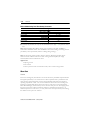
Automatic Recognition of Converter Module
7KH%XOOHWLQUHJXODUO\FKHFNV
• 7KHOLQNEHWZHHQWKHEDVLFXQLWDQGWKHFRQYHUWHUPRGXOH
• 9HULILHVWKDWWKHIXOOORDGFXUUHQWVHWRQWKHEDVLFXQLWLVZLWKLQWKHUDQJHRIWKH
FRQYHUWHUPRGXOH
• 7KHVXSHUYLVRU\FLUFXLWV
,QWKHHYHQWRIDIDXOWWKHRXWSXWUHOD\05WULSVDQGWKHW\SHRIIDXOWLVGLVSOD\HGRQWKH/&'
Table 2.I Converter Module — Related Error Messages
Verify
Verification that FLC on basic
unit is within range of converter
module
Sequence
• After switching on supply
• Supervision while motor is stationary
• When running, as soon as the link is
interrupted the basic unit will trip and
display one or more of the following
causes:
• short circuit, thermal, earth fault
(Holmgreen = residual),
asymmetry, overcurrent
• After switching on supply
• After each change in setting of rated
current
Supervisory circuits
• Continuous monitoring (hardware
errors, supply, etc.)
Link between basic unit and
converter module
Display
825-MCM NOT CON
Ie OUT OF RANGE
ERROR 825-MCM
Publication 825-UM001B-EN-P January 2001
Chapter
3
Functions
Menu Overview
Actual Values
,Q´$FWXDO9DOXHVµPRGHDOORSHUDWLQJSDUDPHWHUVFDQEHVHOHFWHGDQGUHDGIURPWKH/&'
Table 3.A Actual Values Overview
Display List
Option Card
Cat. No.
Page
Display List
Option Card
Cat. No.
Page
I MOTOR
A
—
6-6
I earth - H
%I
—
6-7
I MOTOR
%e
—
6-5
I earth - C
mA
—
6-7
I1
%e
—
6-6
Tambient
ºC
825-MMV
6-7
I2
%e
—
6-6
PT100 #1(…6)
ºC
825-MMV
6-7
I3
%e
—
6-6
PROBUS
—
825-MPB
6-7
TRIP IN
s
—
6-6
RIO
—
3600-RIO
6-7
RESET IN
s
—
6-7
MODBUS
—
3600-MBS
6-7
ASYM
%
—
6-7
DevNet
—
825-MDN
6-7
Publication 825-UM001B-EN-P January 2001
Functions
3-2
Set Values
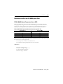
7KHSDUDPHWHUV´0DLQ6HWWLQJVµDQG´6SHFLDO6HWWLQJVµPXVWEHSURJUDPPHGIRUHYHU\
DSSOLFDWLRQ7KHRWKHUSDUDPHWHUVHJ´+LJK2YHUORDGµ´$V\PPHWU\µKDYHIDFWRU\VHW
YDOXHVZKLFKDUHFRUUHFWIRUPRVWDSSOLFDWLRQV
Table 3.B Set Values Overview
Parameter List
THERMAL TRIP
Option
Card
Cat. No.
Page
—
5-4
Parameter List
THERMAL RESET LEVEL
Option
Card
Cat. No.
Page
—
5-10
THERMAL WARNING
—
5-4
COOLING CONSTANT RATIO
—
5-10
ASYMMETRY TRIP
—
5-5
PTC TRIP
825-MST
5-10
ASYMMETRY WARNING
—
5-5
PTC RESET
825-MST
5-10
OVERCURRENT TRIP
—
5-5
CONTROL INPUT #1
5-10
OVERCURRENT WARNING
—
5-5
DELAY AUX REL # 2
5-10
EARTH FAULT PROTECTION
—
5-6
SPEED SWITCH
EARTH FAULT HOLMGREEN TRIP
—
5-6
DISABLE FUNCTION
5-11
825-MST
5-7
CONTROL INPUT #2
5-12
EARTH FAULT CORE TRIP
EARTH FAULT CORE WARNING
825-MST
5-7
DELAY AUX REL #3
SHORT CIRCUIT PROTECTION
825-MST
5-7
NEW FULL LOAD CURRENT
UNDERLOAD TRIP
—
5-8
PHASE REVERSAL TRIP
UNDERLOAD WARNING
—
5-8
PHASE LOSS TRIP
STAR DELTA STARTING
825-MST
825-MST
5-11
5-12
5-12
825-MLV
5-13
5-13
825-MLV
5-8
PT100 PROTECTION
WARM STARTING
—
5-9
PT100 RESET/WARNING
START INHIBIT
—
5-11
OUTPUT 4…20 mA
START CONTROL
—
5-9
STATION NUMBER
—
5-16
MAIN RELAY CONNECTION
—
5-10
REL #2-3 VIA COM
—
5-16
825-MMV
5-13
825-MST
5-15
ALARM RELAY CONNECTION
—
5-10
CLEAR RECORDED VALUES
—
5-16
THERMAL RESET
—
5-10
FACTORY SETTINGS
—
5-16
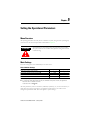
ATTENTION
$OOSDUDPHWHUVFDQEHVHWLQFOXGLQJWKRVHIXQFWLRQVDVVRFLDWHGZLWK
RSWLRQERDUGVWKDWKDYHQRWEHHQPRXQWHGLQWKHGHYLFH+RZHYHU
WKHVHZDUQLQJDQGWULSIXQFWLRQVDUHQRWRSHUDWLRQDOXQOHVVWKH
FRUUHVSRQGLQJRSWLRQERDUGLVLQVWDOOHG
Publication 825-UM001B-EN-P January 2001
3-3
Functions
Recorded Values
,Q´5HFRUGHGYDOXHVµPRGHDOOUHFRUGHGGDWDFDQEHVHOHFWHGDQGUHDGIURPWKH/&'
Table 3.C Recorded Values Overview
Option
Card
Cat. No.
Display List
Page
Display List
Option
Card
Cat. No.
Page
825-M MAIN TIME
h min.
—
7-2
CAUSE 2PRV TRIP
—
—
7-3
MOTOR RUNNING HR
h min.
—
7-2
CAUSE 3PRV TRIP
—
—
7-3
SINCE LAST START
h min.
—
7-2
CAUSE 4PRV TRIP
—
—
7-3
SINCE 1PRV START
h min.
—
7-2
SINCE EMG START
h min.
—
7-3
SINCE 2PRV START
h min.
—
7-2
SINCE POWER OFF
h min.
—
7-3
SINCE 3PRV START
h min.
—
7-2
DURATION POW OFF
h min.
—
7-3
SINCE 4PRV START
h min.
—
7-2
I BEF LAST TRIP
%e
—
7-3
SINCE LAST TRIP
h min.
—
7-2
AS BEF LAST TRIP
%
—
7-3
SINCE 1PRV TRIP
h min.
—
7-3
EF BEF LAST TRIP
mA,
%e
—
7-3
SINCE 2PRV TRIP
h min.
—
7-3
MAX T BEF LAST TRIP
ºC
825-MMV
7-4
SINCE 3PRV TRIP
h min.
—
7-3
TH BEF LAST TRIP
%
—
7-4
SINCE 4PRV TRIP
h min.
—
7-3
NUMBER START
—
—
7-4
CAUSE LAST TRIP
—
—
7-3
—
—
7-4
CAUSE 1PRV TRIP
—
—
7-3
NUMBER TRIP (TH,
AS, OC, EF, SC, UL,
PTC, PR, PL, PT100)
Publication 825-UM001B-EN-P January 2001
Functions
3-4
Operation
Selecting the Setting/Display Mode
SET
Actual
Change mode by
pressing
Set
Recorded
Values
ACTUAL VALUES
Actual
Indication of actual
operational data
Change
SET VALUES
Actual
RECORDED VALUES
Change
Setting mode
(set/vary, store parameters)
Actual
Change
Indication of
statistical data
Publication 825-UM001B-EN-P January 2001
3-5
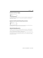
Functions
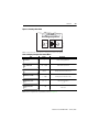
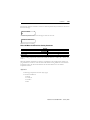
Setting the Operation Parameters (Set Values)
7H[WDQGGDWDDUHLQGLFDWHGDOWHUQDWHO\DSSUR[LPDWHO\VWH[WDQGVGDWD2QWKH´VHFRQG
OLQHµWKHGDWDWKDWLVIDFWRU\VHWRUVXEVHTXHQWO\PRGLILHGLVGLVSOD\HG)XQFWLRQVQRW
DFWLYDWHG2))DUHQRWLQGLFDWHG
7RVHWWKHRSHUDWLRQSDUDPHWHUVUHSHDWHGO\SUHVVWKH9DOXHVEXWWRQXQWLO´6(7
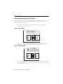
9$/8(6µDSSHDUVRQWKHGLVSOD\
Figure 3.1 Setting Mode
SET VALUES
Actual
Change
Set
Recorded
Enter
Values
Select
Settings
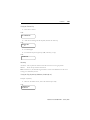
3UHVV6HOHFW8SRU'RZQXQWLOWKHGHVLUHGSDUDPHWHUHJ´)8///2$'&855µ
DQG´$PSµDSSHDUVGLVSOD\DOWHUQDWHVEHWZHHQWH[WDQGGDWD
Figure 3.2 Menu Selection
35 AMP
FULL LOAD CURR
Change
Actual
Set
Enter
Recorded
Values
Select
Settings
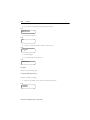
3UHVVWKH6HWWLQJV&KDQJHEXWWRQRQFH7KHVHWYDOXHEHJLQVWRIODVK$QHZVHWYDOXH
FDQQRZEHHQWHUHGE\PHDQVRIWKH6HOHFWNH\V8SRU'RZQ7KHHQWU\LVFRPSOHWHG
E\SUHVVLQJ6HWWLQJV(QWHU
Publication 825-UM001B-EN-P January 2001
Functions
3-6
Figure 3.3 Entering a Data Value
35 AMP
Actual
Change
Set
Recorded
Values
Enter
Select
Settings
1RWH +ROGGRZQWKH6HOHFWEXWWRQWRFKDQJHWKHYDOXHVPRUHTXLFNO\
Table 3.D Display Example of Set Values Menu
LCD
SET VALUES
Range
Description
—
Mode: setting parameters
0.5…2 000
Rated motor current in A
No/Yes
Primary current transformer in use
PRIMARY C.T. RATIO
1
1…2 000
Primary current transformer ratio
LOCKED ROT CURR
6 x Ie
2.5…12
Locked rotor current as
___ e
LOCKED ROT TIME
10 sec
1…600
Maximum permitted time for the rotor to be stalled
from cold
FULL LOAD CURR
20 A
PRIMARY C.T.
NO
1RWH )RUDFRPSOHWHOLVWRISDUDPHWHUVUHIHUWR&KDSWHU Publication 825-UM001B-EN-P January 2001
3-7
Functions
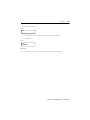
Indications of Actual Values
,Q´$FWXDO9DOXHVµPRGHDOORSHUDWLQJSDUDPHWHUVFDQEHVHOHFWHGDQGUHDGIURPWKH/&'
3UHVV9DOXHVXQWLO´$&78$/9$/8(6µDSSHDUVRQWKHGLVSOD\
3UHVV6HOHFW8SRU'RZQXQWLOWKHGHVLUHGLQIRUPDWLRQLVGLVSOD\HG
Figure 3.4 Selecting the Actual Values
ACTUAL VALUES
Actual
Change
Set
Recorded
Enter
Values
Select
Settings
I MOTOR 00 % Ie
Actual
Change
Set
Recorded
Values
Enter
Select
Settings
Table 3.E Display Example of Actual Values Menu
LCD
Range
Description
—
Display of the actual
values
I MOTOR…A
0.00…49.99
50…24 000
Motor current in A
TH UTILIZ…%
0…100
Thermal utilization
0/20…999
Motor current as percent of rated current
ACTUAL VALUES
I MOTOR…% Ie
1RWH )RUDFRPSOHWHOLVWRISDUDPHWHUVUHIHUWR&KDSWHU Publication 825-UM001B-EN-P January 2001
Functions
3-8
Applications
7KH´$FWXDO9DOXHVµPRGHSURYLGHV
• $VVLVWDQFHGXULQJSURJUDPPLQJDQGVHWXS
• 9HULILFDWLRQDIWHUPDLQWHQDQFHRUSURGXFWLRQFKDQJH
• &RQWLQXRXVRSHUDWLRQDOVXSHUYLVLRQ
Indications of Recorded Values (Statistics)
,Q´5HFRUGHG9DOXHVµPRGHDOOUHFRUGHGGDWDFDQEHVHOHFWHGDQGUHDGIURPWKH/&'
3UHVV9DOXHVXQWLO´5(&25'('9$/8(6µDSSHDUVRQWKHGLVSOD\
3UHVV6HOHFW8SRU'RZQXQWLOWKHGHVLUHGVWDWLVWLFDOLQIRUPDWLRQLVGLVSOD\HG
Figure 3.5 Selecting Recorded Data
RECORDED VAL
Actual
Change
Set
Recorded
Values
Enter
Select
Settings
2 h 28 min
SINCE LAST TRIP
Actual
Change
Set
Recorded
Values
Enter
Select
Settings
Publication 825-UM001B-EN-P January 2001
3-9
Functions
Table 3.F Display Example of Recorded Values
LCD
Description
RECORDED VALUES
Display of the statistical data
825-M MAIN TIME
_ _ _ H_ _ _MIN
Bulletin 825-M* running time (including interruption ≤ 8 hour of control
voltage in hours, minutes)
MOTOR RUNNING TIME
_ _ _h_ _ _min
Total motor running time in hours, minutes
1RWH )RUDFRPSOHWHOLVWRISDUDPHWHUVUHIHUWR&KDSWHU Applications
7KH´5HFRUGHG9DOXHVµPRGHSURYLGHV
• $QDO\VLVRIPRWRUIDXOWVDQGSURGXFWLRQLQWHUUXSWLRQV
• $QDO\VLVRISUHPDWXUHPRWRUIDLOXUHV
• $PHDQVRIGHWHUPLQLQJPDLQWHQDQFHMREVRQWKHVZLWFKJHDUPRWRUDQGLQVWDOODWLRQ
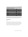
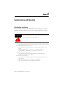
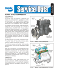
Test Button
:KHQWKHPRWRULVDWVWDQGVWLOOWKHDODUPVWULSVDQGWULSSLQJWLPHVRIWKHSURWHFWLYH
IXQFWLRQVFDQEHFKHFNHGZLWKRXWH[WHUQDODLGVE\SUHVVLQJWKH7HVWEXWWRQ
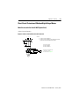
Figure 3.6 Basic Unit Test Button
SMART MOTOR
MANAGER
Change
Test
Enter
Settings
Publication 825-UM001B-EN-P January 2001
Reset
Functions
3-10
Testing the Thermal Trip
3UHVVWKH7HVW EXWWRQ
/&'
TEST THERMAL ON
$IWHUWKHVHWEORFNLQJWLPHKDVH[SLUHGWKHEDVLFXQLWPXVWWULS
/&'
LOCK ROT TIME
_ _ _sec
7KH/('OLJKWV
7KHVHOHFWHGRXWSXWUHOD\SLFNVXS05PDLQUHOD\RQWULS
/&'
THERMAL TRIP
Resetting
$XWRPDWLF 7KHWULSEHFRPHVLQDFWLYHZKHQWKH7HVW EXWWRQLVQRORQJHUSUHVVHG
0DQXDO
5HVHWWKHWULSZLWKWKH5HVHWEXWWRQ
1RWH $IWHUWKHWHVWWKHWKHUPDOLPDJHUHVXPHVLWVFRUUHFWVWDWH6LPXODWLRQRIWKHPRWRU
FRROLQJLVQRWDIIHFWHGE\WKHWHVW
Testing the Trips (Asymmetry/Unbalance, Underload, etc.)
([DPSOH$V\PPHWU\
:KHQLQ´6HW9DOXHVPRGHµDFFHVVWKHVHOHFWHGRXWSXWUHOD\
/&'
ASYMMETRY TRIP
AUX RELAY #2
Publication 825-UM001B-EN-P January 2001
3-11
Functions
,IQRRXWSXWLVDVVLJQHGWKHIROORZLQJUHDGRXWDSSHDUV
/&'
ASYMMETRY TRIP
NO OUTPUT RELAY
3UHVVWKH7HVW EXWWRQ
/&'
TEST
$IWHUWKHVHWWULSGHOD\H[SLUHVWKHEDVLFXQLWPXVWWULS
/&'
AS TRIP TIME
_ _ _sec
7KH/('OLJKWV
7KHVHOHFWHGRXWSXWUHOD\SLFNVXS
/&'
ASYMMETRY TRIP
Resetting
&DQFHOWKHWULSE\SUHVVLQJ5HVHW
Testing the Warning Functions
([DPSOH$V\PPHWU\ZDUQLQJ
:KHQLQ´6HW9DOXHVµPRGHDFFHVVWKHVHOHFWHGRXWSXWUHOD\
/&'
AS WARNING
ALARM RELAY
Publication 825-UM001B-EN-P January 2001
Functions
3-12
3UHVVWKH7HVW EXWWRQ
/&'
TEST
7KH/('IODVKHVDQGWKHVHOHFWHGRXWSXWUHOD\SLFNVXSLPPHGLDWHO\
/&'IODVKHV
/&'
TEST
AS WARNING
Resetting
$VVRRQDVWKH7HVW EXWWRQLVQRORQJHUSUHVVHGWKHXQLWZLOODXWRPDWLFDOO\UHVHW
Publication 825-UM001B-EN-P January 2001
3-13
Functions
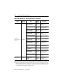
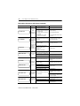
Function Summary
Table 3.G Protective Functions Summary
Thermal overload
Asymmetry (phase failure)
High overloading/jam
Underload
Underload delayed enable
Earth (ground) fault (residual)
Starting time monitor
Limited starts per hour
Short-circuit
Earth (ground) fault
(core balance c.t.)
Stalling during start
Thermistor input (PTC)
Off
5 mA…50 A
1A
0.1…5 s
—
➊
➊
—
—
—
Bulletin 825-MLV Option Card
Off
—
—
—
Off
—
—
—
Bulletin 825-MMV Option Card
Off
Off
Phase sequence (motor supply)
Phase failure (motor supply)
PT100 input #1…#6 (RTD)
(stator, bearings)
PT100 input #7 (RTD) ➋
Functions
Tripping
Factory Relays ➌ Factory
Setting Factory
Factory
Delay
Setting Selection Setting
Range
Setting
Setting
Range
Bulletin 825-M… Basic Unit
On
100%
—
—
MR, No
MR
On
5…80%
35%
1…25 s
2.5 s
All
MR
1…6 e
2.4 e
On
0.1…5 s
0.5 s
All
MR
Off
25…100% 75%
1…60 s
10 s
All
MR
On
—
—
0…240 s
0s
—
—
On
10…100% 50%
0.1…5 s
0.5 s
All
MR
Off
—
—
1…240 s
10 s
All
MR
Off
1…10
2
—
—
All
MR
Bulletin 825-MST Option Card
4…12 e
10 e 20…990 ms 50 ms
Off
#1, No
#1
0.5 s
All
MR
—
800 ms
All ➊
All
MR ➊
MR
1s
2s
All
All
MR
MR
Off
50…200 °C
50 °C
—
<8s
Off
—
—
—
—
MR, AL
#1…#3
—
MR
—
➊ Via external speedometer (control input #1), output and trip relays as for high overload.
➋ Allowing for the ambient temperature in the thermal image.
➌ Only one relay per function can be selected: MR = main relay, AL = alarm relay, auxiliary relay #1…#5 (if
auxiliary relays #2 and #3 are assigned to the communication [refer to page 5-16] they cannot be selected
here).
ATTENTION
:DUQLQJIXQFWLRQVHWWLQJVPXVWEHVXFKWKDWDVVRFLDWHGDODUPVDUH
DFWXDWHGEHIRUHDWULSRFFXUV
Publication 825-UM001B-EN-P January 2001
Functions
3-14
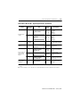
Table 3.H Warning Functions Summary
Functions
Factory
Setting
Thermal utilization
(%Δϑ load)
Asymmetry (% e)
High overloading (x e)
Underload
Earth (ground) fault
(core balance c.t.)
Tripping
Delay
Range
Bulletin 825-M… Basic Unit
Factory Relays ➊
Setting Selection
Factory
Setting
Setting
Range
Factory
Setting
Off
50…99%
75%
—
—
AL, #1…5
AL
Off
5…80%
1…6 e
20%
2 e
—
—
AL, #1…5
AL
Off
Off
—
25…100%➋ 75%➋
—
Bulletin 825-MST Option Card
—
—
AL, #1…5
AL, #1…5
AL
AL
Off
5 mA…50 A
500 mA
—
—
AL, #1…5
AL
—
AL, #1…3
AL
Bulletin 825-MMV Option Card
PT100 input #1…#6 (RTD)
(stator, bearings)
Off
50…200 °C
50 °C
—
➊ Only one relay per function can be selected: MR = main relay, AL = alarm relay, auxiliary relay #1…#5 (if
auxiliary relays #2 and #3 are assigned to the communication [refer to page 5-16] they cannot be selected
here).
➋ Same setting as for the Underload Trip function.
Publication 825-UM001B-EN-P January 2001
3-15
Functions
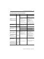
Table 3.I Control Functions Summary
Warm start (% of “cold”
trip)
Emergency override of
thermal trip ➊
Tripping
Delay
Range
Bulletin 825-M… Basic Unit
Functions
Factory
Setting
Setting
Range
Factory
Setting
Off
50…100%
70%
4…60 min. ➋
60 min.
➋
—
—
—
—
—
—
—
—
—
Factory Relays Factory
Setting Selection Setting
Bulletin 825-MST Option Card
Analog output assigned
4…20 mA
to:
0…100%
thermal utilization
On
—
—
—
—
50…200 °C
PT100 max.
0…200% e
temperature
Motor
Bulletin 825-MST Option Card, Control Input #1: (24V AC/DC; 8 mA)
One of 3 functions can be selected:
1) Pickup delay, relay #2
Off
—
—
0…240 s
1s
—
1) Dropout delay, relay #2
—
—
—
0…240 s
2s
—
—
Off
—
—
—
—
—
#2
#2
high overload relay
3) Disable protective functions:
Asymmetry/phase failure
Off
High overload/jam
Off
Earth (ground) fault
Off
Short-circuit
Off
Underload
Off
Limiting starts/hour
Off
PTC
Off
PT100 (RTD)
Off
—
—
—
—
—
—
—
—
—
—
—
—
—
—
—
—
—
—
—
—
—
—
—
—
—
—
—
—
—
—
—
—
—
—
—
—
—
—
—
—
—
—
—
—
—
—
—
—
2) Speed switch
➊ Terminals Y11…Y12 must be jumpered.
➋ Minimum waiting time between two warm starts.
Publication 825-UM001B-EN-P January 2001
Functions
3-16
Table 3.I Control Functions Summary (Continued)
Tripping
Functions Setting
Factory Relays Factory
Factory
Delay
Factory
Setting Selection Setting
Range
Setting
Range
Setting
Bulletin 825-MST Option Card, Control Input #2: (24V AC/DC; 8 mA)
One of three functions can be selected:
1) Pickup delay, relay
Off
—
—
0…240 s
1s
—
#3
#3
1) Dropout delay, relay
—
—
—
0…240 s
2s
—
#3
#3
0.5…
2) Set second rated
Off
20 A
—
—
—
—
current ➊
2 000 A
3) Disable protective functions:
Asymmetry/phase
Off
—
—
—
—
—
—
failure
High overload/jam
Off
—
—
—
—
—
—
Earth (ground) fault
Off
—
—
—
—
—
—
Short-circuit
Off
—
—
—
—
—
—
Underload
Off
—
—
—
—
—
—
Limiting starts/hour
Off
—
—
—
—
—
—
PTC
Off
—
—
—
—
—
—
PT100 (RTD)
Off
—
—
—
—
—
—
Bulletin 825-MLV Option Card
Y-Δ at 1.1 e Y-Δ at 1…240 s 10 s
Star-delta starting
Off
—
—
Y: #4/Δ:#5
➊ For example, when used with two-speed motors
Functions of the Basic Unit (Cat. No. 825-M…)
Thermal Overload
7KH6PDUW0RWRU0DQDJHUDFFXUDWHO\VLPXODWHVWKHUPDOFRQGLWLRQVLQWKHPRWRUIRUDOO
RSHUDWLQJPRGHV7KLVSHUPLWVPD[LPXPXWLOL]DWLRQRIDQLQVWDOODWLRQDQGDVVXUHVVDIH
SURWHFWLRQRIWKHPRWRU
7KHEDVLFXQLWXVHVDWZRERG\VLPXODWLRQWRFDOFXODWHDPRUHSUHFLVHUHSUHVHQWDWLRQRID
PRWRU·VWKHUPDOFRQGLWLRQGXULQJDOOPRGHVRIRSHUDWLRQ$WZRERG\VLPXODWLRQLQFRUSRUDWHV
WKHWHPSHUDWXUHULVHFKDUDFWHULVWLFVRIERWKWKHVWDWRUZLQGLQJVDQGWKHLURQPDVVRIWKH
PRWRULQWRWKHWKHUPDOLPDJH
7KHVLPXODWLRQRIWKH6PDUW0RWRU0DQDJHUDFFXUDWHO\UHSUHVHQWVWKHFRQGLWLRQVLQWKH
PRWRUDWDOOWLPHV
Publication 825-UM001B-EN-P January 2001
3-17
Functions
:KLOHWKHPRWRULVUXQQLQJWKHLURQORVVHVDVZHOODVORVVHVFDXVHGE\DV\PPHWU\DUHIHGWR
WKHVLPXODWLRQPRGHO$OORZDQFHIRUWKHDPELHQWWHPSHUDWXUHRIWKHPRWRUDVDQRSWLRQ
HQKDQFHVWKHPD[LPXPXWLOL]DWLRQRIWKHLQVWDOODWLRQHYHQZLWKFRQVLGHUDEOHYDULDWLRQRIWKH
WHPSHUDWXUH:LWKRXWWKHRSWLRQDOLQFOXVLRQRIWKHDPELHQWWHPSHUDWXUHRIWKHPRWRUWKH
WKHUPDOPRGHOEDVHVWKHWKHUPDOFDOFXODWLRQRQDQDPELHQWWHPSHUDWXUHRI&7KH
GLIIHUHQWFRROLQJFRQGLWLRQVRIDVHOIYHQWLODWHGPRWRUZKHQUXQQLQJDQGDWVWDQGVWLOODUH
WDNHQLQWRDFFRXQWE\WZRGLIIHUHQWWLPHFRQVWDQWV$IWHUVZLWFKLQJRIIWKHUDSLGFRROLQJRI
WKHZLQGLQJWRWKHLURQWHPSHUDWXUHDQGWKHVXEVHTXHQWVORZFRROLQJRIWKHPRWRUDVDZKROH
DUHVLPXODWHG
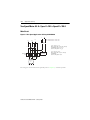
7KHWZRERG\VLPXODWLRQFDQEHUHSUHVHQWHGDVDFDSDFLWDQFHUHVLVWDQFHQHWZRUN6HH
)LJXUH Figure 3.7 Two-Body Simulation of the Heating Up of a Motor
PCu
≈ (IM2 + kIG2)
R1
PFe
S1
C1
C2
R2
R3
ϑ amb
C1
C2
R1
R2
R3
PCu
PFe
S1
M
G
ϑamb
k
Capacitance representing the heat capacity of the winding (adjustable)
Capacitance representing the heat capacity of the iron an other masses of the machine
Resistance representing resistance to heat transfer between winding and iron
Resistance representing heat dissipation to the surroundings when stationary
Resistance representing heat dissipation to the surroundings when running
Input of a current proportional to the copper losses
Input of a current proportional to the iron losses
Changeover from stationary to running
Motor current
Opposing component caused by asymmetry
Allowance for the temperature of the environment coolant (optional PT100 #7)
Constant factor according to IEC and NEMA
Adjustable Ratio of Cooling Constants
7KHUDWLRRIWKHFRROLQJFRQVWDQWZKHQWKHPRWRULVDWVWDQGVWLOOWRWKHFRROLQJFRQVWDQWZKHQ
LWLVUXQQLQJDOORZVIRUWKHGLIIHUHQFHLQFRROLQJLQWKHVHVWDWHV7KHFRROLQJFRQVWDQWUDWLRLV
VHWWRLQWKHIDFWRU\7KLVYDOXHLVFRUUHFWIRUWKHPDMRULW\RIVHOIFRROHG$&PRWRUV
)RUVHSDUDWHO\YHQWLODWHGDQGVSHFLDOPRWRUVDQGWKRVHZKLFKUHVSRQGYHU\TXLFNO\RUYHU\
VORZO\\RXPD\KDYHWRPRGLI\WKHFRROLQJIDFWRU
Publication 825-UM001B-EN-P January 2001
Functions
3-18
Indication of the Time to Tripping
/&'
TRIP IN…sec
7KLVIHDWXUHSURYLGHVFRQWLQXRXVLQGLFDWLRQRIWKHWLPHUHPDLQLQJEHIRUHWULSSLQJZKHQLQDQ
RYHUORDGFRQGLWLRQ7KLVHQDEOHV\RXWRLQWHUYHQHEHIRUHWULSSLQJRFFXUV%ODQNGLVSOD\
PHDQV7LPH! V
Indication of the Time until the Thermal Trip can be Reset
/&'
RESET IN …sec
)ROORZLQJDWKHUPDOWULSWKHEDVLFXQLWPD\QRWEHUHVHWXQWLOWKHUHVHWWKUHVKROGKDVEHHQ
UHDFKHG7KLVLVVHWWRDWHPSHUDWXUHULVHRILQWKHIDFWRU\
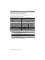
Adjustable Setting Characteristic
7KHGHJUHHRILQHUWLDFDQEHVHWWRPDWFKWKHSURSHUWLHVRIWKHPRWRU$VXLWDEOHUHIHUHQFH
YDOXHDPRQJRWKHUVLVWKHDGPLVVLEOHORFNHGURWRUWLPHRIWKHFROGPRWRULQFRQMXQFWLRQ
ZLWKWKHDVVRFLDWHGFXUUHQW7KLVPDNHVLWSRVVLEOHWRSURWHFWPRWRUVWKDWDUHWKHUPDOO\YHU\
IDVWRUYHU\VORZ6HH)LJXUH )LJXUH DQG)LJXUH
7KHWKHUPDOFDSDFLW\RIWKHLURQLVSDUWLFXODUO\LPSRUWDQWDWVPDOORYHUORDGV$OORZLQJIRUWKLV
LQWKHVLPXODWLRQHQDEOHVWKHRYHUORDGUHVHUYHVRIWKHPRWRUWREHXWLOL]HGZLWKRXWULVNLQJD
SUHPDWXUHSURWHFWLYHWULS
Publication 825-UM001B-EN-P January 2001
3-19
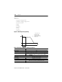
Functions
Figure 3.8 Trip Characteristic (10…30 s)
10000.0
1000.0
From cold, without pre-load
10s
20s
30s
Trip time [s]
100.0
10.0
10s
20s
30s
From warm, pre-load 1xIe
1.0
0.1
1.0 1.1
2.0
3.0
4
Load current as multiple of full load current
Publication 825-UM001B-EN-P January 2001
5
6
7
8
9
nxI e
10
Functions
3-20
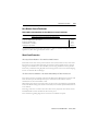
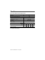
Figure 3.9 Trip Characteristics (40…100 s)
100000.0
10000.0
From cold, without pre-load
40s
60s
100s
Trip time [s]
1000.0
100.0
10.0
40s
60s
100s
From warm, pre-load 1xIe
1.0
1.0 1.1
2.0
3.0
4
Load current as multiple of full load current
.
5
6
7
8
9
10
nxI e
)RU8/&6$DSSOLFDWLRQVUHIHUWRSDJH
Publication 825-UM001B-EN-P January 2001
3-21
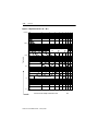
Functions
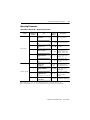
Table 3.J Thermal Overload Setting Parameters
Detection Module ➋
825-MCM20 825-MCM180 825-MCM630
Rated Current
0.5…2.5 A ➊ 2.5…20 A ➊
20…180 A
160…630 A ➌
20 A
20 A
20 A
20 A
0.01…2 A
0.1…2 A
1A
2A
Locked-Rotor Current (Multiple of Rated Current)
2.5…12 e
825-MCM2
Setting range
Factory setting
Setting increments
Setting range
Factory setting
Setting increments
825-MCM630N
160…630 A
20 A
2A
6 e
0.1 e
Locked-Rotor Time (Admissible Locked-Rotor Time of Cold Motor)
1…600 s
10 s
1s
Cooling Factor of Motor Off/On ➍
Setting range
1…10
Factory setting
2.5
Setting increments
0.5
Resetting the Thermal Trip
Setting range
10…100% of thermal utilization
Factory setting
50%
Setting increments
1%
Ultimate Release Current
1.05…1.15 e
Incl. setting tolerance
Setting range
Factory setting
Setting increments
➊
➋
➌
➍
Up to 2 000 A, if primary current transformers are used.
–5…60 °C (23…140 °F)
UL/CSA 160…434 A
The cooling factor can be modified to reflect different motor cooling with running motor and at standstill.
Publication 825-UM001B-EN-P January 2001
Functions
3-22
Table 3.K Protection Against Thermal Overload
Warning
Trip
Function
Factory setting
Setting range
Factory setting
Setting increments
Selection
Factory setting
Off
Response Level ➊
55…99%
75%
1%
Output Relay ➋
AL, #1…#5
AL
On
—
100%
—
MR, No output relay
MR
➊ Thermal utilization %
➋ If auxiliary relays #2 and #3 are assigned to the communication (refer to page 5-16) they cannot be selected
here.
Asymmetry (Phase Unbalance) and Phase Failure
$V\PPHWULFDOSKDVHYROWDJHVXVXDOO\RFFXUZKHQWKHOHDGVFORVHVWWRWKHPRWRUDUHWRRORQJ
7KHUHVXOWLQJFXUUHQWDV\PPHWU\LQWKHPRWRUZLQGLQJVPD\WKHQEH«WLPHVWKHYROWDJH
DV\PPHWU\7KH6PDUW0RWRU0DQDJHUWDNHVLQWRDFFRXQWWKHDGGLWLRQDOWHPSHUDWXUHULVHDQG
WKXVSUHYHQWVWKHOLIHRIWKHPRWRUIURPEHLQJUHGXFHG+LJKHUDV\PPHWU\RUWKHIDLOXUHRID
SKDVHFDQEHFDXVHGE\GHIHFWLYHFRQWDFWVLQFLUFXLWEUHDNHUVRUFRQWDFWRUVORRVHWHUPLQDOV
EORZQIXVHVDQGIDXOWVLQWKHPRWRULWVHOI5DSLGGHWHFWLRQDQGLQWHUUXSWLRQRIWKHVHIDFWRUV
KHOSWRSUHYHQWGDPDJHFDXVHGE\RYHUKHDWLQJLQVXFKHTXLSPHQW7KHVWUHVVRQWKH
LQVWDOODWLRQDQGWKHPRWRUEHDULQJVLVUHGXFHG7KH6PDUW0RWRU0DQDJHUPHDVXUHVWKHSKDVH
FXUUHQWVDQGFDOFXODWHVWKHWRWDOFRSSHUORVVHVDFFRUGLQJWRWKHGHILQLWLRQRIYROWDJH
DV\PPHWU\SHU,(&DQG1(0$
P
Cu
2
2
≈ ( M + k G )
'HILQLWLRQRIYROWDJHDV\PPHWU\SHU,(&DQG1(0$
Max. deviation from the average of the phase voltages × 100
ΔU ( % ) = ----------------------------------------------------------------------------------------------------------------------------Average of the phase voltages
Publication 825-UM001B-EN-P January 2001
3-23
Functions
Figure 3.10 Reduction in Permissible Motor Output Due to Voltage Asymmetry
per IEC and NEMA
fR
fR
1.0
ΔU
0.9
Reduction factor for
motor output
Voltage asymmetry
in percent
0.8
ΔU
0.7
0
1
2
3
4
5 [%]
Table 3.L Asymmetry (Phase Unbalance) Setting Parameters
Factory setting
Setting range
Factory setting
Setting increments
Setting range
Factory setting
Setting increments
Selection (relays)
Factory setting
Warning ➊
(Current Asymmetry)
Function
Off
Response Level
5…80%
20%
5%
Tripping Delay
—
—
—
Output Relay ➋
AL, #1…#5
AL
Trip ➊
On
5…80%
35%
5%
1…25 s ± 0.2 s
2.5 s ± 0.2 s
0.5 s
MR, AL, #1…#5
MR
➊ –5…60 °C (2…140 °F)
➋ If auxiliary relays #2 and #3 are assigned to the communication (refer to page 5-16) they cannot be selected
here.
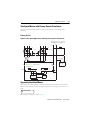
High Overload and Jam
:KHQDQRYHUORDGLVH[FHVVLYHO\KLJKDQGWKHPRWRUMDPVXQQHFHVVDU\PHFKDQLFDODQG
WKHUPDOORDGLQJRIWKHPRWRUDQGWUDQVPLVVLRQHOHPHQWVFDQEHDYRLGHGE\VZLWFKLQJWKH
PRWRURIILPPHGLDWHO\7KLVUHGXFHVFRQVHTXHQFHVRIDFFLGHQWDQGORVVRISURGXFWLRQ$
JUDGXDOLQFUHDVHLQRYHUORDGFDQEHGHWHFWHGHDUO\DQGUHSRUWHGHJEHDULQJGDPDJH7KH
SURWHFWLYHIXQFWLRQDFWLYDWHVDVVRRQDVWKHPRWRUKDVVWDUWHG
Publication 825-UM001B-EN-P January 2001
Functions
3-24
Application
•
•
•
•
•
&RQYH\LQJV\VWHPV
0LOOV
0L[HUV
&UXVKHUV
6DZVHWF
Figure 3.11 Function of High Overload and Jam Protection
I
Ie
≥ 1.2
1
3
2.4
2
1.1
t
tv
4
1
2
3
Motor start ≥ 1.2 e
Nominal operation
High overload or jam
5
tV
4
5
Tripping delay
Jam protection not active
Jam protection active (tripping threshold)
Table 3.M High Overload and Jam Setting Parameters
Factory setting
Setting range
Factory setting
Setting increments
Setting range
Factory setting
Setting increments
Selection (relays)
Factory setting
Warning ➊
Function
Off
Response Level
1…6 e
Trip ➊
On
1…6 e
2 e
2.4 e
0.2 e
0.2 e
Tripping Delay
—
—
—
Output Relay ➋
AL, #1…#5
AL
0.1…5 s ± 0.04 s
0.5 s ± 0.04 s
0.1 s
MR, AL, #1…#5
MR
➊ –5…60 °C (23…140 °F)
➋ If auxiliary relays #2 and #3 are assigned to the communication (refer to page 5-16) they cannot be selected
here.
Publication 825-UM001B-EN-P January 2001
3-25
Functions
ATTENTION
,WLVHVVHQWLDOWRVHWWKH´:DUQLQJµUHVSRQVHOHYHOWRDYDOXHOHVVWKDQ
WKH´7ULSµUHVSRQVHOHYHO
1RWH ,IWKHVWDUWLQJFXUUHQWLVEHORZ)/&WKHQWKH´0RQLWRULQJWKH6WDUW7LPHµ
IXQFWLRQPXVWEHDFWLYDWHG$IWHUWKHVHWPD[VWDUWLQJ7LPHKDVHODSVHGWKH´+LJK
2YHUORDG6WDOOµIXQFWLRQZLOOEHFRPHDFWLYH
$SSOLFDWLRQV
• 6OLSULQJPRWRUV
• 6RIWVWDUWHUV
• 0RWRUSURWHFWLRQZLWK´QRQIDLOVDIHPRGHµDIWHUDFRQWUROYROWDJHIDLOXUH
Underload
0RWRUVWKDWDUHFRROHGE\WKHPHGLXPKDQGOHGHJIDQVVXEPHUVLEOHSXPSVFDQEHFRPH
RYHUKHDWHGGHVSLWHEHLQJXQGHUORDGHG7KLVFDQEHDUHVXOWRIWKHDEVHQFHRIWKHPHGLXPRU
LQVXIILFLHQWPHGLXPGXHWRFORJJHGILOWHUVFORVHGYDOYHVHWF2IWHQWKHVHPRWRUVDUH
LQVWDOOHGLQLQDFFHVVLEOHSODFHVVRUHSDLULVOHQJWK\DQGH[SHQVLYH
7KHFRQVXPSWLRQRIOHVVWKDQDSUHVHWDSSOLFDWLRQVSHFLILFDPRXQWRIFXUUHQWPD\LQGLFDWHD
PHFKDQLFDOGHIHFWLQWKHLQVWDOODWLRQHJWRUQFRQYH\RUEHOWGDPDJHGIDQEODGHVEURNHQ
VKDIWVRUZRUQWRROV6XFKFRQGLWLRQVGRQRWKDUPWKHPRWRUEXWWKH\GROHDGWRORVVRI
SURGXFWLRQ5DSLGIDXOWGHWHFWLRQKHOSVWRPLQLPL]HGDPDJH
7KHXQGHUORDGSURWHFWLRQWULSWLPHFDQEHGHOD\HGIROORZLQJHDFKVWDUWWRSUHYHQWWULSSLQJ
7KHZDUQLQJLVDFWXDWHGDVVRRQDVWKHXQGHUORDGWKUHVKROGLVUHDFKHG
Application
•
•
•
•
6XEPHUVLEOHSXPSV
)DQV
&RQYH\RUV\VWHPV
'HWHFWLRQRIIUDFWXUHVLQPHFKDQLFDOWUDQVPLVVLRQV\VWHP
Publication 825-UM001B-EN-P January 2001
Functions
3-26
Figure 3.12 Function of Underload Protection
I
I
Ie
1
2
Ie
IT
3
3
t
tA
tp
ts
1
2
3
tA
e
tv
tp
r Tripping threshold
ts Delayed activation (underload
protection not active)
tv Tripping delay
tp Warning
Start
Nominal operation
Underload operation
Starting time
Rated current
Table 3.N Underload Setting Parameters
Factory setting
Setting range
Factory setting
Setting increments
Setting range
Factory setting
Setting increments
Setting range
Factory setting
Setting increments
Selection (relays)
Factory setting
Warning ➊
Trip ➊
Function
Off
On
Response Level
25…100% e
➋
➋
75%
➋
5%
Tripping Delay
—
1…60 s -0.2 s/+0.4 s
—
10 s
—
1s
Delayed Activation of Underload Protection
—
0…240 s +0.4 s/+0.8 s
—
0s
—
1s
Output Relay ➌
AL, #1…#5
MR, AL, #1…#5
AL
MR
➊ –5…60 °C (23…140 °F)
➋ For warning, the set Response Level is the same as the level set for tripping. If the starting current is below
1.2 FLC, then the “Monitoring the Start Time” function must be activated. After the set max. starting Time
has elapsed, the “High Overload/Stall” function will become active.
➌ If auxiliary relays #2 and #3 are assigned to the communication (refer to page 5-16) they cannot be selected
here.
Publication 825-UM001B-EN-P January 2001
3-27
Functions
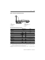
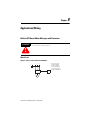
Earth (Ground) Fault
7KHLQVXODWLRQLQPRWRUVLVRIWHQGDPDJHGE\KLJKYROWDJHVXUJHVZKLFKPD\EHFDXVHGE\
OLJKWQLQJVWULNHVVZLWFKLQJRSHUDWLRQVLQWKHQHWZRUNFDSDFLWRUGLVFKDUJHVDQGSRZHU
HOHFWURQLFVHTXLSPHQW2WKHUFDXVHVDUHDJLQJDQGVXVWDLQHGRUF\FOLFRYHUORDGLQJDVZHOODV
PHFKDQLFDOYLEUDWLRQDQGWKHHQWU\RIIRUHLJQREMHFWV0RVWLQVXODWLRQIDXOWVUHVXOWLQOHDNDJH
WRWKHJURXQGHGSDUWVRIWKHPDFKLQH,QHDUWKHGJURXQGHGQHWZRUNVWKHIDXOWFXUUHQWFDQ
UDSLGO\ULVHWRDYHU\KLJKYDOXH'HSHQGLQJRQWKHW\SHRIQHWZRUNDQGLWVUHTXLUHPHQWV
PRQLWRULQJRIHDUWKJURXQGIDXOWVLVSHUIRUPHGHLWKHUE\WKHUHVLGXDOPHWKRGRUE\XVLQJD
FRUHEDODQFHFXUUHQWWUDQVIRUPHU
Earth (Ground) Fault Protection by the Holmgreen Method = Residual Method (Solidly
Earthed Networks)
7RGHWHFWDQHDUWKJURXQGIDXOWFXUUHQWLQHLWKHUDVROLGO\HDUWKHGJURXQGHGQHWZRUNRU
RQHWKDWLVHDUWKHGWKURXJKDORZLPSHGDQFHWKHFXUUHQWVLQHDFKRIWKHWKUHHSROH
FRQGXFWRUVDUHPHDVXUHG,QD´KHDOWK\µPRWRUWKLVVXPLV]HUR,IDFXUUHQWLVIORZLQJWRWKH
IUDPHRIWKHPRWRUDQGWKXVWRHDUWKDQHXWUDOFXUUHQWSURSRUWLRQDOWRWKHIDXOWFXUUHQWLV
SURGXFHGDWWKHQHXWUDORIWKHFXUUHQWWUDQVIRUPHU7KLVQHXWUDOFXUUHQWLVGHWHFWHGE\WKH
HDUWKJURXQGIDXOWGHWHFWRUDQGFDXVHVDWULS$EULHIGHOD\KHOSVWRDYRLGQXLVDQFHWULSV
FDXVHGE\WUDQVLHQWFXUUHQWWUDQVIRUPHUVDWXUDWLRQZKLFKFDQEHFDXVHGE\VZLWFKLQJ
RSHUDWLRQV7KHVHQVLWLYLW\KDVWREHVXFKWKDWQHLWKHUWUDQVIRUPDWLRQHUURUVLQWKHFXUUHQW
WUDQVIRUPHUQRUGLVWXUEDQFHVLJQDOVLQVWDUGHOWDZ\HGHOWDFRQQHFWLRQVFDXVHGE\WKHWKLUG
KDUPRQLFFDXVHQXLVDQFHWULSSLQJ
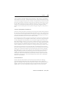
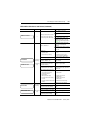
Figure 3.13 3-Phase Current Detection
Measurement of the neutral current 0 in the neutral connection of the current transformer to detect an earth (ground) fault
(residual circuit)
L1
L2
L3
P1 S1
P1 S1
P1 S1
P2 S2
P2 S2
P2 S2
1
3
5
825-MCM
I0
M1
3~
Publication 825-UM001B-EN-P January 2001
2
4
6
825-M
Functions
3-28
Table 3.O Earth (Ground) Fault — Holmgreen/Residual Setting Parameters
Trip ➊
Function
Factory setting
On
Response Level
Setting range
Factory setting
Setting increments
10…100%
50%
10%
Tripping Delay
Setting range
Factory setting
Setting increments
0.1…5 s ± 0.4 s
0.5 s
0.1 s
Output Relay ➋
Selection (relays)
Factory setting
MR, AL, #1…#5
MR
➊ –5…60 °C (23…140 °F)
➋ If auxiliary relays #2 and #3 are assigned to the communication (refer to page 5-16) they cannot be selected
here.
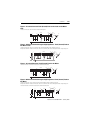
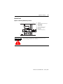
Earth (Ground) Fault Protection with a Core Balance Current Transformer
7KLVIXQFWLRQFDQEHSURYLGHGE\WKH&DW1R067RSWLRQFDUG
,QLVRODWHGKLJKLPSHGDQFHHDUWKHGRUFRPSHQVDWHGQHWZRUNVWKHQHFHVVDU\KLJKVHQVLWLYLW\
LVREWDLQHGE\XVLQJDFRUHEDODQFHFXUUHQWWUDQVIRUPHUZKRVHFRUHVXUURXQGVDOOWKUHHRIWKH
SKDVHOHDGVWRWKHPRWRU
$FFRUGLQJWRWKHSULQFLSOHRIWKHUHVLGXDOFXUUHQWSURWHFWLRQFLUFXLWEUHDNHUVHQVLWLYH
SURWHFWLRQDJDLQVWHDUWKJURXQGIDXOWVLVSRVVLEOH:LWKDORZUHVSRQVHWKUHVKROGTXLWHD
PLQRULQVXODWLRQIDXOWFDQOHDGWRDZDUQLQJRUWULSDWDQHDUO\VWDJH
Figure 3.14 Example of 2-Phase Current Sensing
Example of 2-phase current detection and core balance current transformer for sensitive earth (ground) fault protection (3-phase
current detection is also possible)
L2
L1
L3
1
5
P1 S1
P1 S1
P2 S2
P2 S2
2
6
825-MCM
3
825-M
4
S1
·
S2
M1
3~
Publication 825-UM001B-EN-P January 2001
3-29
Functions
$SSOLFDWLRQ
• +LJKYROWDJHPRWRUV
• ,QVWDOODWLRQVLQDGLIILFXOWHQYLURQPHQWZLWKPRLVWXUHGXVWHWFHJPLQHVJUDYHO
SLWVFHPHQWIDFWRU\PLOOVZRRGZRUNLQJVKRSVZDWHUSXPSLQJVWDWLRQVZDVWHZDWHU
WUHDWPHQW
Table 3.P Core Balance Current Transformer Setting Parameters
Current Ratio
Setting range
Factory setting
Setting steps
1…2 000
100
1
Table 3.Q Earth (Ground) Fault Core Balance Setting Parameters
Factory setting
Setting range
Factory setting
Setting increments
Setting range
Factory setting
Setting increments
Selection (relays)
Factory setting
Warning ➊
Function
Off
Response Level
5 mA…50 A
500 mA
5 mA
Tripping Delay
—
—
—
Output Relay ➋
AL, #1…#5
AL
Trip ➊
On
5 mA…50 A
1.0 mA
0.25 A
0.1…5 s ± 0.04 s
0.5 s
0.1 s
MR, AL, #1…#5
MR
➊ –5…60 °C (23…140 °F)
➋ If auxiliary relays #2 and #3 are assigned to the communication (refer to page 5-16) they cannot be selected
here.
Earth (Ground) Fault Protection in High-Voltage Systems
7KLVVHFWLRQSURYLGHVDQRYHUYLHZRIHDUWKJURXQGIDXOWVLQLVRODWHGKLJKLPSHGDQFHHDUWK
RUFRPSHQVDWHGQHWZRUNV
:LWKHDUWKQHXWUDOSRLQWW\SHQHWZRUNVWKHPDJQLWXGHRIWKHHDUWKJURXQGIDXOWOHDN
FXUUHQWLVGHWHUPLQHGE\WKHHDUWKFDSDFLWDQFHRIWKHQHWZRUNDQGWKHHDUWKUHVLVWDQFHRUWKH
FRPSHQVDWLQJUHDFWRU%HFDXVHWKHVL]HRILQGXVWULDOQHWZRUNVLVOLPLWHGHDUWKIDXOWFXUUHQWV
DUHYHU\VPDOO7RDJUHDWH[WHQWHDUWKFDSDFLWDQFHVDUHGHWHUPLQHGE\WKHFDEOHVDQGWKH
PRWRUV
7KHFDSDFLWDQFHYDOXHVIRUFDEOHVDUHJLYHQLQFDEOHWDEOHVDQGUDQJHIURPDSSUR[LPDWHO\
«μ)NP$YDOXHEHWZHHQ«μ)SHU0:RIPRWRUUDWLQJFDQEHDVVXPHG
IRUKLJKYROWDJHPRWRUV
Publication 825-UM001B-EN-P January 2001
Functions
3-30
$UXOHRIWKXPEIRULQGXVWULDOPHGLXPYROWDJHQHWZRUNVLVWRDOORZDERXW$RIFDSDFLWLYH
HDUWKFXUUHQWIRUHYHU\ « N9$RIV\VWHPSRZHU8VXDOO\WKHGLVSODFHPHQWYROWDJH
LVPHDVXUHGDWDVLQJOHQHXWUDOSRLQWDQGLVDVVXPHGWREHUHSUHVHQWDWLYHRIWKHHQWLUHQHWZRUN
7KHHDUWKJURXQGIDXOWLVORFDOL]HGE\XVLQJDQHDUWKJURXQGIDXOWFXUUHQWGHWHFWRUVXFKDV
WKH6PDUW0RWRU0DQDJHUZLWKHDUWKJURXQGIDXOWSURWHFWLRQLQWKHPRWRUIHHGHUV2IWHQ
RSHUDWLRQFDQFRQWLQXHVLQFHWKHHDUWKFXUUHQWVDUHFRPSDUDWLYHO\LQVLJQLILFDQWDQGWKH
LQVXODWLRQRIWKHQRQIDXOW\SKDVHVFDQEHRSHUDWHGDWDKLJKHUYROWDJHIRUDVKRUWSHULRGRI
WLPH
Isolated or High-Impedance Earth Networks
,QWKHFDVHRIHDUWKFDSDFLWDQFHVWKHQHXWUDOSRLQWRIWKHQHWZRUNDVVXPHVHDUWKSRWHQWLDODQG
WKHVXPRIWKHFXUUHQWVIORZLQJWKURXJKWKHHDUWKFDSDFLWDQFHVLV]HUR$OVRQRFXUUHQWIORZV
LQQRUPDORSHUDWLRQLQWKHKLJKYDOXHHDUWKUHVLVWRU)LJXUH )LJXUH DQG)LJXUH LQWKHFDVHRIWUDQVIRUPHUZLWKQHXWUDOSRLQW,WDYRLGVH[WUHPHRYHUYROWDJHVLQWKHHYHQWRI
LQWHUPLWWHQWHDUWKIDXOWVVXFKDVFDQRFFXULQLVRODWHGQHWZRUNV
,IIRUH[DPSOHSKDVHFRQGXFWRU)LJXUH DQG)LJXUH EHFRPHVFRQQHFWHGWRHDUWK
GXHWRDQHDUWKIDXOWWKHWZRRWKHUSKDVHFRQGXFWRUVFDUU\DOLQHWROLQHYROWDJHZLWKUHVSHFW
WRHDUWK7KURXJKWKHLUHDUWKFDSDFLWDQFHV& 1RQWKHSRZHUVXSSO\VLGHDVVHHQIURPWKH
6PDUW0RWRU0DQDJHUDQG& 0RQPRWRUVLGHDFDSDFLWLYHFXUUHQWIORZVWRZDUGHDUWKDQG
EDFNWRSKDVHFRQGXFWRUWKURXJKWKHIDXOWORFDWLRQ,QWKHFDVHRIKLJKLPSHGDQFHHDUWKLQJ
)LJXUH )LJXUH DQG)LJXUH WKHQHXWUDOSRLQWYROWDJHQRZDWDKLJKYDOXH
FDXVHVDQDGGLWLRQDOFXUUHQWWKDWLVOLPLWHGE\WKHHDUWKLQJUHVLVWRUWKURXJKWKHIDXOWORFDWLRQ
,QWKHHYHQWRIDQHDUWKIDXOWRQWKHSRZHUVXSSO\VLGHRIWKHPHDVXULQJORFDWLRQFXUUHQW
WUDQVIRUPHULQVWDOODWLRQORFDWLRQWKHEDVLFXQLWPHDVXUHVWKHFRPSRQHQWRIWKHHDUWKFXUUHQW
IORZLQJYLD& 07KHUHVSRQVHVHQVLWLYLW\PXVWEHVHOHFWHGVXFKWKDWLQWKLVFDVHWKH6PDUW
0RWRU0DQDJHUGRHVQRWWULS2QWKHRWKHUKDQGHDUWKIDXOWGHWHFWLRQE\WKH6PDUW0RWRU
0DQDJHUVKRXOGEHDVVHQVLWLYHDVSRVVLEOHVLQFHLQWKHFDVHRIHDUWKIDXOWVLQWKHPRWRU
ZLQGLQJVWKHGLVSODFHPHQWYROWDJHEHFRPHVVPDOOHUWKHFORVHUWKHIDXOWORFDWLRQLVWRWKH
QHXWUDOSRLQW7KHIDXOWFXUUHQWGHFUHDVHVSURSRUWLRQDOO\1RUPDOO\DUHVSRQVHWKUHVKROGLV
VHOHFWHGWKDWLVJUHDWHUWKDQ«RIWKHFXUUHQWWKDWIORZVLQWKHHYHQWRIDGHDGHDUWK
IDXOWDWWKHPRWRUWHUPLQDOV
Neutralized Networks
6\VWHPVZLWKHDUWKIDXOWQHXWUDOL]HUVUHVRQDQWHDUWKV\VWHP3HWHUVHQFRLO$OWKRXJK
FRPSHQVDWHGLQGXVWULDOQHWZRUNVDUHUDUHWKHLUPDLQIHDWXUHVDUHVKRZQLQ)LJXUH )LJXUH DQG)LJXUH 8QGHUIXOO\FRPSHQVDWHGFRQGLWLRQVWKHFRPSHQVDWLRQUHDFWRU
VXSSOLHVDFXUUHQWRIWKHVDPHPDJQLWXGHDVWKDWRIWKHFDSDFLWLYHIDXOWFXUUHQWEXWSKDVH
VKLIWHGE\°VRWKDWRQO\DVPDOORKPLFUHVLGXDOFXUUHQWIORZVYLDWKHIDXOWORFDWLRQ
Publication 825-UM001B-EN-P January 2001
3-31
Functions
Schematic Representation of Various Network Configurations and Earth (Ground) Fault
Locations
7KHHDUWKJURXQGIDXOWFXUUHQWPHDVXUHGE\WKH6PDUW0RWRU0DQDJHUZLWKWKHDLGRIDFRUH
EDODQFHFXUUHQWWUDQVIRUPHULVGHSHQGHQWRQWKHSRZHUVXSSO\QHWZRUNFRQILJXUDWLRQDQGRQ
WKHORFDWLRQRIWKHHDUWKIDXOW7KHIROORZLQJGLDJUDPVLQGLFDWHWKHUHODWLRQVKLSVLQWKHYDULRXV
DSSOLFDWLRQV
7KHV\PEROVXVHGKDYHWKHIROORZLQJPHDQLQJV
& 1 (DUWKFDSDFLWDQFHRISKDVHFRQGXFWRURQSRZHUVXSSO\V\VWHPVLGH
& 0 (DUWKFDSDFLWDQFHRIPRWRULQFOXGLQJVXSSO\FRQGXFWRUVEHWZHHQFXUUHQWWUDQVIRUPHU
DQGPRWRU
/
&RPSHQVDWLQJFRLO
5
+LJKHDUWKLQJUHVLVWDQFH
7
7UDQVIRUPHU
(
(DUWKJURXQGIDXOWFXUUHQW
Figure 3.15 Isolated Network: Earth Fault on the Network Side
The basic unit measures the earth current component through C M.
T
K1
1
2
3
M1
825-M
3 AC
U2
U1
U3
CN
IE
CM
Figure 3.16 Network Earthed through a High Impedance: Earth Fault on the
Network Side
The basic unit measures the earth current component through C M. Compensated network: Through the fault a small current
flows, given by the vector sum of the earth currents.
T
1
2
3
K1
825-M
M1
3 AC
U2
U1
U3
L
R
CN
IE
Publication 825-UM001B-EN-P January 2001
CM
Functions
3-32
Figure 3.17 Isolated network: Earth (Ground) Fault on the Leads on the Motor
Side
The basic unit measures the earth current component through C M.
T
1
2
3
K1
M1
825-M
3 AC
U2
U1
U3
CN
IE
CM
Figure 3.18 Network Earthed through a High Impedance: Earth (Ground) Fault on
the Motor Leads
The basic unit measures the vector sum of the earth currents through C N and the earthing resistance R.
Compensated network: The basic unit measures the vector sum of the earth currents through C N and the compensating coil L.
T
1
2
3
K1
3 AC
M1
825-M
U2
U1
U3
L
R
CN
IE
CM
Figure 3.19 Isolated Network: Earth (Ground) Fault in the Motor
The nearer the fault is to the motor star-point, the smaller the fault current.
T
K1
1
2
3
M1
825-M
3 AC
U2
CN
CM
IE
U1
U3
Figure 3.20 Network Earthed through a High Impedance: Earth (Ground) Fault on
the Motor
The basic unit measures vector sum of the earth currents through C N and the earthing resistance R.
Compensated network: The basic unit measures the vector sum of the earth currents through C N and the compensating coil L.
The nearer the fault is to the motor star-point, the smaller the fault current.
T
1
K1
825-M
M1
3 AC
U2
U1
2
3
IE
L
R
CN
CM
U3
Publication 825-UM001B-EN-P January 2001
3-33
Functions
Limiting the Number of Starts per Hour (Start Lockout)
Function
:KHQWKHVHWQXPEHURIVWDUWVLVUHDFKHGDQGWKHPRWRULVVZLWFKHGRIIDQHZVWDUWLV
SUHYHQWHG'HSHQGLQJRQLWVVHWWLQJHLWKHUWKHPDLQUHOD\FKDQJHVWR´)DXOWµRUWKHVHOHFWHG
DX[LOLDU\LVDFWLYDWHG
$VVRRQDVDQHZVWDUWLVSHUPLVVLEOHWKHVWDUWORFNRXWLVDXWRPDWLFDOO\UHVHW
Figure 3.21 Limiting the Number of Starts per Hour
I
I
Ie
Ie
II
I
t
tw
tw
60 min.
First start
Second start
The selected relay (MR, or #1…#5) remains in the tripped position until 60 min. have expired. If an additional start is
allowed, the number of starts can be increased by one.
Table 3.R Starts per Hour Setting Parameters
Function
Factory setting
Off
Setting
Setting range
Factory setting
Setting increments
1…10 starts/hour
2 starts/hour
1
Output Relay ➊
Selection (relays)
Factory setting
MR, AL, #1…#5
MR
➊ If auxiliary relays #2 and #3 are assigned to the communication (refer to page 5-16) they cannot be selected
here.
ATTENTION
7KHPRWRUPDQXIDFWXUHU
VLQVWUXFWLRQVUHJDUGLQJWKHSHUPLVVLEOH
QXPEHURIVWDUWVSHUKRXUDQGWKHPLQLPXPZDLWLQJWLPHEHWZHHQ
LQGLYLGXDOVWDUWVPXVWEHFRPSOLHGZLWK
1RWH 7KHWKHUPDOSURWHFWLRQRIWKHPRWRULVLQGHSHQGHQWRIWKLVIXQFWLRQ(DFKVWDUW
GHSHQGVRQWKHWKHUPDOUHVHUYHRIWKHPRWRU
Publication 825-UM001B-EN-P January 2001
Functions
3-34
Monitoring the Starting Time
Function
7KHVWDUWLQJWLPHRIWKHPRWRULVPRQLWRUHG,IVWDUWLQJKDVQRWILQLVKHGE\WKHVHWWLPHWKH
LQVWDOODWLRQFDQEHVZLWFKHGRII7KLVPRQLWRULQJLVLQGHSHQGHQWRIWKHWKHUPDOVWDWHRIWKH
PRWRU
7KHEHJLQQLQJRIDVWDUWLVUHFRJQL]HGE\WKH6PDUW0RWRU0DQDJHUZKHQWKHPRWRUFXUUHQW
UHDFKHVH6WDUWLQJLVGHHPHGWRKDYHEHHQFRPSOHWHGZKHQWKHPRWRUFXUUHQWLVOHVVWKDQ
H
Applications
• ,QVWDOODWLRQVLQZKLFKDQHOHYDWHGORDGRUVWDOOLQJRIWKHGULYHKDYHWREHGHWHFWHG
GXULQJWKHVWDUWLQJVWDJHLQRUGHUWRDYRLGVHULRXVGDPDJH3RVVLEOHFDXVHV
RYHUORDGHGLQVWDOODWLRQGHIHFWLYHEHDULQJVRUWUDQVPLVVLRQHOHPHQWV
Figure 3.22 Monitoring Starting Time
I
≥1.2 Ie
1
3
2
≤1.1 Ie
t
tv
1
2
tV
3
Motor starting current ≥ 1.2 e
Rated conditions
Max. starting time
Tripping if starting lasts too long
Publication 825-UM001B-EN-P January 2001
3-35
Functions
Table 3.S Monitoring Start Time Setting Parameters
Function
Factory setting
Off
Max. Starting Time ➊
Setting range
Factory setting
Setting increments
1…240 s ± 0.04 s
10 s ± 0.04 s
1s
Output Relay ➋
Selection (relays)
Factory setting
MR, AL, #1…#5
MR
➊ –5…60 °C (23…140 °F)
➋ If auxiliary relays #2 and #3 are assigned to the communication (refer to page 5-16) they cannot be selected
here.
1RWH :LWK6WDU'HOWD:\H'HOWDVWDUWLQJWKHWRWDOVWDUWLQJWLPH6WDUDQG'HOWDLV
PRQLWRUHG,ILPPHGLDWHVZLWFKRIILVGHPDQGHGLQWKHHYHQWRIVWDOOLQJPRQLWRULQJPXVWEH
SURYLGHGE\D]HURVSHHGVZLWFKIXQFWLRQ´VWDOOLQJGXULQJVWDUWLQJµ
1RWH ,IWKHVWDUWLQJFXUUHQWLVEHORZ)/&WKHQWKH´0RQLWRULQJWKH6WDUW7LPHµ
IXQFWLRQPXVWEHDFWLYDWHG$IWHUWKHVHWPD[VWDUWLQJ7LPHKDVHODSVHGWKH´+LJK
2YHUORDG6WDOOµIXQFWLRQZLOOEHFRPHDFWLYH
$SSOLFDWLRQV
• 6OLSULQJPRWRUV
• 6RIWVWDUWHUV
• 0RWRUSURWHFWLRQZLWK´QRQIDLOVDIHPRGHµDIWHUDFRQWUROYROWDJHIDLOXUH
Warm Start
Function
7KHPRWRUZLQGLQJVPD\EHKHDWHGIRUDVKRUWWLPHDERYHWKHSHUPLVVLEOHWHPSHUDWXUHOLPLW
7KLVDSSOLHVSDUWLFXODUO\WRURWRUFULWLFDOPRWRUV7KHWHPSHUDWXUHWKDWLVSHUPLWWHGIRUWKLV
VKRUWSHULRGLVDSSUR[LPDWHO\ °&DQGLVWKXVDSSUHFLDEO\KLJKHUWKDQWKHFRQWLQXRXV
RSHUDWLQJWHPSHUDWXUHRI« °&7KLVPHDQVWKDWDPRWRUZDUPIURPUXQQLQJKDVD
UHODWLYHO\ORQJSHUPLVVLEOHVWDUWLQJWLPH7KLVSURSHUW\RIWKHPRWRUFDQEHXVHGZLWKWKH
6PDUW0RWRU0DQDJHUZKLFKLVIDFWRU\VHWIRURQHZDUPVWDUWSHUKRXU7KHWULSSLQJWLPHLV
WKHQRIWKDWIURPFROG7KHZDUPVWDUWIXQFWLRQLVVZLWFKHGRIILQWKHIDFWRU\$V
DGGLWLRQDOSURWHFWLRQIRUWKHPRWRUWRRPDQ\ZDUPVWDUWVFDQEHSUHYHQWHGE\WKH´OLPLWLQJ
WKHQXPEHURIVWDUWVSHUKRXUµIXQFWLRQ
Publication 825-UM001B-EN-P January 2001
Functions
3-36
Figure 3.23 Current and Temperature Curves for Warm and Cold Motor Starts and
the Smart Motor Manager Tripping Limits
I
IA
1
2
3
4
Ie
t
ϑ1
ϑ
ϑe
t
t1
tw
tw
tw
A
e
ϑe
ϑ1
Starting current
Rated current
Permissible temperature
of the motor in continuous operation and
normal tripping limit
of 825-M for continuous
operation
Motor temperature
permissible for a short
time and tripping limit
of 825-M with modified
characteristic for warm start
ATTENTION
1
2
3
4
t1
tw
First start (cool)
First warm start
Second warm start
Cold start (after the motor
has cooled down)
Minimum time before first
start is possible
(t1 > 10t6e)
Minimum waiting time
warm starts (4…60 min.)
7KHPRWRUPDQXIDFWXUHU
VLQVWUXFWLRQVPXVWEHFRPSOLHGZLWK
HVSHFLDOO\UHJDUGLQJWKHPLQLPXPZDLWEHWZHHQWZRVWDUWV
$QDWWHPSWWRVWDUWPD\EHPDGHEHIRUHWKHWLPHKDVHODSVHG7KH6PDUW0RWRU0DQDJHUZLOO
WULSGXULQJVWDUWLQJLIWKHWKHUPDOFDSDFLW\DYDLODEOHLVQRWVXIILFLHQW
Publication 825-UM001B-EN-P January 2001
3-37
Functions
Applications
• 7KH:DUP6WDUWIXQFWLRQFDQEHXVHGLQDQ\LQVWDOODWLRQWKDWPD\KDYHWREHUHVWDUWHG
LPPHGLDWHO\DIWHUDYROWDJHLQWHUUXSWLRQ
• &KHPLFDOSURFHVVDQGSURGXFWLRQSODQWVHJPL[HUVFHQWULIXJHVSXPSVFRQYH\RU
V\VWHPV
• 0LQHVDQGWXQQHOVIUHVKDLUIDQVZDWHUSXPSV
Figure 3.24 Example for t6x,e = 10 s and Warm Trip Time = 70%
10 4
10 3
Trip Time [s]
a
10 2
c
d
10.0
7.3
b
1.6
1.0
0.1
1.0 1.1
2.0
3.0
4
5
6
7
nxIe
8 9 10.0
Load Current as Multiple of Full Load Current
a) Time/current characteristic from cold when setting the trip time t6xe = 10 s.
b) Time/current characteristic after preloading with 1xe when the trip time from cold t6xe = 10 s and WARM START function is
disabled.
c) Time/current characteristic after preloading with 1xe (thermal utilization or winding temperature = 82%) when the trip time
from cold t6xe = 10 s and WARM START function is enabled, setting: WARM TRIP TIME = 70% of the trip time from cold.
(The WARM TRIP TIME 7.3 s for 6xe is higher than (70% x 10) = 7 s because it depends on the winding and iron temperature
which are not at their highest value.)
d) If the thermal utilization (winding temperature) is higher than 82%, the WARM START function is automatically disabled. If
lower than 82% the WARM TRIP TIME depends on the winding and iron temperature and its range is 7.3…10 s.
Publication 825-UM001B-EN-P January 2001
Functions
3-38
Table 3.T Warm Start Setting Parameters
Function
Factory setting
Off
Tripping Time from Warm State as a Percentage of Tripping Time from Cold State
Setting
Setting range
50…100%
Factory setting
70%
Setting steps
10%
Minimum Time Between Two Warm Starts
Setting
Setting range
4…60 min.
Factory setting
60 min.
Setting steps
1 min.
Emergency Override of Thermal Trip (Emergency Start)
Suggested Procedure
3URFHGXUHZKHQ37DQG37&DUHQRWXVHG
0RPHQWDULO\EULGJHWHUPLQDOV<<YROWDJHIUHHFRQWDFW$VSULQJUHWXUQNH\
VZLWFKLVUHFRPPHQGHG
/&'IODVKHV´(0(5*(1&<67$57µ
,IWKHWKHUPDOUHOHDVHKDVWULSSHGLWFDQQRZEHUHVHW
,IWKHPD[LPXPQXPEHURIVWDUWVSHUKRXUKDVEHHQUHDFKHGWKHFRXQWHUKDVRQH
VWDUWGHGXFWHG
6WDUWWKHPRWRU
$VVRRQDVWKHPRWRUVWDUWVWKHVWDWRUZLQGLQJPHPRU\ZLOOEHVHWWR]HURFRSSHU
ORVVHVRQO\
ATTENTION
'RQRWOHDYH<<EULGJHGEHFDXVHHDFKVWDUWZLOOUHVHWWKH
FRSSHUPHPRU\
Publication 825-UM001B-EN-P January 2001
3-39
Functions
$GGLWLRQDOSURFHGXUHZKHQ37DQGRU37&DUHLQVWDOOHG
'LVDEOH37&DQGRU37
SET VALUES
PTC TRIP
OFF
PT100 #1…6 TRIP
OFF
$OWHUQDWLYHO\WKH6PDUW0RWRU0DQDJHUFDQEHVHWXSVXFKWKDWLQSXWVDQG
GHDFWLYDWHWKH37&DQGRU37WULSSLQJ7KLVFDQEHDFKLHYHGZLWKDVHSDUDWH
VZLWFKRUDVHSDUDWHVHWRIFRQWDFWVRQWKHNH\VZLWFKUHIHUWRSDJH
7KHLQSXWVKRXOGUHPDLQDFWLYDWHGXQWLOWKHWHPSHUDWXUHVUHWXUQWRQRUPDO
LED Alarm and Trip Indicator
7KH/('LQGLFDWRURQWKHIURQWRIWKH6PDUW0RWRU0DQDJHUGLIIHUHQWLDWHVEHWZHHQWZR
NLQGVRILQGLFDWLRQ
• /('IODVKLQJLQGLFDWHVDQDODUP
• /('FRQWLQXRXVO\OLWLQGLFDWHVDWULSSHGFRQGLWLRQ
Publication 825-UM001B-EN-P January 2001
Functions
3-40
Connection of the Main Relay (MR)
7KHPDLQRXWSXWUHOD\FDQEHRSHUDWHGDVHOHFWULFDOO\KHOGRUQRQIDLOVDIH
Electrically Held Mode
Supply Off
Supply On
Supply On and Trip
95
96
97
98
Non-Fail-Safe Mode
1RWH 7HUPLQDOPDUNLQJVVKRXOGEHFKDQJHGIURPWKRVHXVHGLQHOHFWULFDOO\KHOGPRGHZKHQ
VZLWFKLQJWRWKLVPRGH
Supply Off
Supply On
Supply On and Trip
97
98
95
96
Applications of the Non-Fail-Safe Connection
7KHQRQIDLOVDIHFRQQHFWLRQLVVXLWDEOHIRUXVHLQVLWXDWLRQVZKHUHWKHIDLOXUHRIWKHFRQWURO
YROWDJHPXVWQRWLQWHUUXSWWKHSURFHVV
•
•
•
•
&KHPLFDOSURFHVVHV
.QHDGHUVDQGPL[HUVLQZKLFKWKHPDVVZRXOGVROLGLI\
)UHVKDLUIDQV
&RROLQJSXPSVHWF
Connection of the Alarm Relay (AL)
,QILUPZDUHYHUVLRQVEHIRUHWKHDODUPUHOD\ZDVFRQQHFWHGLQWKHQRQIDLOVDIHPRGH
6LQFH9DQGODWHULWFDQDOVREHFRQQHFWHGLQWKHHOHFWULFDOO\KHOGPRGH
Publication 825-UM001B-EN-P January 2001
3-41
Functions
Electrically Held Mode
Supply Off
Supply On
Supply On and Warning
13
13
13
14
14
14
Non-Fail-Safe Mode
Supply Off
Supply On
Supply On and Warning
13
13
13
14
14
14
Applications of the Electrically Held Connection
0RQLWRULQJWKHVXSSO\YROWDJHDVZHOODVRSHUDWLRQRIWKHFRPPXQLFDWLRQRSWLRQZKHQWKH
PDLQUHOD\LVLQQRQIDLOVDIHPRGH
Alarm Relay AL
$VLGHIURPWKHWKHUPDORYHUORDGVKRUWFLUFXLWDQGWKHUPLVWRU37&SURWHFWLYHIXQFWLRQVDOO
DODUPDQGWULSSLQJIXQFWLRQVPD\EHDVVLJQHGWRWKHDODUPUHOD\$/
Table 3.U Alarm Examples
Warning
Thermal Utilization
Asymmetry
High Overload
Underload
All these functions
Publication 825-UM001B-EN-P January 2001
Factory Setting
75%
20%
2 e
75%
Off
Functions
3-42
Reset
:KHQWKHPRWRULVDWVWDQGVWLOODWULSFRQGLWLRQFDQEHUHVHW
Kinds of Reset
• 0DQXDOUHVHW³3UHVVWKHUHVHWEXWWRQRQWKH%XOOHWLQIRUDWOHDVWPV
• 5HPRWHUHVHW³6KRUWFLUFXLWWHUPLQDOV<O<
• $XWRPDWLFUHVHW³,QWKHPRGH´VHWYDOXHVµVHWDXWRPDWLFUHVHWIRU
• 7KHUPDOWULS
• 37&WULS
• 37WULS
Reset Conditions
• 7KHUPDO³$VVRRQDVWKHWHPSHUDWXUHULVHKDVGURSSHGWRWKHSUHVHWUHVHW
WKUHVKROG
• 37&GHWHFWRU³$VVRRQDVWKHWHPSHUDWXUHLVEHORZWKHUHVHWWKUHVKROG
• 37GHWHFWRU³$VVRRQDVWKHWHPSHUDWXUHLVEHORZWKHWULSSLQJWKUHVKROG
• $V\PPHWU\3KDVHIDLOXUH³0DQXDORUUHPRWHUHVHWSRVVLEOH
• $OORWKHUWULSV³&DQEHUHVHWLPPHGLDWHO\
Table 3.V Reset Setting Parameters
Setting range
Factory setting
Setting range
Factory setting
Setting increments
Manual/Automatic
Manual
Reset Threshold of the Thermal Trip
10…100%
70%
5%
Function of the Cat. No. 825-MST Option Card
Short-Circuit
+HDY\SKDVHFXUUHQWVFDXVHGE\VKRUWFLUFXLWVEHWZHHQSKDVHVDQGIURPSKDVHWRHDUWKDUH
GHWHFWHGE\WKH&DW1R067RSWLRQFDUG7KHVXSSO\FDQEHLQWHUUXSWHGLPPHGLDWHO\E\
FRQWUROOLQJWKHSRZHUVZLWFKLQJGHYLFHHJFLUFXLWEUHDNHU
6KRUWFLUFXLWSURWHFWLRQLVDOZD\VDFWLYH7KHUHIRUHWKHUHVSRQVHOHYHOPXVWEHVHWVRPHZKDW
KLJKHUWKDQWKHPD[LPXPVWDUWLQJFXUUHQW
Publication 825-UM001B-EN-P January 2001
3-43
Functions
7ULSSLQJLVGHOD\HGE\PV7KLVHQDEOHVWKHFLUFXLWEUHDNHUWREHDFWXDWHGUDSLGO\ZKLOH
SUHYHQWLQJXQQHFHVVDU\WULSSLQJE\FXUUHQWSHDNV,QWKHHYHQWRIDVKRUWFLUFXLWWKHVHSDUDWH
RXWSXWUHOD\WULSVUHJDUGOHVVRIWKHRWKHUSURWHFWLYHIXQFWLRQV7KHRXWSXWUHOD\
DFWXDWHVDFLUFXLWEUHDNHUZLWKDGHTXDWHEUHDNLQJFDSDFLW\7RSUHYHQWWKHFRQWDFWRUIURP
RSHQLQJXQGHUVKRUWFLUFXLWFRQGLWLRQVUHOD\05UHPDLQVEORFNHGDWFXUUHQWV≥ ,H,ID
WKHUPDOWULSRFFXUUHGVKRUWO\EHIRUHWKHVKRUWFLUFXLWUHOD\05DVVXPHVWKHWULSSHGSRVLWLRQ
DVVRRQDVWKHFXUUHQWKDVGURSSHGWR ,H
Figure 3.25 Interruption of a Short-Circuit
I
1
2 3
12 Ie
IA
Ie
t
825-M
Relais #1
Q1M
A
e
tv
tQ
tLB
1
2
3
tBL
Circuit-breaker (tripping relay)
Current curve
Pickup value
Rated service current
Tripping delay 50 ms
Operating time of the breaker
Arc duration
Short-circuit
Contact separation
Short-circuit interruption
Relay MR blocked at ≥ 12 e
Relais MR
Q1M
tv
tQ
tLB
tBL
Application
• 0HGLXPKLJKYROWDJHPRWRUV
ATTENTION
7KHVKRUWFLUFXLWSURWHFWLRQIXQFWLRQPXVWQRWEHXVHGIRUVZLWFKLQJ
RIIWKHFRQWDFWRU
Publication 825-UM001B-EN-P January 2001
Functions
3-44
Table 3.W Short Circuit Setting Parameters
Trip ➊
Function
Factory setting
Off
Response Level
4…12e
Setting range
Factory setting
10 e
Setting increments
0.5 e
Tripping Delay
Setting range
Factory setting
Setting increments
20…990 ms
50 ms
10 ms
Output Relay
Selection (relays)
Factory setting
#1, No output relay
#1
➊ –5…60 °C (23…140 °F)
Earth (Ground) Fault Protection with a Core Balance Current Transformer
7KLVIXQFWLRQLVLQWHJUDWHGLQWRWKH&DW1R067RSWLRQFDUG5HIHUWRSDJH
Stalling During Start
Function
,IWKHPRWRUVWDOOVGXULQJWKHVWDUWLQJSKDVHWKHPRWRUKHDWVXSYHU\UDSLGO\UHDFKLQJWKH
WHPSHUDWXUHOLPLWRIWKHLQVXODWLRQDIWHUWKHSHUPLVVLEOHVWDOOLQJWLPH/DUJHORZYROWDJH
PRWRUVDQGHVSHFLDOO\PHGLXPWRKLJKYROWDJHPRWRUVRIWHQKDYHVKRUWSHUPLVVLEOHVWDOOLQJ
WLPHVDOWKRXJKWKHLUVWDUWVPD\EHFRQVLGHUDEO\ORQJHU$FFRUGLQJO\WKHSHUPLVVLEOHVWDOOLQJ
WLPHPXVWEHVHWKLJKHURQWKHEDVLFXQLWLQWKHVHLQVWDQFHV:LWKDQH[WHUQDOVSHHGRPHWHURU
]HURVSHHGVZLWFKWKH6PDUW0RWRU0DQDJHUUHFRJQL]HVWKDWVWDOOLQJKDVRFFXUUHGGXULQJ
VWDUWLQJDQGLWVZLWFKHVWKHPRWRURIILPPHGLDWHO\7KXVWKHPRWRUDQGWKHGULYHQ
LQVWDOODWLRQDUHQRWH[SRVHGWRXQQHFHVVDU\RUXQDFFHSWDEOHVWUHVVIURPVWDOOLQJ
Publication 825-UM001B-EN-P January 2001
3-45
Functions
Applications
•
•
•
•
•
•
•
•
•
/DUJHORZYROWDJHPRWRUV
0HGLXPDQGKLJKYROWDJHPRWRUV
&RQYH\RUV\VWHPV
0LOOV
0L[HUV
&UXVKHUV
6DZV
&UDQHV
+RLVWVHWF
Figure 3.26 Stalling During Starting
1
I
I
2
1
Ie
2
tv
Normal start without
hindrance by high
overload or stalling
Stalling during standing
Tripping delay
Ie
t
tv
Table 3.X Stalling during Start Setting Parameters
Trip
Function
Factory setting
Factory setting
Off
Tripping Delay
The trip time tsp depends on the trip time tov chosen for the overcurrent as
follows: tov < 400 ms, tsp = 600 ms.; tov ≥ 400 ms, tsp = tov + 400 ms.
Actuation
Message from zero speed switch to control input #1
Motor running
24V AC/DC at control input #1
Motor standstill
0V AC/DC at control input #1
Output Relay
Same relay as for function “High Overload and Jam”
Selection (relays)
(settable only there)
Publication 825-UM001B-EN-P January 2001
Functions
3-46
PTC Thermistor Input
Function
7KHWKHUPLVWRUGHWHFWRUV37&VDUHHPEHGGHGLQWKHVWDWRUZLQGLQJRIWKHPRWRU7KH\
PRQLWRUWKHDFWXDOWHPSHUDWXUHRIWKHZLQGLQJ,QIOXHQFHVLQGHSHQGHQWRIWKHPRWRUFXUUHQW
VXFKDVDPELHQWWHPSHUDWXUHREVWUXFWHGFRROLQJHWFDUHWDNHQLQWRDFFRXQW
7KHGHWHFWRUVDQGWKHLUOHDGVDUHPRQLWRUHGIRUVKRUWFLUFXLWDQGRSHQFLUFXLW
Applications
$VDGGLWLRQDOSURWHFWLRQIRU
•
•
•
•
0RWRUVDERYHN:+3
+LJKDPELHQWWHPSHUDWXUHVGXVW\HQYLURQPHQW
9DU\LQJORDGV
3OXJJLQJHWF
Table 3.Y PTC Setting Parameters
Function
Factory setting
Off
Output Relay ➊
Selection (relays)
Factory setting
MR, AL, #1…#5
MR
➊ If auxiliary relays #2 and #3 are assigned to the communication (refer to page 5-16) they cannot be selected
here.
Publication 825-UM001B-EN-P January 2001
3-47
Functions
Table 3.Z Sensor Measuring Circuit Specifications
Function
Factory setting
Off
Sensor Measuring Circuit
Max. resistance of the PTC chain when cold
Max. number of sensors as per IEC 34-11-2
Pickup value at δA = –5…+60 °C
Dropout value at δA = –5…+60 °C
1.5 kΩ
6
3.3 kΩ ± 0.3 kΩ
1.8 kΩ ± 0.3 kΩ
800 ms ± 200 ms
Delay on pickup
Pickup value when short-circuit in sensors circuit
at δA = –5…+60 °C
≤ 15 Ω
Measuring voltage as per IEC 34-11-2
< 2.5V DC
Measuring Lead
Minimum cross-section
Maximum length
[mm2]
[AWG No.]
[m]
[ft]
Method of installation ➊
➊ Twisted lead: 25 times twisted per m
Screened lead: Screen connected to T2
Publication 825-UM001B-EN-P January 2001
0.5
20
0.75
18
1.0
17
1.5
16
2.5
14
200
300
400
600
1 000
656
984
1 312
1 968
3 280
up to 100 m (328 ft) twisted, unscreened
Functions
3-48
Figure 3.27 Characteristic of PTC Sensors as per IEC 34-11-2
4000
1330
550
250
R [Ω]
100
20
10
-20°C
0°C
TNF-20K
TNF- 5K
TNF+15K
TNF+ 5K
TNF
TNF
R [Ω]
Nominal pickup temperature
Resistance to sensors
Analog Output
7KLVRXWSXWVXSSOLHVDFXUUHQWRI«P$SURSRUWLRQDOWRRQHRIWKHIROORZLQJVHOHFWDEOH
DFWXDOYDOXHV
• 7KHUPDOXWLOL]DWLRQFDOFXODWHGWHPSHUDWXUHULVHRIWKHPRWRU
• 0RWRUWHPSHUDWXUHPD[37WHPSHUDWXUH
• 0RWRUFXUUHQW,H
Specifications
Output
Load
4…20 mA (IEC 381-1) at -5…+60 °C (23…140 °F)
0…300 Ω
Analog Output for Thermal Load or Motor Temperature (PT100 Max.)
7KLVRXWSXWVXSSOLHVDFXUUHQWRI«P$HLWKHUSURSRUWLRQDOWRWKHFDOFXODWHGWHPSHUDWXUH
ULVHRIWKHPRWRURUWKHPRWRUWHPSHUDWXUHPD[WHPSHUDWXUHRIWKHRSHUDWLQJ37
6HQVRUV7KHWKHUPDOORDGLQSHUFHQWDJHLVDOVRLQGLFDWHGRQWKH/&'RIWKH6PDUW0RWRU
0DQDJHU
Publication 825-UM001B-EN-P January 2001
3-49
Functions
Application
• /RFDOLQGLFDWLRQIRUFRQWLQXRXVVXSHUYLVLRQRIWKHORDGRQPRWRUDQGLQVWDOODWLRQ
• /RDGFRQWURO:LWKWKHLQGLFDWLRQRIWKHPRPHQWDU\WHPSHUDWXUHULVHRIWKHPDFKLQH
WKHORDGRQWKHLQVWDOODWLRQFDQEHFRQWLQXRXVO\FRQWUROOHGWRWKHPD[LPXP
SHUPLVVLEOHWHPSHUDWXUHULVHRIWKHPRWRU7KHUHVXOWLVRSWLPDOXWLOL]DWLRQRIWKH
PRWRUZLWKIXOOSURWHFWLRQDQGPD[LPXPSURGXFWLYLW\RIWKHGULYHQLQVWDOODWLRQ
• $XWRPDWLFORDGFRQWUROE\DFRQWUROOHURULQYHUWHUGULYHHJIRUFKDUJLQJPLOOVDQG
FUXVKHUVWKH6PDUW0RWRU0DQDJHULWVHOILVXQDEOHWRSURWHFWLQYHUWHUGULYHQPRWRUV
Figure 3.28 Analog Output for Motor Temperature Rise
ϑ
ϑmax
ϑG
ϑK
5
4
ϑ
ϑmax
ϑG
ϑK
10
15
20 mA
17.2
Temperature rise of motor
Permissible temperature limit (tripping threshold)
Nominal temperature (load e)
Coolant temperature (40 °C or via PT100 #7)
7KHUPDOXWLOL]DWLRQFDOFXODWLRQ
( …mA ± 4 mA )
Therm utiliz (%) = • 100%
16 mA
Publication 825-UM001B-EN-P January 2001
Functions
3-50
Figure 3.29 Analog Output for Motor Temperature
ϑ
200˚C
50˚C
5
10
15
20 mA
4
0RWRU7HPSHUDWXUHFDOFXODWLRQ
( …mA ± 4 mA )
Motor temp. (°C ) = • 150 °C
16 mA
Analog Output for Motor Current
7KHRXWSXWVXSSOLHVDFXUUHQWRI«P$SURSRUWLRQDOWRWKHPRWRUFXUUHQW
Figure 3.30 Analog Output for Motor Current
% Ie
200
100
0
5
4
10
15
20 mA
12
0RWRUFXUUHQWFDOFXODWLRQ
( …mA ± 4 mA )
Motor current ( % e ) = • 200 % e
16 mA
Publication 825-UM001B-EN-P January 2001
3-51
Functions
Control Inputs #1 and #2
:LWKFRQWUROLQSXWVDQGWKHIROORZLQJFRQWURODQGSURWHFWLRQIXQFWLRQVDUHDYDLODEOH
• 7LPHUIXQFWLRQV
• 'LVDEOLQJRISURWHFWLRQIXQFWLRQV
• 3URWHFWLRQDJDLQVWVWDOOLQJGXULQJVWDUWLQJZLWKDQH[WHUQDOVSHHGRPHWHUUHIHUWRSDJH
• &KDQJLQJRYHUWRDVHFRQGUDWHGFXUUHQWWZRVSHHGPRWRU
Actuation
Input #1
Input #2
Y31 (+)
Y32 (-)
Y41 (+)
24V AC or 24V DC; 8 mA
Pick values:
On: 12…36 V
Off: < 2 V
Y42 (-)
7KHFRQWUROLQSXWVDUHJDOYDQLFDOO\VHSDUDWHGIURPWKHHOHFWURQLFFLUFXLWVE\RSWRFRXSOHUV
7KHFRQWUROLQSXWVDUHDFWLYDWHGE\DSSO\LQJ9$&RU'&WR<<RU<<
)RUIXUWKHULQIRUPDWLRQUHIHUWR&KDSWHU Timer Functions
7KHIROORZLQJIXQFWLRQVFDQEHSURJUDPPHG
• 2Q'HOD\WRQ«V
• 2II'HOD\WRII«V
• 2QDQGRIIGHOD\«V
Assignment of the Output Relays
• &RQWUROLQSXWWRRXWSXWUHOD\
• &RQWUROLQSXWWRRXWSXWUHOD\
Publication 825-UM001B-EN-P January 2001
Functions
3-52
Figure 3.31 Operating Diagram for Timer Functions
Control input
Output relay
On-delay
Off-delay
On-off-delay
> 0.5 s
toff = 0
ton
toff
ton = 0
toff
ton
On-off-delay
ton
toff
Applications
• 7LPHJUDGHGVZLWFKLQJRQDQGRII
• 'HOD\LQJWKHWUDQVIHURIDODUPDQGWULSPHVVDJHV
Lock-Out of Protection Functions
:LWKFRQWUROLQSXWVDQGRQHRUPRUHSURWHFWLYHIXQFWLRQVFDQEHORFNHGRXWDV
GHVLUHG
•
•
•
•
•
•
•
•
$V\PPHWU\SKDVHXQEDODQFH
+LJKRYHUORDGMDP
(DUWKJURXQGIDXOW
6KRUWFLUFXLW
8QGHUORDG
/LPLWLQJWKHQXPEHURIVWDUWVKRXU
37&
37
Applications
/RFNRXWRISURWHFWLRQIXQFWLRQV
'XULQJFHUWDLQRSHUDWLRQDOSKDVHVZKHQWKHOHYHOGLIIHUVIURPWKHQRUPDOYDOXHVVXFKDV
•
•
•
•
GXULQJVWDUWLQJHDUWKIDXOWDQGVKRUWFLUFXLWSURWHFWLRQ
DWQRORDGSURWHFWLRQDJDLQVWDV\PPHWU\DQGXQGHUORDG
GXULQJEULHIRYHUORDGSKDVHVKLJKRYHUORDGMDP
GXULQJFRPPLVVLRQLQJDQGIDXOWORFDWLRQORFDOL]LQJWKHVRXUFHRIWKHWURXEOH
Publication 825-UM001B-EN-P January 2001
3-53
Functions
7KHVHOHFWHGIXQFWLRQVDUHFRPSOHWHO\GLVDEOHGDVORQJDVWKHFRQWUROLQSXWLV´RQµ
9 $&'&
• 1RDODUP
• 1RWULSQRUHVHW
• 7ULSSLQJGHOD\VEHJLQWRUXQRQO\DIWHUWKHIXQFWLRQLVUHHQDEOHG
Switching to a Second Rated Current
,QWKH6PDUW0RWRU0DQDJHUDVHFRQGYDOXHFDQEHVHOHFWHGIRUWKHUDWHGFXUUHQW,H7KH
FKDQJHWRWKHVHFRQGUDWHGYDOXHLVFRQWUROOHGE\DFWLYDWLQJFRQWUROLQSXWZLWK9
$&'&
0DNHVXUHWKHVHFRQGUDWHGFXUUHQWLVFRPSDWLEOHZLWKWKHFXUUHQWUDQJHRIWKH&DW
1R 0&0FXUUHQWFRQYHUWHUPRGXOH
Application
• 7ZRVSHHGPRWRUV
• %ULHIO\LQFUHDVHGORDGLQJRIWKHPRWRUDQGLQVWDOODWLRQ
• 0D[LPXPORDGLQJZKHQWKHDPELHQWWHPSHUDWXUHYDULHVDSSUHFLDEO\([DPSOHV
([SRVHGZDWHUSXPSVGLIIHUHQWFRQYH\LQJFDSDFLWLHVGXULQJGD\WLPHDQGDWQLJKW
Functions of the Cat. No. 825-MLV Option Card
Phase Sequence
Function
,IDPRWRULVVZLWFKHGRQLQWKHZURQJGLUHFWLRQRIURWDWLRQWKHLQVWDOODWLRQFDQEHDGYHUVHO\
DIIHFWHG7KH6PDUW0RWRU0DQDJHUPRQLWRUVWKHSKDVHVHTXHQFHZKHQYROWDJHLVDSSOLHG
DQGSUHYHQWVWKHPRWRUVWDUWLQJLQWKHZURQJGLUHFWLRQ
Applications
• 0RELOHLQVWDOODWLRQVHJUHIULJHUDWHGWUDQVSRUWHUVFRQVWUXFWLRQPDFKLQHV
• ,QVWDOODWLRQVWKDWFDQEHGLVSODFHGDVHQFORVHGXQLWVHJPRELOHFUXVKHUVFRQYH\RU
EHOWVVDZV
• ,IDUHYHUVHGSKDVHVHTXHQFHPXVWEHH[SHFWHGDIWHUDUHSDLU
Publication 825-UM001B-EN-P January 2001
Functions
3-54
Table 3.AA Phase Sequence Setting Parameters
Function
Factory setting
Off
Tripping Delay
Factory setting
1s
Output Relay ➊
Selection (relays)
Factory setting
MR, AL, #1…#5
MR
➊ If auxiliary relays #2 and #3 are assigned to the communication (refer to page 5-16) they cannot be selected
here.
ATTENTION
7KHSKDVHVHTXHQFHRIWKHPRWRUVXSSO\FDQEHPRQLWRUHGRQO\DWWKH
SRLQWRIPHDVXUHPHQWXVXDOO\EHIRUHWKHFRQWDFWRU([FKDQJHGOHDGV
EHWZHHQWKLVSRLQWDQGWKHPRWRUFDQQRWEHUHFRJQL]HG
Phase Failure (Based on Voltage Measurement)
Function
$SKDVHIDLOXUHLVUHFRJQL]HGE\PHDVXULQJWKHYROWDJHVEHIRUHWKHVZLWFKJHDUDQGWKXVZLWK
WKHPRWRUDWVWDQGVWLOO:LWKSKDVHIDLOXUHSURWHFWLRQZKHUHWKHSKDVHFXUUHQWVDUHPHDVXUHG
WKHPRWRUILUVWKDVWREHVZLWFKHGRQDOWKRXJKLWFDQQRWVWDUWZLWKRQO\WZRSKDVHV
Table 3.AB Phase Failure Setting Parameters
Function
Factory setting
Off
Tripping Delay
Factory setting
2s
Output Relay ➊
Selection (relays)
Factory setting
MR, AL, #1…#5
MR
➊ If auxiliary relays #2 and #3 are assigned to the communication (refer to page 5-16) they cannot be selected
here.
Publication 825-UM001B-EN-P January 2001
3-55
Functions
Star-Delta (Wye-Delta) Starting
7KH6PDUW0RWRU0DQDJHULVVXHVWKHFRPPDQGWRVZLWFKIURPVWDUWRGHOWDZ\HWRGHOWDDV
VRRQDVWKHVWDUWLQJFXUUHQWKDVGURSSHGWRWKHUDWHGYDOXHDQGWKXVWKHPRWRUKDVUHDFKHGLWV
QRUPDOVSHHGLQVWDUZ\H,IVWDUWLQJKDVQRWEHHQFRPSOHWHGZLWKLQWKHQRUPDOWLPHIRUWKLV
DSSOLFDWLRQ>PD[VWDUZ\HRSHUDWLRQ@DFKDQJHWRGHOWDZLOOEHPDGHUHJDUGOHVVRIWKHVSHHG
DWWDLQHG
7KHSHUPLVVLEOHWLPHIRUVWDUZ\HRSHUDWLRQFDQEHVZLWFKHGRQRURIIDVGHVLUHG,ILWLVRII
WKHFKDQJHWRGHOWDLVPDGHVROHO\ZLWKUHIHUHQFHWRWKHPRWRUFXUUHQW
,IWKHPRWRUKDVWREHVZLWFKHGRIIZKHQWKHQRUPDOVWDUWLQJWLPHLQVWDUZ\HLVH[FHHGHG
WKH´PRQLWRULQJVWDUWLQJWLPHµIXQFWLRQPXVWDOVREHDFWLYDWHGUHIHUWRSDJH Figure 3.32 Diagram of Star-Delta (Wye-Delta) Starting
Motor
on
off
I
⎯
Ie
Motor current
Ιe
t
Star operation,
relay #4
Delta operation,
relay #5
Changeover delay
80 ms
80 ms
Table 3.AC Star-Delta (Wye-Delta) Starting Setting Parameters
Setting
Star (Wye) Relay
Delta Relay
Max. Star (Wye)
Operation
Off
Off
—
Relay #5
—
1…240 s
10 s
1s
Function
Factory setting
—
Setting
Setting range
Factory setting
Setting steps
—
Relay #4
—
Publication 825-UM001B-EN-P January 2001
Functions
3-56
Functions of the Cat. No. 825-MMV Option Card
PT100 (100 Ω Platinum) Temperature Sensor (RTD)
7KH37WHPSHUDWXUHGHWHFWRUVDUHRIWHQHPEHGGHGLQWKHVWDWRUZLQGLQJDQGRUWKH
EHDULQJVHVSHFLDOO\LQODUJHPRWRUV7KH6PDUW0RWRU0DQDJHUPRQLWRUVWKHDFWXDOVWDWRU
EHDULQJDQGFRRODQWWHPSHUDWXUH7KHUHVLVWDQFHIURPD37WHPSHUDWXUHGHWHFWRULV
GHSHQGHQWRQWKHWHPSHUDWXUHDQGKDVDSRVLWLYHWHPSHUDWXUHFRHIILFLHQWΩ°&
Table 3.AD PT100 Temperature Detector Resistance per IEC 751
Temperature (C
0
50
100
150
200
Resistance (Ω
Ω)
100.00
119.40
138.50
157.31
175.84
6HQVRUVWKDWDUHQRWFRQQHFWHGPXVWEHVZLWFKHGRII7HPSHUDWXUHVHQVRUV«PRQLWRU
WKHDFWXDOVWDWRURUEHDULQJWHPSHUDWXUHV
• 7KHWHPSHUDWXUHLVFRQWLQXRXVO\LQGLFDWHGLQ°&
• 7KHDODUPDQGWULSSLQJWHPSHUDWXUHVFDQEHVHWDVGHVLUHG
Applications
•
•
•
•
/DUJHORZYROWDJHPRWRUV
0HGLXPDQGKLJKYROWDJHPRWRUV
$WKLJKDPELHQWWHPSHUDWXUHV
:KHQFRROLQJLVREVWUXFWHG
Publication 825-UM001B-EN-P January 2001
3-57
Functions
Table 3.AE PT100 (RTD) Setting Parameters
Warning
Trip
Function
Factory setting
Setting range
Factory setting
Setting steps
Factory setting
Selection (relays)
Factory setting
Off
Response Level
50…200 °C
—
—
Tripping Delay
<8s
Output Relay ➊
AL, #1…#3
AL
Off
50…200 °C
50 °C
1 °C
<8s
MR, AL, #1…#3
MR
➊ If auxiliary relays #2 and #3 are assigned to the communication (refer to page 5-16) they cannot be selected
here.
ATTENTION
,WLVHVVHQWLDOWRVHWWKH´:DUQLQJµUHVSRQVHOHYHOWRDYDOXHOHVVWKDQ
WKH´7ULSµUHVSRQVHOHYHO
PT100 #7 Temperature Sensor (RTD)
7KH37WHPSHUDWXUHVHQVRUPHDVXUHVWKHDPELHQWWHPSHUDWXUHRUWKHFRRODQWLQWKH
PRWRUDQGLQGLFDWHVLWLQ°&7KH6PDUW0RWRU0DQDJHUWDNHVLQWRDFFRXQWWKHWHPSHUDWXUHRI
WKHFRRODQWLQWKHWKHUPDOLPDJH7KHPRWRUDQGWKHLQVWDOODWLRQFDQEHEHWWHUXVHGZLWK
GHYLDWLQJFRRODQWWHPSHUDWXUHV
PT100 PROT
ON
7KHWHPSHUDWXUHRIWKHFRRODQWDPELHQWWHPSHUDWXUHLVLQGLFDWHGDVVRRQDVWKHIXQFWLRQLV
DFWLYDWHGDQG37LVFRQQHFWHG
/&'RI0
Tambient…°C
Publication 825-UM001B-EN-P January 2001
Functions
3-58
7KLVIXQFWLRQPXVWEHDFWLYDWHGVRWKDWWKHFRRODQWWHPSHUDWXUHPD\EHWDNHQLQWRDFFRXQWLQ
WKHWKHUPDOLPDJH
Tamb IN TH IMAGE
ON
$PELHQWWHPSHUDWXUHLQWKHWKHUPDOLPDJHLVWDNHQLQWRDFFRXQW
MOTOR INSULATION CLASS
B
,QVXODWLRQFODVVRIZLQGLQJ
Table 3.AF Motor Insulation Class Setting Parameters
Function
Factory setting
Off
Insulation Class
Selection
Factory setting
B, E, F
B
/LPLWLQJZLQGLQJWHPSHUDWXUHVRIWKHWKUHHLQVXODWLRQVFODVVHV( &% &) &
:KHQWKHDPELHQWWHPSHUDWXUHLVWDNHQLQWRFRQVLGHUDWLRQWKHLQVXODWLRQFODVVQHHGVWREH
SURJUDPPHGIRUFRUUHFWLRQRIWKHWKHUPDOPRGHO:LWKRXWXVLQJ37DVWKHDPELHQW
WHPSHUDWXUHLQSXWWKHWKHUPDOPRGHOEDVHVWKHWKHUPDOFDOFXODWLRQRQDQDPELHQW
WHPSHUDWXUHRI&
Application
• :LWKODUJHWHPSHUDWXUHYDULDWLRQGD\QLJKW
• 2XWGRRULQVWDOODWLRQV
• 3XPSV
• &RQYH\RUV
• &UXVKHUV
• 6DZV
Publication 825-UM001B-EN-P January 2001
Chapter
Assembly and Installation
Assembly
Flush Mounting
7RPRXQWWKH6PDUW0RWRU0DQDJHULQDIURQWSDQHOFXWDUHFWDQJXODUKROHZLWKWKH
IROORZLQJGLPHQVLRQV
Figure 4.1 Basic Unit Mounted in an Enclosure
➊
13
8m
m
(57/1
6"
➋
+1
-0
+1
- 0 /16
)
10
m
m
(3
/8
")
max. 6 mm
(1/4")
Trip
Se
t
Ch
an
ge
Sel
ec
t
Set
En
ter
tin
gs
Te
st
m ")
m 6
4 1 /1
1 4 -1
(5
Res
et
Dimensions in mm (inches)
Dimensions:
Panel cutout: 138 x 138 mm
(-0 mm, +1 mm)
Mounting depth: min. 140 mm
Publication 825-UM001B-EN-P January 2001
144 mm
(5-11/16")
Re
co
rdet
Va
lues
138 mm - 0
+1
rm
Ac
tua
l
(5-7/16"
Ala
+ 1/16 )
-0
➌
➊ Front panel with cutout
➋ Rubber gasket
➌ Fixing nuts
4
Assembly and Installation
4-2
Mounting Position
Figure 4.2 Mounting Position
22.5˚
22.5˚
90
˚
22.5˚
SMART MOTOR
MANAGER
Surface Mounting
Figure 4.3 Basic Unit Mounted into Panel Mounting Frame (Cat. No. 825-FPM)
17
0
(6- mm
11
/16
")
90
˚
Hinge
m
m
(6
-
1/
2"
)
150 mm (5- 7/8")
m
16
5
m ")
m 16
0 1/
17 - 1
(6
Alar
170 mm (6- 11/16")
Ø 6.5 mm (1/4")
Trip
Ac
tua
l
Re
co
rde
t
Va
Se
t
Ch
an
ge
lues
Se
lect
Se
En
ter
tting
s
Te
st
Res
Dimensions in mm (inches)
et
Publication 825-UM001B-EN-P January 2001
4-3
Assembly and Installation
Converter Modules
Figure 4.4 Cat. Nos. 825 MCM2, 825-MCM-20, 825-MCM180
øe
d3
b
b
ød
➊
d1
➌
e2
➋
c1
e2
c
d2
a
Table 4.A Cat. Nos. 825 MCM2, 825-MCM-20, 825-MCM180
'LPHQVLRQVLQPLOOLPHWHUVLQFKHV
Cat. No.
825-
a
b
c
c1
∅d
d1
d2
∅e
d3
∅ e1
2x
120
85
102
66
5.3
5.3
100
55
—
(4-45/64) (3-23/64) (4) (2-39/64) (3/16) (3/16) (3-7/8) (2-3/16) 2.5 mm2
2x
120
85
102
66
5.3
5.3
100
55
—
MCM20 (4-45/64) (3-23/64) (4) (2-39/64) (3/16) (3/16) (3-7/8) (2-3/16)
2.5 mm2
120
102
72
5.3
5.3
100
55
MCM180
—
M8
M8
(4-45/64)
(4) (2-13/16) (3/16) (3/16) (3-7/8) (2-3/16)
MCM2
➊
➋
➌
➍
e2
b1
b2
38.5
(1-1/2)
—
—
38.5
(1-1/2)
—
—
38.5
75
➌➍
(1-1/2) (2-61/64) 100/117
Mounted on DIN Rail EN 50 022-35
Bus bar or opening for conductor max. ∅ 19 mm
With Cat. No. 825-MVM
With Cat. No. 825-MVM2
Figure 4.5 Cat. Nos. 825-MCM630, 825-MCM630N
øe
b
d3
ød
d1
e2
e2
a
Publication 825-UM001B-EN-P January 2001
ø e1
c1
c
d2
Assembly and Installation
4-4
Table 4.B Cat. Nos. 825-MCM630, 825-MCM630N
'LPHQVLRQVLQPLOOLPHWHUVLQFKHV
Cat. No.
825-MCM630
825-MCM630N
a
155
(6-7/64)
155
(6-7/64)
b
145
(5-11/16)
145
(5-11/16)
c
156
(6-1/8)
177
(6-31/32)
c1
118
(4-5/8)
118
(4-5/8)
∅d
6.3
(1/4)
6.3
(1/4)
d1
6.3
(1/4)
6.3
(1/4)
d2
135
(5-5/16)
135
(5-5/16)
d3
88
(3-7/16)
88
(3-7/16)
∅ e1
M10
M10
e2
48
(1-7/8)
48
(1-7/8)
Thermal Utilization Indicator
Figure 4.6 Cat. No. 825-MTUM Thermal Utilization Indicator
Panel cutout: 91.5 x 91.5 mm (3-39/64" x 3-39/64")
(–1 mm [–1/16"] + 0.5 mm [+1/32"])
Mounting depth: 55 mm (2-3/16")
Wire size: 2 x 2.5 mm2 (14 AWG)
ATTENTION
7RUHWURILWRUUHSODFHRSWLRQVWKHDVVHPEO\DQGWHVWLQJLQVWUXFWLRQV
VXSSOLHGZLWKWKHRSWLRQPXVWEHIROORZHGH[DFWO\
Publication 825-UM001B-EN-P January 2001
4-5
Assembly and Installation
Figure 4.7 Basic Unit Housing with Option Cards
1RUPDOO\WKHEDVLFXQLWZLOOEHRUGHUHGDQGVKLSSHGZLWKWKHUHTXLUHGRSWLRQFDUGV
➊
➊
➋
➌
➍
➎
➏
➐
Basic Unit housing
Cat. No. 825-MMV or 825-MLV
option card
Communication board
Cat. No. 825-MST option card
Board with basic unit
Rear cover
Screws
CM
V4
/C
LV
4
CS
CP
T4
Ba
sic
➋
➌ ➍
➎
B4
➏
➐
Installation and Wiring
General
7KH6PDUW0RWRU0DQDJHUIXOILOOVWKHVWULQJHQWUHTXLUHPHQWVLPSRVHGE\JOREDOVWDQGDUGV
UHTXLUHPHQWVUHJDUGLQJHOHFWURPDJQHWLFFRPSDWLELOLW\(0&7KLVPHDQVWKDWWKHUHLVQR
QHHGWRREVHUYHDQ\VSHFLDOVWLSXODWLRQVZKHQZLULQJWKHXQLW
1HYHUWKHOHVVFRQWUROOHDGVVKRXOGEHODLGVHSDUDWHO\IURPSRZHUOHDGV,QWKHFLUFXLWGLDJUDPV
WKURXJKRXWWKLVVHFWLRQDQ\VSHFLDOZLULQJUHTXLUHPHQWVDUHVSHFLILFDOO\QRWHG
7KHGDWDRIWKHRXWSXWFLUFXLWVDQGFRQWUROLQSXWVDUHGHDOWZLWKLQ&KDSWHU 6SHFLILFDWLRQV ³
%DVLF8QLWDQG&RQYHUWHU0RGXOH7KURXJKRXWWKLVPDQXDOWKHFRQWDFWVRIWKHRXWSXWUHOD\VDUH
VKRZQLQWKHLUQRUPDOZRUNLQJSRVLWLRQLHWKH6PDUW0RWRU0DQDJHUFRQWUROYROWDJHLV
VZLWFKHGRQQRZDUQLQJQRWULS
ATTENTION
$OODVVHPEO\DQGLQVWDOODWLRQZRUNPXVWEHSHUIRUPHGE\TXDOLILHG
SHUVRQQHOWDNLQJORFDOFRGHVLQWRDFFRXQW
Publication 825-UM001B-EN-P January 2001
Assembly and Installation
4-6
Main Circuits
Basic Unit and Converter Module without Main Current Transformer
Figure 4.8 Basic Unit with Converter Module
L1
1
L2
L3
3
5
Cable with plugs
825-M
825-MCM
2
4
6
Converter module cat. nos.
825-MCM2
825-MCM20
825-MCM180
825-MCM630
825-MCM630N
M
3~
Basic Unit and Converter Module with Main Current Transformer
Figure 4.9 3-Phase Current Evaluation
L1
L2
L3
Converter module
825-MCM2
825-MCM20
1
3
5
825-MCM
2
4
6
825-M
Main current transformer
…A/5 or …A/1 A
For selection, refer to
Chapter 2.
M
3~
Publication 825-UM001B-EN-P January 2001
4-7
Assembly and Installation
Basic Unit and Converter Module with Main and Core Balance Current Transformer
Figure 4.10 2-Phase Current Evaluation
L1
L2
L3
Converter module cat. nos.
825-MCM2
825-MCM20
1
T1
3
5
825-M
825-MCM
2
4
6
k
l
Σ
T2
M
3~
Table 4.C Specifications
Main current transformer
(refer to Chapter 2 for selection information)
A/5 A or A/1 A
Core Balance Current Transformer
Earth-/ground current
5 mA…50 A
Current ratio of core balance current transformer
1…2 000:1
Output from core balance current transformer
0…500 mA
$GGLWLRQDOFLUFXLWGLDJUDPVFDQEHIRXQGLQ&KDSWHU Publication 825-UM001B-EN-P January 2001
Assembly and Installation
4-8
Control Circuits
Figure 4.11 Smart Motor Manager Basic Unit
Supply:
A1 A1 +
Y11
Emerg.
Start
Y12
Disable
Settings
Supply AC or DC
No fuse needed
Emergency override of thermal trip
(Emergency start):
Push button, key-switch
Disable settings and keys: ➊
Wire jumper, switch, key-switch
Y13
Y21
Remote
Reset
Remote reset: ➋
Push button, key-switch
Y22
Alarm relay AL, non-fail-safe
connection (Factory setting)
IEC
400V AC/125V DC
UL/CSA 240V AC/125V DC
13
14
13
Alarm relay AL, electrically held
connection (from V2.18, selectable)
IEC
400 VA/125V DC
UL/CSA 240V AC/125V DC
14
95
96
Output relay MR in electrically held
connection (Factory setting)
IEC
400V AC/125V DC
UL/CSA 240V AC/125V DC
97
98
97
Output relay MR in non-fail-safe
connection
IEC
400V AC/125V DC
UL/CSA 240V AC/125V DC
98
95
96
External
Internal
➊ Setting via communication is also disabled, as well as Test and Reset
➋ The remote reset is always active
Publication 825-UM001B-EN-P January 2001
4-9
Assembly and Installation
Figure 4.12 Cat. No. 825-MST Option Card
23
Aux
Relay #1
Auxiliary relay #1
IEC
400V AC/125V DC
UL/CSA 240V AC/125V DC
Aux
Relay #2
Auxiliary relay #2
50V AC/30V DC
24
33
34
43
Aux
Relay #3
44
Analog output indicates the thermal utilization of the motor, the
motor temperature, or the motor current
Indicating instrument
PLC input
Recorder
I+
A
4...20 mA
(0...300 W)
I-
Control
Input #1
Y31
Control
Input #2
Y41
Auxiliary relay #3
50V AC/30V DC
Control input #1: 24V DC or 24V AC ➊
Y32
Control input #2: 24V DC or 24V AC ➊
Y42
Thermistor overtemperature protection max. 6 PTC wired in series
Measuring lead ➋
Min. cross-section
[mm2]
0.5 0.75
1
1.5
2.5
[AWG No.] 20
18
17
16
14
Max. length
[m]
200 300
400
600
1 000
[ft]
656 984 1 312 1 968 3 280
T1
PTC
T2
L1 L2 L3
Core balance transformer 5…500 mA at k-l
k
l
External
Internal
➊ For information regarding methods of actuation, refer to Chapter 9.
➋ Method of installation: up to 100 m (328 ft) twisted, more than 100 m additional unscreened
Publication 825-UM001B-EN-P January 2001
Assembly and Installation
4-10
Figure 4.13 Cat. No. 825-MLV Option Card
(LWKHUWKH0/9RU009RSWLRQFDUGPD\EHLQVHUWHGLQWKLV
SRVLWLRQ
ATTENTION
53
Aux
Relay #4
Auxiliary relay #4
IEC
400 VAC/125 VDC
UL/CSA 240 VAC/125 VDC
Aux
Relay #5
Auxiliary relay #5
IEC
400 VAC/125 VDC
UL/CSA 240 VAC/125 VDC
54
63
64
F
L1
L2
L3
Phase sequence protection
Phase failure protection
as per IEC, SEV 110…400 VAC
as per UL, CSA 110…240 VAC
1 3 5
825-MCM
2 4 6
M
3~
External
T
Internal
T
F
F
L1
L1
L2
L2
L3
L3
1 3 5
1 3 5
825-MCM
825-MCM
2 4 6
2 4 6
M
3~
M
3~
External
Supply voltage > 400 VAC
(UL, CSA > 240 VAC)
Internal
External
Internal
Supply voltage > 400 VAC
(UL, CSA > 240 VAC)
Publication 825-UM001B-EN-P January 2001
4-11
Assembly and Installation
Figure 4.14 Cat. No. 825-MMV Option Card
(LWKHUWKH0/9RU009RSWLRQFDUGVPD\EHLQVHUWHGLQ
WKLVSRVLWLRQ
ATTENTION
1T1
PT100 #1
1T3
1T2
PT100 inputs #1…#6 (RTD) for
monitoring the temperature of the stator
winding and motor bearings.
2T1
PT100 #2
2T3
2T2
3T1
PT100 #3
3T3
3T2
4T1
PT100 #4
4T3
4T2
5T1
PT100 #5
5T3
5T2
6T1
PT100 #6
6T3
PT100, #7 for indication and inclusion of
the coolant/ambient temperature (cooling
air) in the thermal image. If PT100 #7 is
not connected, then a resistance of
120 Ω should be connected between T1
and T3.
6T2
7T1
PT100 #7
7T3
Tamb IN TH IMAGE
OFF
7T2
Method of Installation
• 6KRUWOLQNVXSWRPODLGVHSDUDWHIURPSRZHUFDEOHVQHHGQRVFUHHQLQJ
• /RQJHUOHDGVPXVWEHVFUHHQHGVKLHOGHG
• 6HSDUDWHO\VFUHHQHGFRQQHFWVFUHHQVWRLQGLYLGXDO7HJ77«
• &RPPRQVFUHHQLQJFRQQHFWVFUHHQWR7DQGDOO7WRJHWKHUHJ77«
Publication 825-UM001B-EN-P January 2001
Assembly and Installation
4-12
Option Communication
ATTENTION
2QO\RQHRIWKHIROORZLQJRSWLRQVFDQEHLQVHUWHGDWDWLPH
&DW1R0'1IRU'HYLFH1HW&RQQHFWLRQ
5HIHUWR3XEOLFDWLRQ80$863
)RUPRUH'HYLFH1HWFRPSRQHQWVUHIHUWR3XEOLFDWLRQ%
&DW1R5,2IRU5,2&RQQHFWLRQ
5HIHUWR3UR6RIW5,28VHU0DQXDO
&DW1R0%6IRU0RGEXV&RQQHFWLRQ
5HIHUWR3UR6RIW0%68VHU0DQXDO
Publication 825-UM001B-EN-P January 2001
Chapter
5
Setting the Operational Parameters
Menu Overview
$OORSHUDWLQJSDUDPHWHUVFDQHDVLO\EHVHWRUDOWHUHGDWDQ\WLPHXVLQJWKHIRXURSHUDWLQJNH\V
RQWKHIURQWRIWKHXQLW7KLVSURFHGXUHLVGHVFULEHGLQ&KDSWHU ATTENTION
$OOSDUDPHWHUVRIRSWLRQFDUGVFDQEHSURJUDPPHGVHWHYHQZKHQ
WKHRSWLRQFDUGVDUHQRWLQVWDOOHG9HULI\SURGXFWFRQILJXUDWLRQEHIRUH
FRPPLVVLRQLQJ
Main Settings
7KHPDLQVHWWLQJVKDYHWREHLQGLYLGXDOO\VHWIRUHDFKPRWRU
Table 5.A Main Settings
Parameter
Rated motor current or service currente
Current ratio of primary current transformer ➊
Locked-rotor current
Locked-rotor time ➋
Setting range
0.5…2 000 A
1…2 000
2.5…12 e
Factory setting
20 A
1
6 e
1…600 s
10 s
➊ Accessing this parameter requires that the parameter Primary CT be set to “yes”.
➋ If, instead of the permissible locked-rotor time, the maximum starting time is known, the approximate
locked-rotor time is calculated as follows:
Starting time
Locked-rotor time ≈ --------------------------------1.4
$OORWKHUSDUDPHWHUVVXFKDVRYHUFXUUHQWXQGHUORDGDV\PPHWU\HWFDUHVHWLQWKHIDFWRU\WR
YDOXHVWKDWDUHFRUUHFWIRUWKHPDMRULW\RIDSSOLFDWLRQV7KHVHIDFWRU\VHWYDOXHVFDQEH
FKDQJHGLIUHTXLUHPHQWVGLIIHU7KHVDPHDSSOLHVWRVSHFLDOVHWWLQJV
Publication 825-UM001B-EN-P January 2001
Setting the Operational Parameters
5-2
Special Settings
7KHVHYDOXHVDUHIDFWRU\VHWWRYDOXHVWKDWDUHFRUUHFWIRUWKHPDMRULW\RIDSSOLFDWLRQVDQG
VKRXOGRQO\EHFKDQJHGZKHQUHTXLUHPHQWVDUHRXWVLGHWKHSDUDPHWHUVDOORZHGIRUE\WKH
IDFWRU\VHWWLQJV
Table 5.B Special Settings
Parameter
Connection of main relay (MR)
Reset of thermal trip
Reset at…% thermal utilization
Reset PTC trip
Cooling constant ratio motor off/on
Motor insulation class ➊
Setting range
Electrically held/non-fail-safe
Manual/auto
10…100%
Manual/auto
1…10
B, E, F
Factory setting
Electrically held
Manual
50%
Manual
2.5
B
➊ Motor insulation class needs to and can be set only if PT100 #7 (RTD) is included in the thermal image.
ATTENTION
'RQRWH[FHHGWKHSHUPLVVLEOHYDOXHVTXRWHGE\WKHPRWRU
PDQXIDFWXUHU
Publication 825-UM001B-EN-P January 2001
5-3
Setting the Operational Parameters
Table 5.C Communication Settings
Parameter
Setting Range
Factory Setting
0…63
0…2
2
2
0…63
0…23
0…118
2
4
5
0…247
0…182
0…118
2
4
5
1…126
0…4
2
4 (500 kbd)
DeviceNet
Station number (MAC ID)
Baud rate: 125/250/500 kbaud
Remote I/O
Station number
Baud rate ➊
Baud rate ➋
Modbus
Station number
Baud rate ➌
Baud rate ➋
PROFIBUS
Station number,
Baud rate 9.6/19.2/73.75/187.5/500 kbaud
➊ Baud Rate for Remote I/O
Calculated according to the following formula:
Value = (8 x baud) + (4 x last_rack) + starting_mod_group
Baud:
0 = 57.6 kbaud, 1 = 115.2 kbaud, 2 = 230.4 kbaud
last_rack:
0 = no, 1 = yes
starting_mod_group:0 = group 0, 1 = group 2, 2 = group 4,
3 = group 6
The rack_size is fixed to 1/4 rack.
➋ Baud Rate for DF1
Calculated according to the following formula:
Value = (64 x mode) + (32 x stop_bits) + (8 x parity) + baud
Mode:
Data protection: 0 = CRC, 1 = BCC
stop_bits:
0 = 1 stop bit, 1 = 2 stop bit
parity:
0 = none, 1 = odd, 2 = even
baud:
0 = 300 baud, 1 = 600 baud, 2 = 1 200 baud,
3 = 2 400 baud, 4 = 4 800 baud, 5 = 9 600 baud,
6 = 19 200 baud
➌ Baud Rate for Modbus
Calculated according to the following formula:
Value = (64 x mode) + (32 x stop_bits) + (8 x parity) + baud
Mode:
Protocol: 0 = RTU, 1 = ASCII 7 bit, 2 = ASCII 8 bit
stop_bits:
0 = 1 stop bit, 1 = 2 stop bit
parity:
0 = none, 1 = odd, 2 = even
baud:
0 = 300 baud, 1 = 600 baud, 2 = 1 200 baud,
3 = 2 400 baud, 4 = 4 800 baud, 5 = 9 600 baud,
6 = 19 200 baud
Publication 825-UM001B-EN-P January 2001
Setting the Operational Parameters
5-4
Operating Parameters
Table 5.D Cat. No. 825-M… Operating Parameters
Group
Required
Option Card
Cat. No.
LCD
Setting
Range
Description
—
SET VALUES
—
FULL LOAD CURR
20 A
0.5…2 000 Rated motor current in A
—
PRIMARY C.T. #1
NO
Use of the primary
No/Yes ➊ transformer
—
PRIM. C.T. RATIO
1
Current ratio of the primary
1…2 000 current transformer e.g.
500 A/5 A, setting = 100
800 A/5 A, setting = 160
—
LOCKED ROT CURR
6 x Ie
2.5…12
Locked rotor and starting
current in …e
—
LOCKED ROT TIME
10 sec
1…600
Maximum permissible
locked-rotor time of motor
from cold
—
THERMAL TRIP
MAIN RELAY
Main
relay/no
relay
Thermal trip, motor
Choice between main
output relay and no relay
—
THERMAL WARNING
OFF
On/Off ➋ Thermal warning (motor
temp) On/Off
—
TH WARNING LEVEL
75 %
—
TH WARNING
ALARM RELAY
Main settings
—
Thermal overload
50…99
Mode: Set parameters
Pickup value for thermal
warning temperature rise as
percent of thermal
utilization
All except Thermal warning
main relay Assignment of output relay
➊ If Primary CT #1 is set to “no”, the programming menu skips to parameter Locked Rot Curr.
➋ If Thermal Warning is set to “off”, the programming menu skips to parameter Asymmetry Trip.
Publication 825-UM001B-EN-P January 2001
5-5
Setting the Operational Parameters
Table 5.D Cat. No. 825-M… Operating Parameters (Continued)
Group
Asymmetry
Overcurrent
Required
Option Card
Cat. No.
LCD
Setting
Range
Description
Asymmetry protection
On/Off ➊ (current measuring
asymmetry) On/Off
—
ASYMMETRY TRIP
ON
—
AS TRIP LEVEL
35 %
5…80
Asymmetry trip
Tripping level in percent
—
AS TRIP TIME
2.5 sec
1…25
Asymmetry trip
Tripping delay
—
ASYMMETRY TRIP
MAIN RELAY
All relays Asymmetry trip
Assignment of relays
—
AS WARNING
OFF
Asymmetry warning
On/Off ➋ On/Off
—
AS WARNING LEVEL
20 %
—
AS WARNING
ALARM RELAY
—
OVERCURR TRIP
ON
On/Off
Overcurrent/locked-rotor
protection On/Off
—
OC TRIP LEVEL
2.4 X Ie
1.0…6.0
Overcurrent/locked-rotor
Tripping level in … e
—
OC TRIP TIME
0.5 sec
0.1…5
Overcurrent/locked-rotor
Tripping delay
—
OVERCURRENT TRIP
MAIN RELAY
All relays Overcurrent/locked-rotor
Assignment of output relay
—
OC WARNING
OFF
Overcurrent/locked-rotor
On/Off ➌ warning On/Off
5…80
Asymmetry warning
Warning level in percent
All except Asymmetry warning
main relay Assignment of output relay
➊ If Asymmetry Trip is set to “off”, the programming menu skips to parameter AS Warning.
➋ If AS Warning is set to “off”, the programming menu skips to parameter Overcurr Trip.
➌ If OC Warning is set to “off”, the programming menu skips to parameter Earth Fault Prot.
Publication 825-UM001B-EN-P January 2001
Setting the Operational Parameters
5-6
Table 5.D Cat. No. 825-M… Operating Parameters (Continued)
ATTENTION
(QVXUHWKDWWKHWULSIXQFWLRQLVUHVHWEHIRUHLWLVLQDFWLYDWHG
Group
Required
Option Card
Cat. No.
Setting
Range
Description
Overcurrent/locked-rotor
Warning level in… e
—
OC WARNING LEVEL
2.0 x Ie
1.0…6.0
—
OC WARNING
ALARM RELAY
All except Overcurrent/locked-rotor
warning
main relay Assignment of output relay
—
EARTH FAULT PROT
ON
Earth (ground) fault
On/Off ➊ protection
On/Off
—
EF HOLMG TRIP
ON
Earth (ground) fault
On/Off ➋ protection (Holmgreen =
residual) On/Off
—
EF H TRIP LEVEL
50 %
10…100
Earth (ground) fault trip
(Holmgreen = residual
Tripping level, percent of
motor current
—
EF H TRIP TIME
0.50 sec
0.1…5
Earth (ground) fault trip
(Holmgreen = residual)
Tripping delay
—
EF HOLMG TRIP
MAIN RELAY
Overcurrent,
continued
Earth (ground) fault
(Holmgreen/
residual)
LCD
Earth (ground) fault trip
All relays (Holmgreen = residual)
Assignment of output relay
➊ If Earth Fault Prot is set to “off”, the programming menu skips to parameter Short Circ Trip.
➋ If EF Holmg Trip is set to “off”, the programming menu skips to parameter EF CoreTrip.
Publication 825-UM001B-EN-P January 2001
5-7
Setting the Operational Parameters
Table 5.D Cat. No. 825-M… Operating Parameters (Continued)
Group
Required
Option Card
Cat. No.
LCD
On/Off ➊
Earth (ground) fault
protection (core balance
transformer) On/Off
CORE C.T. RATIO
1
1…2 000
Core balance transformer
current ratio
EF C TRIP TIME
0.50 sec
Short circuit
Description
EF CORE TRIP
OFF
EF C TRIP LEVEL
1A
Earth (ground) fault
Setting
Range
Earth (ground) fault trip
5…999 mA (core balance transformer)
1.00…50.00 A
Tripping level
0.1…5
Earth (ground) fault trip
(core balance transformer)
Tripping delay
EF CORE TRIP
MAIN RELAY
All relays
Earth (ground) fault
warning (core balance
transformer)
Assignment of output
relay
EF C WARNING
OFF
On/Off ➋
Earth (ground) fault
warning (core balance
transformer) On/Off
825-MST
EF C WARN LEVEL
500 mA
Earth (ground) fault
5…999 mA warning (core balance
1.00…50.00 A transformer)
Tripping level
EF C WARNING
ALARM RELAY
Earth (ground) fault
All except main
warning (core balance
relay
transformer)
SHORT CIRC TRIP
OFF
On/Off ➌
Short-circuit protection
On/Off (h.v. motors only)
SC TRIP LEVEL
10.00 x Ie
4.0…12.0
Short-circuit trip
Tripping level… e
SC TRIP TIME
50 ms
20…990
Short-circuit trip
Tripping delay
SHORT CIRC TRIP
AUX RELAY #1
Relay #1/
no relay
Short-circuit trip, choice
between output relay #1
and no relay
825-MST
➊ If EF Core Trip is set to “off”, the programming menu skips to parameter EF C Warning.
➋ If EF C Warning is set to “off”, the programming menu skips to parameter Short Circ Trip.
➌ If Short Circ Trip is set to “off”, the programming menu skips to parameter Underload Trip.
Publication 825-UM001B-EN-P January 2001
Setting the Operational Parameters
5-8
Table 5.D Cat. No. 825-M… Operating Parameters (Continued)
Group
Underload
Required
Option Card
Cat. No.
Description
UNDERLOAD TRIP
OFF
On/Off ➊
Underload protection
On/Off
—
UL TRIP LEVEL
75 % Ie
25…100
Underload trip
Tripping level…% e
—
UL TRIP TIME
10 sec
1…60
—
UNDERLOAD TRIP
MAIN RELAY
—
UL START-DELAY
0 sec
—
UL WARNING
OFF
Underload warning
On/Off ➋ On/Off
UL WARNING
ALARM RELAY
Underload warning,
All except assignment of output relay
(warning level is equal to
main relay tripping level, without
tripping delay)
STAR DELTA
OFF
On/Off ➌
825-MLV
Underload trip
Tripping delay
All relays Underload trip
Assignment of output relay
0…240
Underload trip
Start delay
Star-delta starting
On/Off
STAR AUX REL #4
Relay#4
Star-delta starting
Assignment of star output
relay
DELTA AUX REL #5
Relay#5
Star-delta starting
Assignment of delta output
relay
SET STAR TIME
OFF
STAR TIME
10 sec
➊
➋
➌
➍
Setting
Range
—
—
Star-Delta
(Wye-Delta)
starting
LCD
On/Off ➍ Star-delta starting
Max. time on star on/off
1…240
Star-delta starting
Max. time on star
If Underload Trip is set to “off”, the programming menu skips to parameter UL Warning.
If UL Warning is set to “off”, the programming menu skips to parameter Star Delta.
If Star Delta is set to “off”, the programming menu skips to parameter Warm Starting.
If Set Star Time is set to “off”, the programming menu skips to parameter Warm Starting.
Publication 825-UM001B-EN-P January 2001
5-9
Setting the Operational Parameters
Table 5.D Cat. No. 825-M… Operating Parameters (Continued)
Group
Warm start
Limiting number of
starts per hour
Monitoring startup
time
Required
Option Card
Cat. No.
LCD
—
WARM STARTING
OFF
—
WARM START EACH
60 min
—
Setting
Range
On/Off ➊
Description
Warm start
On/Off
4…60
Warm start possible every
___min.
WARM TRIP TIME
70 %
50…100
Warm start tripping time as
a percentage of tripping
time from cold
—
START INHIBIT
OFF
Limiting number of
On/Off ➋ starts/hour
On/Off
—
MAX START/HOUR
2
—
START INHIB TRIP
MAIN RELAY
Maximum number of
All relays starts/hour reached
Assignment of output relay
—
START CONTROL
OFF
Monitoring starting time
On/Off ➌ On/Off
—
START TIME
10 sec
—
START CONT TRIP
MAIN RELAY
1…10
1…240
All relays
Maximum starts/hour
Maximum starting time
Starting time exceeded
Assignment of output relay
➊ If Warm Starting is set to “off”, the programming menu skips to parameter Start Inhibit.
➋ If Start Inhibit is set to “off”, the programming menu skips to parameter Start Control.
➌ If Start Control is set to “off”, the programming menu skips to parameter Main Relay.
Publication 825-UM001B-EN-P January 2001
Setting the Operational Parameters
5-10
Table 5.D Cat. No. 825-M… Operating Parameters (Continued)
Group
Special settings
PTC temperature
sensors
Control input #1
➊
➋
➌
➍
Required
Option Card
Cat. No.
LCD
Setting
Range
Description
Electrically Main output relay in
held/non electrically held or
fail-safe non fail-safe connection
—
MAIN RELAY
ELECTR. HELD
—
ALARM RELAY
NON-FAIL-SAFE
Electrically Alarm relay in non-fail-safe
held/non fail- or electrically held
safe
connection
—
TH TRIP RESET
MANUAL
Manual/auto Reset of thermal trip
Manual/automatic
—
THE RESET LEVEL
50 %
10…100
—
COOL-CONST RATIO
2.5
Cooling constant ratio
1.0…10.0 between “motor off” and
“motor on”
PTC TRIP
ON
Thermistor protection PTC
On/Off ➊ On/Off
PTC TRIP
MAIN RELAY
PTC trip
All relays Assignment of output relay
PTC RESET
MANUAL
Manual/
auto
Reset PTC trip
Manual/automatic
CONTROL INPUT #1
OFF
On/Off ➋
Control input #1
On/Off
DELAY AUX REL #2
OFF
Timer function of auxiliary
On/Off ➌ relay #2
On/Off
825-MST
825-MST
Thermal reset at ___% of
thermal utilization
ON DELAY AUX #2
1 sec
0…240
On-delay of auxiliary
relay #2
OFF DELAY AUX #2
2 sec
0…240
Off-delay of auxiliary
relay #2 ➍
If PTC Trip is set to “off”, the programming menu skips to parameter Control Input #1.
If Control Input #1 is set to “off”, the programming menu skips to parameter Control Input #2.
If Delay Aux Rel #2 is set to “off”, the programming menu skips to parameter Speed Switch.
After Off Delay Aux #2 is set, the programming menu skips to parameter Control Input #2.
Publication 825-UM001B-EN-P January 2001
5-11
Setting the Operational Parameters
Table 5.D Cat. No. 825-M… Operating Parameters (Continued)
Group
Required
Option Card
Cat. No.
LCD
SPEED SWITCH
OFF
825-MST
Description
Speed switch/stop indicator
(locked-rotor during start)
On/Off and/or auxiliary contact
On/Off ➊ of motor contactor “motor
switched on” for motors with
m < 20% e.
SS TRIP TIME
0.9 SEC
Trip time tsp depends on the trip
time chosen for the overcurrent
tov as follows:
tov < 400 ms, tsp = 600 ms
tov ≥ 400 ms, tsp = tov + 400ms
SS TRIP
MAIN RELAY
Trip on relay chosen for
overcurrent/locked-rotor
DISABLE FUNCTION
OFF
Control input #1,
continued
Setting
Range
On/Off ➋ Disable protective function
On/Off
ASYMMETRY PROT
NOT DISABLED
Not disabled/ Asymmetry protection
disabled Active/locked out
OVERCURRENT PROT
NOT DISABLED
Overcurrent/locked-rotor
Not disabled/
disabled protection
Active/locked out
EARTH FAULT PROT
NOT DISABLED
Not disabled/ Earth-fault protection
disabled Active/locked out
SHORT CIRC PROT
NOT DISABLED
Not disabled/ Short-circuit protection
disabled Active/locked out
UNDERLOAD PROT
NOT DISABLED
Not disabled/ Underload protection
disabled Active/locked out
START INHIBIT
NOT DISABLED
Not disabled/ Limiting starts/hour
disabled Active/locked out
PTC PROT
NOT DISABLED
Not disabled/ PTC protection
disabled Active/locked out
PT100 PROT
NOT DISABLED
Not disabled/ PT100 (RTD) protection
disabled Active/locked out
➊ If Speed Switch is set to “off”, the programming menu skips to parameter Disable Function.
➋ If Disable Function is set to “off”, the programming menu skips to parameter Control Input #2.
Publication 825-UM001B-EN-P January 2001
Setting the Operational Parameters
5-12
Table 5.D Cat. No. 825-M… Operating Parameters (Continued)
Group
Control input #2
➊
➋
➌
➍
➎
➏
Required
Option Card
Cat. No.
825-MST
LCD
Setting
Range
Description
CONTROL INPUT #2
OFF
Control input #2
On/Off ➊ On/Off
DELAY AUX REL #3
OFF
Timer function of output
On/Off ➋ relay #3
On/Off
ON DELAY AUX #3
1 sec
0…240
On-delay of output relay #3
OFF DELAY AUX #3
2 sec
0…240
Off-delay of output
relay #3 ➌
NEW FLC
OFF
Setting 2nd rated motor
On/Off ➍ current Off/On
PRIMARY C.T. #2
NO
No/Yes ➎ Use of primary c.t. for 2nd
rated motor current
PRIMARY C.T. RATIO
1
1…
2 000
Current ratio of primary c.t.
e.g. 800 A/5 A,
setting = 160
NEW FLC
20 A
0.50…
2 000
Setting 2nd rated motor
current
On/Off
DISABLE FUNCTION
OFF
Not disabled/ Disable protective function
disabled ➏ On/Off
ASYMMETRY PROT
NOT DISABLED
Not disabled/ Asymmetry protection
disabled Active/locked out
OVERCURRENT PROT
NOT DISABLED
Not disabled/ Overcurrent/locked-rotor
protection
disabled Active/locked out
EARTH FAULT PROT
NOT DISABLED
Not disabled/ Earth-fault protection
disabled Active/locked out
SHORT CIRC PROT
NOT DISABLED
Not disabled/ Short-circuit protection
disabled Active/locked out
If Control Input #2 is set to “off”, the programming menu skips to parameter Phase-Rever Trip.
If Delay Aux Rel #3 is set to “off”, the programming menu skips to parameter New FLC.
After Off Delay Aux #3 is set, the programming menu skips to parameter Phase-Rever Trip.
If New FLC is set to “off”, the programming menu skips to parameter Disable Function.
If Primary C.T. #2 is set to “no”, the programming menu skips to parameter New FLC.
If Disable Function is set to “off”, the programming menu skips to parameter Phase-Rever Trip.
Publication 825-UM001B-EN-P January 2001
5-13
Setting the Operational Parameters
Table 5.D Cat. No. 825-M… Operating Parameters (Continued)
Group
Control input #2,
continued
Phase sequence
protection
Phase failure
PT 100 (RTD)
temperature sensor
Required
Option Card
Cat. No.
LCD
Setting
Range
Description
UNDERLOAD PROT
NOT DISABLED
Not disabled/ Underload protection
disabled Active/locked out
START INHIBIT
NOT DISABLED
Not disabled/ Limiting starts/hour
disabled Active/locked out
PTC PROT
NOT DISABLED
Not disabled/ PTC protection
disabled Active/locked out
PT100 PROT
NOT DISABLED
Not disabled/ PT100 (RTD) protection
disabled Active/locked out
825-MST
On/Off ➊
PHASE-REVER TRIP
MAIN RELAY
All relays Phase sequence protection
Assignment of output relay
PHASE LOSS TRIP
OFF
Phase failure
On/Off ➋ (based on motor supply
voltage) On/Off
PHASE LOSS TRIP
MAIN RELAY
Phase failure
All relays Assignment of output relay
PT100 PROT
OFF
PT100 protection
On/Off ➌ (stator/bearings)
On/Off
825-MLV
825-MLV
825-MMV
Phase sequence protection
(based on motor supply
voltage)
On/Off
PHASE-REVER TRIP
OFF
PT100 #1 TRIP
OFF
On/Off
PT100 #1 protection
On/Off
#1 TRIP TEMP
50 °C
50…200
PT100 #1
Tripping temperature
PT100 #2 TRIP
OFF
On/Off
PT100 #2 protection
On/Off
#2 TRIP TEMP
50 °C
50…200
PT100 #2
Tripping temperature
➊ If Phase-Rever Trip is set to “off”, the programming menu skips to parameter Phase Loss Trip.
➋ If Phase Loss Trip is set to “off”, the programming menu skips to parameter PT100 Prot.
➌ If PT100 Prot is set to “off”, the programming menu skips to parameter Output 4…20 mA.
Publication 825-UM001B-EN-P January 2001
Setting the Operational Parameters
5-14
Table 5.D Cat. No. 825-M… Operating Parameters (Continued)
Group
PT 100 (RTD)
temperature sensor,
continued
Required
Option Card
Cat. No.
Setting
Range
Description
PT100 #3 TRIP
OFF
On/Off
PT100 #3 protection
On/Off
#3 TRIP TEMP
50 °C
50…200
PT100 #3
Tripping temperature
PT100 #4 TRIP
OFF
On/Off
PT100 #4 protection
On/Off
#4 TRIP TEMP
50 °C
50…200
PT100 #4
Tripping temperature
PT100 #5 TRIP
OFF
On/Off
PT100 #5 protection
On/Off
#5 TRIP TEMP
50 °C
50…200
PT100 #5
Tripping temperature
PT100 #6 TRIP
OFF
On/Off
PT100 #6 protection
On/Off
#6 TRIP TEMP
50 °C
50…200
PT100 #6
Tripping temperature
PT100 #1-6 TRIP
MAIN RELAY
All relays PT100 #1…#6
ex 4, 5 Tripping
PT100 #1-6 RESET
MANUAL
Manual/
auto
PT100 #1 WARNING
OFF
On/Off
#1 WARNING TEMP
50 °C
50…200
PT100 #2 WARNING
OFF
On/Off
#2 WARNING TEMP
50 °C
50…200
LCD
825-MMV
PT100 #1…#6, reset PT100
trip
Manual/automatic
PT100 #1 warning
On/Off
PT100 #1
Warning temperature
PT100 #2 warning
On/Off
PT100 #2
Warning temperature
Publication 825-UM001B-EN-P January 2001
5-15
Setting the Operational Parameters
Table 5.D Cat. No. 825-M… Operating Parameters (Continued)
Group
PT 100 (RTD)
temperature sensor,
continued
Required
Option Card
Cat. No.
825-MMV
LCD
PT100 #3 warning
On/Off
On/Off
#3 WARNING TEMP
50 °C
50…200
PT100 #4 WARNING
OFF
On/Off
#4 WARNING TEMP
50 °C
50…200
PT100 #5 WARNING
OFF
On/Off
#5 WARNING TEMP
50 °C
50…200
PT100 #6 WARNING
OFF
On/Off
#6 WARNING TEMP
50 °C
50…200
PT100 #6
Warning temperature
#1-6 WARNING
OFF
AL,
#1…#3
PT100, #1…#6 warning
Assignment of output relay
INSULATION CLASS
B
825-MST
Description
PT100 #3 WARNING
OFF
Tamb IN TH IMAGE
OFF
Analog output
Setting
Range
OUTPUT 4…20 mA
THERMAL
PT100 #3
Warning temperature
PT100 #4 warning
On/Off
PT100 #4
Warning temperature
PT100 #5 warning
On/Off
PT100 #5
Warning temperature
PT100 #6 warning
On/Off
PT100 #7, allowance for
On/Off ➊ ambient temperature in
thermal simulation
B, E, F
Insulation class of
winding ➋
Using the analog output for:
Thermal utiliz thermal utilization,
Motor
PT100 max. motor current,
max. PT100 temperature
➊ If Tamb in Thermal Image is set to “off”, the programming menu skips to parameter Output 4…20 mA.
➋ Limiting winding temperatures of the three insulations classes: E = 120°C, B = 130°C, F = 155°C. When the
ambient temperature is taken into consideration, the insulation class needs to be programmed for correction
of the thermal model. Without using PT100 #7 as the ambient temperature input, the thermal model bases
the thermal calculation on an ambient temperature of 40°C.
Publication 825-UM001B-EN-P January 2001
Setting the Operational Parameters
5-16
Table 5.D Cat. No. 825-M… Operating Parameters (Continued)
Group
Required
Option Card
Cat. No.
LCD
—
STATION NUMBER
02
0…63
0…63
1…247
1…126
—
BAUD RATE
04
0…2
0…23
0…182
0…4
Communication
setting
Relay control
Clear recorded
values
Reset settings to
factory settings
(clear recorded
values)
End of setting
parameters
Setting
Range
Comm. option, REL #2-3 VIA COM
825-MST
NO
Description
Basic unit station number
(DeviceNet)
(R I/O)
(MODBUS)
(PROFIBUS)
Baud rate
(DeviceNet)
(R I/O)
(MODBUS)
(PROFIBUS)
No/Yes ➊ Control of relays #2 and #3
via communication allowed
Not clear/ Clear/do not clear all
all clear recorded values
—
CLEAR REC VALUES
NOT CLEAR
—
FACTORY SETTINGS
NOT RESET TO
—
ARE YOU SURE?
NO
—
FACTORY SETTINGS
ALL IS RESET TO
—
Confirmation that all
parameters are reset to the
factory settings
END SET VALUES
—
End of setting operating
parameters
Not reset to/
Reset/not reset to factory
All reset to settings
➋
No/Yes
Reset/not reset all
parameters to factory
settings
➊ If auxiliary relays #2 and #3 are assigned to the communication (refer to page 5-16) they cannot be selected
here.
➋ If Factory Settings is set to “Not Reset To”, the programming menu skips to parameter End Set Value.
Publication 825-UM001B-EN-P January 2001
Chapter
6
Commissioning and Operation
Checking the Installation
&DUHIXOFRUUHFWFRPPLVVLRQLQJRIWKH%XOOHWLQ6PDUW0RWRU0DQDJHULVDQLPSRUWDQW
SUHUHTXLVLWHIRUUHOLDEOHSURWHFWLRQRIWKHPRWRUDQGHFRQRPLFRSHUDWLRQRIWKHLQVWDOODWLRQ
)ROORZWKHSURFHGXUHVLQWKLVVHFWLRQWRHQVXUHWKDWSURJUDPPLQJDQGVHWXSDUHFRUUHFW
ATTENTION
&KHFNLQJDQGFRPPLVVLRQLQJPXVWEHFDUULHGRXWRQO\E\TXDOLILHG
SHUVRQQHO'LVFRQQHFWWKHPDLQVZLWFKDQGLVRODWHWKHFRQWUROFLUFXLW
EHIRUHFRPPLVVLRQLQJRULQVWDOOLQJWKHXQLW
• &XUUHQW&RQYHUWHU&DW1R0&0
• 9HULI\WKDWWKHGHYLFH·VFXUUHQWUDQJHOLHVZLWKLQWKHIXOOORDGRUWKHVHUYLFHFXUUHQW
• 3ULPDU\&XUUHQW7UDQVIRUPHULIXVHG
• 7KHWUDQVIRUPHUUDWLQJPXVWEHJUHDWHURUHTXDOWRWKHIXOOORDGRUWKHVHUYLFH
FXUUHQW
• 7KHFXUUHQWUDWLRPXVWEHBBB$$RUBBB$$IRUXVHZLWK&DW
1R 0&0RU0&0FXUUHQWFRQYHUWHUVUHVSHFWLYHO\
• &RUH%DODQFH&XUUHQW7UDQVIRUPHU
• 9HULI\WKDWWKHRXWSXWFXUUHQWRIWKHFRUHEDODQFHFXUUHQWWUDQVIRUPHULV
« P$IRUWKHDODUPRUWULSVLJQDO
• %DVLF8QLW&DW1R0«
• 9HULI\WKDWWKHSRZHUVXSSO\YROWDJHKDVEHHQSURSHUO\VHOHFWHGIRUWKHFRQWURO
FLUFXLWYROWDJH
• 9HULI\WKDWWKHDSSURSULDWHRSWLRQFDUGVKDYHEHHQLQVWDOOHG
• 9HULI\WKDWWKHLQGLFDWLRQPHWHULIUHTXLUHGLVFRQQHFWHG
Publication 825-UM001B-EN-P January 2001
Commissioning and Operation
6-2
Checking the Wiring
•
•
•
•
•
•
•
•
3ULPDU\FXUUHQWWUDQVIRUPHUFRUHEDODQFHFXUUHQWWUDQVIRUPHUV
&RQYHUWHUPRGXOH
%DVLF8QLW
/LQNEHWZHHQEDVLFXQLWDQGFRQYHUWHUPRGXOH
,QSXWVRXWSXWV
6XSSO\
&RPPXQLFDWLRQ
&RQWDFWV«DUHPDUNHGDFFRUGLQJWR´HOHFWULFDOO\KHOGµ´QRQIDLOVDIHµ
FRQQHFWLRQUHTXLUHG
Checking the Installation with the Control Voltage Applied
Switching on the Control Voltage
$IWHUDSSO\LQJFRQWUROYROWDJHWKHFXUUHQWFRQYHUWHULVUHDG\IRURSHUDWLRQLQ
DSSUR[LPDWHO\ V
• /&'VKRZV´$&78$/9$/8(µ
• 0DLQUHOD\FRQWDFWLVFORVHG
Checking the Set Parameters
Methods
• :LWKWKHFXUUHQWFRQYHUWHULQ6HW9DOXHVPRGH
$FFHVVWKHSDUDPHWHUVRUSULQWWKHPRXWDQGFRPSDUHWKHPZLWKWKHVHWYDOXHVLQWKHOLVWRI
VHWWLQJV7KHPDLQVHWWLQJVDUH
• 5DWHGRUVHUYLFHFXUUHQW
• /RFNHGURWRURUVWDUWLQJFXUUHQW
• 3HUPLVVLEOHORFNHGURWRUWLPH
7KHVHWKUHHVHWWLQJVPXVWEHPDGHLQGLYLGXDOO\IRUHDFKPRWRU5HIHUWRSDJH 2SHUDWLRQDO
3DUDPHWHUVIRUSURFHGXUH
Publication 825-UM001B-EN-P January 2001
6-3
Commissioning and Operation
Motor Current
• (QVXUHWKDWWKHFXUUHQWFRQYHUWHU·VUDWHGFXUUHQWLQDPSHUHVLVHTXDOWRWKHDPSHUH
UDWLQJRQWKHQDPHSODWHRIWKHPRWRU
• 6HWWKHFXUUHQWFRQYHUWHUUDWHGFXUUHQWEDVHGRQWKHVHUYLFHFXUUHQWRIWKHPRWRULI
WKHLQVWDOODWLRQRUPRWRUQDPHSODWHFXUUHQWLVQRWNQRZQ
6HWWKHPRWRUFXUUHQWDSSUR[LPDWHO\«KLJKHUWKDQWKHDVVXPHGVHUYLFH
FXUUHQW
:LWKWKHLQVWDOODWLRQUXQQLQJQRUPDOO\UHDGWKHPRWRUFXUUHQWRQWKH/&'
6HWWKHFXUUHQWFRQYHUWHUWRWKHVHUYLFHFXUUHQWUHDGLQJ
EXAMPLE
Set current:
FULL LOAD CURR
140 A
Measured motor current:
I MOTOR 85 % Ie
% ( ) × e
85 × 140 A
e
Service current = = = 119 A
100
100
Setting to service current ➊:
FULL LOAD CURR
119 A
The motor current is now ➊:
I MOTOR 100 % Ie
➊ In software versions 3.11 and later, the motor current can be displayed in amperes (A) and be set directly.
Publication 825-UM001B-EN-P January 2001
Commissioning and Operation
6-4
Locked Rotor or Starting Current
• 6HWWKHORFNHGURWRURUVWDUWLQJFXUUHQWDVWKHPXOWLSOHRIUDWHGFXUUHQW,$,H
DFFRUGLQJWRVSHFLILFDWLRQVJLYHQE\WKHPDQXIDFWXUHU
• ,IQRVSHFLILFDWLRQVDUHDYDLODEOHWKHVWDUWLQJFXUUHQWFDQHLWKHUEHPHDVXUHGZLWKWKH
FXUUHQWFRQYHUWHURUUHDGIURP)LJXUH
• 7KHFXUUHQWFRQYHUWHUIDFWRU\VHWWLQJLV[,H
/&'
LOCKED ROT CURR
6.00 x Ie
Figure 6.1 Range of Starting Currents of Standard Motors Expressed as Multiple
of the Rated Service Current
1
IA 10
⎯
Ie
8
2
3
4
6
4
3
2
1
0.2
PN
1
2
3
4
PN
0.4
1
2
4
10
20
40
100
200 kW
Approximate value for 2-pole motors, speed 3 000 rpm
Approximate value for 4-pole motors, speed 1 500 rpm
Approximate value for 6-pole motors, speed 1 000 rpm
Approximate value for 8-pole motors, speed 750 rpm
Rated output power in service
Locked Rotor Time
• 1RUPDOVHWWLQJRIORFNHGURWRUWLPHLHZKHQXVLQJVWDQGDUGPRWRUVRUSHUPLVVLEOH
ORFNHGURWRUWLPHLVNQRZQ
• 7KHVHWWLQJRIWKHORFNHGURWRUWLPHPXVWEHHTXDOWRRUOHVVWKDQWKHYDOXHTXRWHGE\
WKHPDQXIDFWXUHU
• 7KHFXUUHQWFRQYHUWHUIDFWRU\VHWWLQJLVV,IQRDSSOLFDWLRQGHWDLOVDUHDYDLODEOHDQG
WKHVWDUWLQJFRQGLWLRQVDUHQRUPDOOHDYHWKHVHWWLQJDWV
/&'
LOCKED ROT TIME
10 sec
Publication 825-UM001B-EN-P January 2001
6-5
Commissioning and Operation
• 6HWWLQJORFNHGURWRUWLPHWRDPLQLPXPOHYHO
7KLVSURFHGXUHHQDEOHV\RXWRVHWWKHORFNHGURWRUWLPHWRDPLQLPXPVRWKDWWKH
PRWRUDQGLQVWDOODWLRQDUHEHWWHUSURWHFWHG
D &KRRVHDORFNHGURWRUWLPHWKDWLVOHVVWKDQWKHSUREDEOHVWDUWLQJWLPHHJVIRU
WKHUPDOO\UDSLGXQGHUZDWHUPRWRUV
E 6WDUWWKHPRWRUDQGDOORZLWWRFRROGRZQDIWHUDWKHUPDOWULS
F ,QFUHDVHWKHORFNHGURWRUWLPHXQWLOVWDUWLQJVXFFHHGVUHOLDEO\
• 6HWWLQJWKHORFNHGURWRUWLPHZKHQWKHPRWRUVWDUWLQJWLPHLVNQRZQ
EXAMPLE
.QRZQVWDUWLQJWLPHRIWKHPRWRULVW$ VHF
/RFNHGURWRUWLPHWREHVHW
DSSUR[LPDWHO\
A
15
= ------= 11 1.4
1.4
6HWWLQJWKHORFNHGURWRUWLPHZLWKWKHDLGRIWKHLQGLFDWLRQRIWKHUPDOXWLOL]DWLRQ
%DVLF8QLW´$&78$/9$/8(6µGLVSOD\
/&'
TH UTILIZ 00 %
6HWWKHORFNHGURWRUWLPHVRWKDWWKHFXUUHQWFRQYHUWHUGRHVQRWWULS ZLWKWKHOHDVW
IDYRUDEOHVHUYLFHORDGHJDWWKHHQGRIDKHDY\VWDUW1RWHWKDWIRUWKLVSURFHGXUHWKHPRWRU
PXVWEHRIDGHTXDWHVL]HIRUWKHLQWHQGHGDSSOLFDWLRQ
Programming, Setup, and Operation
'XULQJSURJUDPPLQJVHWXSDQGRSHUDWLRQWKHDFWXDORSHUDWLRQDOYDOXHVFDQEHFRQWLQXRXVO\
PRQLWRUHG7RGRWKLVVZLWFKWKHGLVSOD\WR´$FWXDO9DOXHVµUHIHUWR&KDSWHU Starting
LCD
I MOTOR 00 % Ie
Operation
Motor
start
Publication 825-UM001B-EN-P January 2001
Description
The motor current, depending on the type of motor,
must drop from about 400…800% e to the service
current of 100% e.
Commissioning and Operation
6-6
Operating
Table 6.A Checking the Actual Values
LCD
ACTUAL VALUES
Setting
Range
—
Description
Indication of actual values
I MOTOR…A
0.00…49.99
50…24 000
TH UTILIZ…%
0…100
I MOTOR…% Ie
0/20…999
Motor current in…A
Thermal utilization
Motor current as a percentage of rated
service current ( e)
I 1…% Ie
0/20…1 200
Motor current 1 (phase L1), percentage of
rated service current (e)
I 2… % Ie
0/20…1 200
Motor current 2 (phase L2), percentage of
rated service current (e)
I 3… % Ie
0/20…1 200
Motor current 3 (phase L3), percentage of
rated service current (e)
TRIP IN…sec
1…9 999
Unit will trip in ___s.
Publication 825-UM001B-EN-P January 2001
6-7
Commissioning and Operation
Table 6.A Checking the Actual Values (Continued)
LCD
RESET IN…sec
Setting
Range
1…9 999
Description
Unit can be reset in ___s
ASYM…%
1…100
Current asymmetry in percent
I earth-H…% I
1…100
Earth (ground) fault current (residual) as percentage of
actual service current (I)
I earth-C…mA
5…
999 mA
1.00…
50.00 A
Earth (ground) fault current in mA/A with core balance
current transformer
Tambient…°C
0…210
Ambient temperature in °C (PT100, #7)
PT100 #1…°C
0…210
Temperature in °C (PT100, #1)
PT100 #2…°C
0…210
Temperature in °C (PT100, #2)
PT100 #3…°C
0…210
Temperature in °C (PT100, #3)
PT100 #4…°C
0…210
Temperature in °C (PT100, #4)
PT100 #5…°C
0…210
Temperature in °C (PT100, #5)
PT100 #6…°C
0…210
Temperature in °C (PT100, #6)
DevNet : XX : YY : ZZZ
END ACT VALUES
DevNet
R I/O
MODBUS
PROBUS
—
Publication 825-UM001B-EN-P January 2001
Display of communication option
DeviceNet 825-MDN
Remote I/O 3600-RIO
Modbus 3600-MBS
PROFIBUS 825-MPB
End of actual values
Chapter
7
Testing and Maintenance
General
7KHFRUUHFWIXQFWLRQLQJRIWKH6PDUW0RWRU0DQDJHUFDQEHFKHFNHGE\VHYHUDOPHWKRGV
GHSHQGLQJRQWKHUHTXLUHPHQWV
• :LWKWKH7HVWEXWWRQ
• :LWKWKHWHVWFRQGLWLRQVHW
• :LWKDVLQJOHRUSKDVHFXUUHQWVRXUFH
$WHVWPD\EHEHQHILFLDO
•
•
•
•
'XULQJFRPPLVVLRQLQJ
)ROORZLQJDQLQWHUUXSWLRQLQRSHUDWLRQ
)ROORZLQJRYHUKDXOV
)ROORZLQJUHFRQVWUXFWLRQRIWKHLQVWDOODWLRQ
$IWHUDWHVWLVFRQGXFWHGWKHGLVSOD\SURYLGHVLQIRUPDWLRQRQWKHUXQQLQJWLPHRIWKH6PDUW
0RWRU0DQDJHUDQGWKHPRWRUWKHQXPEHURIRSHUDWLRQVSHUIRUPHGE\WKHPRWRUWKH
FRQWDFWRUHWF)URPWKLVLQIRUPDWLRQQHFHVVDU\PDLQWHQDQFHDQGLQVWDOODWLRQUHSODFHPHQWV
FDQEHGHULYHG
Checking without Test Equipment
Functional Check with the Test Button
:LWKWKHPRWRUDWVWDQGVWLOOWKHWKHUPDOSURWHFWLRQDOODODUPVWULSVDQGWULSSLQJWLPHVFDQEH
FKHFNHGZLWKWKHDLGRIWKH7HVWEXWWRQ3DJH IRUWKHVSHFLILFSURFHGXUHV
Publication 825-UM001B-EN-P January 2001
7-2
Testing and Maintenance
Indication of Recorded Values
$OOLPSRUWDQWVWDWLVWLFDOGDWDFDQEHUHDGRQWKH/&'RIWKHEDVLFXQLW5HIHUWRSDJH IRU
SURFHGXUH
)URPWKHUHFRUGHGYDOXHVGDWDFDQEHXVHGWRGHWHUPLQH
•
•
•
•
•
5XQQLQJWLPHRIWKHPRWRUWKH6PDUW0RWRU0DQDJHUFRQWDFWRUHWF
1HFHVVDU\VHUYLFHMREV
2SHUDWLRQDOEHKDYLRURIPRWRUDQGLQVWDOODWLRQ
&DXVHVVKRUWO\EHIRUHWULSSLQJDQGWKHPRPHQWRIWULSSLQJ
0LVXVHLQIRUPDWLRQVXFKDVWRRPDQ\HPHUJHQF\VWDUWVHWF
7KHWDEOHEHORZOLVWVWKHUHFRUGHGYDOXHVDFFHVVLEOHIURPWKH6PDUW0RWRU0DQDJHU
Table 7.A List of Recorded Values
LCD
Description
RECORDED VALUES
Mode: Recorded values
825-M MAIN TIME
--- H -- MIN
Total basic unit running time (including interruption of control voltage) in
hours, minutes
MOT RUNNING TIME
--- H -- MIN
Total motor running time in hours, minutes
SINCE LAST START
--- H -- MIN
Time since last start in hours, minutes
SINCE 1PRV START
--- H -- MIN
Time since one start prior to last start in hours, minutes
SINCE 2 PRV START
--- H -- MIN
Time since two starts prior to last start in hours, minutes
SINCE 3 PRV START
--- H -- MIN
Time since three starts prior to last start in hours, minutes
SINCE 4 PRV START
--- H -- MIN
Time since four starts prior to last start in hours, minutes
SINCE LAST TRIP
--- H -- MIN
Time since last trip in hours, minutes
Publication 825-UM001B-EN-P January 2001
Testing and Maintenance
7-3
Table 7.A List of Recorded Values (Continued)
LCD
Description
SINCE 1 PRV TRIP
--- H -- MIN
Time since one trip prior to last trip in hours, minutes
SINCE 2 PRV TRIP
--- H -- MIN
Time since two trips prior to last trip in hours, minutes
SINCE 3 PRV TRIP
--- H -- MIN
Time since three trips prior to last trip in hours, minutes
SINCE 4 PRV TRIP
--- H -- MIN
Time since four trips prior to last trip in hours, minutes
CAUSE LAST TRIP
ASYMMETRY TRIP
Cause of last trip, e.g., asymmetry
CAUSE 1 PRV TRIP
ASYMMETRY TRIP
Cause of one trip prior to last trip, e.g., asymmetry
CAUSE 2 PRV TRIP
OVERCURRENT TRIP
Cause of two trips prior to last trip, e.g., overcurrent
CAUSE 3 PRV TRIP
THERMAL TRIP
Cause of three trips prior to last trip, e.g., thermal
CAUSE 4 PRV TRIP
PTC TRIP
Cause of four trips prior to last trip, e.g., thermistor
SINCE EMG START
--- H -- MIN
Time elapsed since last emergency start in hours, minutes
SINCE POWER OFF
--- H -- MIN
Time elapsed since last power failure in hours, minutes
DURATION POW OFF
--- H -- MIN
Duration of power failure in hours, minutes
I BEF LAST TRIP
--- % IE
Motor current before last trip as a percentage of rated service current (e)
Short circuit = 999%
AS BEF LAST TRIP
--- %
Asymmetry before last trip in percent
EF BEF LAST TRIP
--- % I
Earth (ground) fault current before last trip as percentage of rated current
or…mA
Publication 825-UM001B-EN-P January 2001
7-4
Testing and Maintenance
Table 7.A List of Recorded Values (Continued)
LCD
Description
MAX T BEF L TRIP
--- °C
Maximum temperature before last trip in °C (PT100, #1…#6)
TH BEF LAST TRIP
--- %
Thermal capacity used before last trip 100% = thermal trip
NUMBER START
---
Total number of motor starts
NUMBER TH TRIP
---
Total number of trips, thermal
NUMBER AS TRIP
---
Total number of trips, asymmetry
NUMBER OC TRIP
---
Total trips overcurrent/locked rotor
NUMBER EF TRIP
---
Total trips, earth (ground) fault
NUMBER SC TRIP
---
Total trips, short-circuit
NUMBER UL TRIP
---
Total trips, underload
NUMBER PTC TRIP
---
Total trips, overtemperature (PTC)
NUMBER PR TRIP
---
Total trips, phase sequence (motor supply)
NUMBER PL TRIP
---
Total trips, phase failure (motor supply)
NUMB PT100 TRIP
---
Total trips, overtemperature (PT100)
TO CLEAR REC VAL
GOTO END SET VAL
To clear all recorded values (except running time of basic unit) go to
“end set values”
END REC VALUES
End of recorded values
Publication 825-UM001B-EN-P January 2001
Testing and Maintenance
7-5
Checking with Test Equipment
$FRPSOHWHFKHFNRIWKH6PDUW0RWRU0DQDJHU·VFRPSRQHQWVFDQEHSHUIRUPHGZLWKWKHWHVW
XQLWDQGDSKDVHFXUUHQWVRXUFH
Test Unit
:LWKWKHWHVWXQLWDOOSURWHFWLYHIXQFWLRQVVHWRQWKH6PDUW0RWRU0DQDJHUFDQEHFKHFNHG
LQFOXGLQJWKHSLFNXSOHYHOVDQGWULSSLQJGHOD\V
Test with 3-Phase Current Source
7KLVWHVWVKRXOGEHSHUIRUPHGRQO\E\TXDOLILHGSHUVRQQHO
ATTENTION
8VLQJDSKDVHFXUUHQWVRXUFHWKHPDLQFLUFXLWDQ\SULPDU\FXUUHQWWUDQVIRUPHUDQGWKH
FXUUHQWGHWHFWLRQPRGXOH&DW1R0&0FDQEHWHVWHG
%HFDXVHWKHIXQFWLRQVRIWKH6PDUW0RWRU0DQDJHUKDYHDOUHDG\EHHQFKHFNHGZLWKWKHWHVW
XQLWLWLVVXIILFLHQWWRVXSSO\DFXUUHQWRI[,HDIWHUDSSUR[LPDWHO\PLQWKHWKHUPDO
XWLOL]DWLRQUHDFKHV$VDQDOWHUQDWLYH\RXFDQPHDVXUHWKHSKDVHFXUUHQWVH[DFWO\DQG
FRPSDUHWKHUHDGLQJVZLWKWKHYDOXHVLQGLFDWHGE\WKH/&'RQWKH6PDUW0RWRU0DQDJHU
Figure 7.1 Test with a 3-Phase Current Source
3-phase e
A
1
3
4
M
3~
Measurement of phase currents
5
825-MCM
2
e
825-M
6
Connections
(if current < rated motor current:
e.g., 20 A when using 825-MCM180
Publication 825-UM001B-EN-P January 2001
7-6
Testing and Maintenance
Test with Single-Phase Current Source
7KLVWHVWVKRXOGEHSHUIRUPHGRQO\E\TXDOLILHGSHUVRQQHO
ATTENTION
7KHWHVWZLWKDSKDVHFXUUHQWVRXUFHGHVFULEHGRQSDJHFDQDOVREHSHUIRUPHGZLWKD
VLQJOHSKDVHVRXUFH7RGRWKLVWKHHDUWKJURXQGIDXOWSURWHFWLRQE\WKH+ROPJUHHQPHWKRG
PXVWEHVZLWFKHGRII
Figure 7.2 Test with a Single-Phase Current Source
e
Connection
A
1
3
5
825-MCM
2
Connection
IMPORTANT
4
825-M
6
M
3~
7KHWHVWFXUUHQWPD\QRWIORZWKURXJKWKHFRUHEDODQFHFXUUHQW
WUDQVIRUPHU
Publication 825-UM001B-EN-P January 2001
Chapter
8
Error Diagnosis and Troubleshooting
Alarm, Warning
,IDQLPSHQGLQJGHIHFWLVGHWHFWHGHDUO\HQRXJKPRWRUGDPDJHFDQEHPLQLPL]HG7KLVOHDGV
WR
• /RZHUUHSDLUFRVWV
• /HVVGRZQWLPHLQFUHDVHGSURGXFWLYLW\
$ODUPWKUHVKROGVFDQEHVHWIRU
•
•
•
•
•
•
7KHUPDOXWLOL]DWLRQRIWKHPRWRU
2YHUFXUUHQW
$V\PPHWU\
8QGHUORDG
(DUWKJURXQGIDXOWZLWKFRUHEDODQFHWUDQVIRUPHU
6WDWRUDQGEHDULQJWHPSHUDWXUHZLWK37
:KHQWKHDODUPWKUHVKROGLVUHDFKHGWKH/('IODVKHVWKH/&'LQGLFDWHVWKHW\SHRIDODUP
DQGWKHVHOHFWHGRXWSXWUHOD\SLFNVXS
Procedure when Alarm/Warning Picks Up
EXAMPLE
$V\PPHWU\
:KHQDQDV\PPHWU\FRQGLWLRQRFFXUVDQGWKHUHODWHGWKUHVKROGLVUHDFKHGWKHIROORZLQJ
UHVSRQVHVRFFXU
• /('IODVKHV
• /&'
AS WARNING
• 7KHDVVLJQHGRXWSXWUHOD\SLFNVXS
Publication 825-UM001B-EN-P January 2001
8-2
Error Diagnosis and Troubleshooting
&DXVHRIWKHZDUQLQJPD\EH
• 8QEDODQFHGPDLQV
• 'HIHFWLYHPRWRUZLQGLQJ
• 'HIHFWLYHFRQWDFWV
Actions
,IWKHLQVWDOODWLRQFDQEHVKXWGRZQZLWKRXWORVVRISURGXFWLRQRUZLWKRXWDIIHFWLQJVDIHW\
• 6ZLWFKRIIWKHLQVWDOODWLRQ
• 6HDUFKIRUWKHIDXOWDQGUHSDLULW
,ILWLVLPSRUWDQWWRNHHSWKHRSHUDWLRQUXQQLQJ
• &RQWLQXRXVO\PRQLWRUWKHOHYHORI$&78$/9$/8(6$6<0«
• ,IWKHDODUPOHYHOFRQWLQXHVWRULVHPHDVXUHVVKRXOGEHWDNHQVRWKDWWKHLQVWDOODWLRQ
FDQEHVKXWGRZQTXLFNO\
• ,IWKHDODUPOHYHOUHPDLQVVWHDG\LQWKHUHJLRQRIWKHVHWDODUPWKUHVKROGLWLV
SHUPLVVLEOHWRZDLWXQWLOWKHQH[WSODQQHGLQWHUUXSWLRQLQRSHUDWLRQWRORFDWHDQG
UHSDLUWKHIDXOW
ATTENTION
:KLOHWKHDODUPLVRQUHG/('IODVKLQJWKHDODUPIXQFWLRQFDQQRW
EHGLVDEOHGUHIHUWRSDJH
Trip
EXAMPLE
$V\PPHWU\
)DXOWVLQWKHPRWRURUWKHLQVWDOODWLRQFDQGHYHORSDQGOHDGWRWKHVHWWKUHVKROGEHLQJUDSLGO\
H[FHHGHG:KHQWKLVRFFXUVDQGWKHUHODWHGWKUHVKROGLVUHDFKHGWKHIROORZLQJUHVSRQVHV
RFFXU
• /('OLJKWV
• /&'
ASYMMETRY TRIP
• 7KHDVVLJQHGRXWSXWUHOD\SLFNVXS
Publication 825-UM001B-EN-P January 2001
Error Diagnosis and Troubleshooting
8-3
Actions
'HWHUPLQHWKHWULSFDXVHDQGFRUUHFWWKHSUREOHPEHIRUHUHVWDUWLQJWKHPRWRULQVWDOODWLRQ
ATTENTION
:KLOHWKHWULSLVRQUHG/('RQWKHSURWHFWLRQIXQFWLRQFDQQRWEH
GLVDEOHGUHIHUWRSDJH
Fault Codes
Table 8.A Possible Causes and Actions
LCD
DEFECT #1
DEFECT #2
825-MCM NOT CON
Designation
Possible Causes
Actions
Ensure power supply is on.
No supply voltage
Check the supply.
Insert correct supply module. If
the voltage applied to the supply
Wrong supply module
module was too high, it and the
in basic unit
functions of the unit must be
tested.
If no fault is found or if in doubt,
No indication
Basic unit defective
send the unit back to the factory
for repair.
Switch off control supply.
Thermal trip of supply module
Restore normal conditions and
• Supply voltage too high
let the unit cool down for
• Ambient temp. too high
approx. 30 min.
• Current consumption too high
Send the unit back to the factory
• Supply module failed
for repair.
V2.17
and later: Watch Dog Microprocessor
Send the basic unit back to the
No indication, failure
factory for repair.
red LED on
Send the basic unit back to the
factory for repair.
Real time
RTC defective
clock fault
μP fault
(RAM)
Microprocessor RAM defective
Send the basic unit back to the
factory for repair.
Open circuit
Check connections.
basic unit to Cable from basic unit to converter
converter module not connected or broken Test cable (open/short-circuit).
module
Replace cable if necessary.
Publication 825-UM001B-EN-P January 2001
8-4
Error Diagnosis and Troubleshooting
Table 8.A Possible Causes and Actions (Continued)
LCD
825-MCM ERROR
Designation
Possible Causes
Link between basic unit and
Converter converter module defective
module cannot
be correctly
recognized
Fault in basic unit
Converter module rated current
does not agree with basic unit
setting
IE OUT OF RANGE
Rated current
and setting do Wrong converter module
not agree
Wrong setting
ERROR ACT VALUES
ERROR REC VALUES
Error in actual Data could not be saved when
values
supply last interrupted
—
Install the correct converter
module
Press “Values” until “SET
Values” on LCD, correct “FULL
LOAD CURR” (within about 5 s)
Press Reset.
Check power supply.
If the fault repeatedly occurs,
send the unit back to the factory
for repair.
Send the basic unit back to the
factory for repair.
Overloaded
Reduce load.
Switch off installation, remedy
trouble.
Mechanical damage,
bearings, etc.
THERMAL TRIP
Check setting “FULL LOAD
CURR” and converter module.
Hardware fault
Transported material jammed
THERMAL WARNING
Actions
Check link between basic unit
and converter module and
replace if necessary.
Switch supply off and on again
If the fault cannot be remedied,
send the unit back to the factory
for repair.
Repair the damage.
Raise “FULL LOAD
CURR”/”LOCKED ROT TIME” to
permissible motor values.
Thermal
Wait until motor has cooled
warning
Interrupted start: motor
down. (LCD: TH UTIL…% appr.
inadequately cooled
20%)
Thermal trip
If permissible, increase
More than one warm start/hour number of warm starts/h.
Ambient temperature too high
If possible, reduce load.
(Function PT100, #7 ON)
Very high third harmonic
Raise e setting accordingly.
(e.g., star-delta connection)
Cooling constant ratio has been Check and reset to correct
changed
setting (factory setting 2.5).
Settings of rated current or
tripping time too low
Publication 825-UM001B-EN-P January 2001
Error Diagnosis and Troubleshooting
8-5
Table 8.A Possible Causes and Actions (Continued)
LCD
ERROR SET VALUES
Designation
—
Possible Causes
Setting of locked rotor current
and/or locked rotor time are
outside the permissible range
Mains unbalanced
Blown fuse
• Short-circuit/Earth
(ground) fault
• Failure during starting
Motors idling (e.g., pumps)
AS WARNING
ASYMMETRY TRIP
OC WARNING
OVERCURRENT TRIP
Actions
Press “Values” until “SET
VALUES” on LCD.
Set “LOCKED ROT CURR” to
6 x e.
Set “LOCKED ROT TIME” to 10 s.
Set “LOCKED ROT CURR” and
“LOCKED ROT TIME” correctly
within permissible range (refer to
Chapter. 3).
If asymmetry inadmissibly high,
clarify cause with electric
company.
If asymmetry has values usual for
the area, raise threshold in the
basic unit.
• Repair the trouble, replace the
fuse.
• Redimension fuse (note
short-circuit coordination).
Raise threshold in basic unit to
permissible level.
Asymmetry Poor contacts (terminals,
Repair trouble.
warning contactor, breaker, etc.)
Phase lead broken (motor lead,
Replace or repair cable.
Asymmetry link between basic unit and
converter module)
trip
If asymmetry is acceptable, raise
Asymmetrical motor winding
threshold in basic unit; otherwise
repair motor.
Main current transformer error
• Metering class current
• Insert the correct current
transformer.
transformer instead of
protection current
transformer
• Replace the current
• Wrong current range
transformer.
• Current transformer rating • Replace the current
too low
transformer.
• Incorrect current transformer • Check and correct wiring.
wiring
Reduce load or raise pickup
Overload
threshold.
Overcurrent
warning Transported material jammed Switch off installation, remedy
cause.
Pickup threshold set too low
Raise pickup threshold.
Mechanical damage to bearings
Repair the damage.
Overcurrent and transmission system
trip
Stalling during start (causes as Switch off installation, remedy
for jamming when running)
cause.
Publication 825-UM001B-EN-P January 2001
8-6
Error Diagnosis and Troubleshooting
Table 8.A Possible Causes and Actions (Continued)
LCD
EF HOLMG TRIP
EF C WARNING
EF CORE TRIP
SHORT CIRC PROT
Designation
Possible Causes
Earth (ground) fault motor
winding or cable
Earth (ground) Trip when running:
• Primary current transformer
fault
wrongly wired
(Holmgreen/
residual) trip • Primary current transformer
saturated
• High proportion of third
harmonic in star-delta
Trip during start: Primary and
Earth (ground) core balance transformer wired
fault warning incorrectly
with core
balance
transformer
Long motor cable
Earth (ground)
fault trip Earth (ground) fault in motor
with core winding or cable due to:
balance • Moisture
transformer • Dirt
• Mechanical damage
Short-circuit or earth (ground)
fault in motor winding or cable
Short-circuit Trip when motor is switched on,
trip
due to inrush current
Pickup threshold is < A
Underwater pump running dry
UL WARNING
Underload
warning Faulty fan blades
UNDERLOAD TRIP
Underload trip
START INHIB TRIP
Max. number
of starts/h
reached
START CONT TRIP
Start in max.
starting time
not possible
Actions
Repair damage.
• Correct wiring.
• Raise pickup threshold.
• Raise pickup threshold to 50%
or more.
Correct the wiring (core balance
transformer may only surround
the three motor leads).
Raise pickup threshold.
Eliminate cause.
Repair damage.
Increase trip delay to > 0.1 s.
Set pickup threshold to > A.
Eliminate cause, lower pickup
threshold if necessary or increase
trip delay.
If tripping takes place too soon
after starting, increase the start
delay.
Torn conveyor belt
Broken transmission elements Eliminate cause.
Pumping against a closed valve
Current setting e too high
Set correct value.
Wait until another start is
permissible. Release will be
Maximum number of starts has automatic.
been exceeded.
If another start is permissible,
increase number of start/hour by
“1” and start again.
Reduce load or raise max. starting
Overloaded
time to permissible value.
Transport material jammed
Eliminate cause.
Raise max. starting time to
Viscous material
permissible value.
Publication 825-UM001B-EN-P January 2001
Error Diagnosis and Troubleshooting
8-7
Table 8.A Possible Causes and Actions (Continued)
LCD
PTC TRIP
Designation
PTC trip
Possible Causes
Actions
Check leads, remove fault. PTC:
PTC or PTC leads short-circuited Motor for repair. If not possible,
or broken
switch off PTC monitoring “PTC
PROT/OFF“.
Wait until motor has cooled down
Stator winding overheated by: sufficiently for a reset.
• Overload
• Search for cause and
eliminate.
• Too many starts/hour
• Reduce starts/hour.
• Too many warm starts/hour • Reduce number of warm
starts/hour.
• Obstructed cooling
• Clean motor and cooling air
intake.
• High ambient temperature • Protect against heat; reduce
load or switch off installation.
PHASE REVER TRIP
Phase
sequence Wrong phase sequence of supply Connect phase leads in correct
protection to converter module
sequence.
(motor supply)
PHASE LOSS TRIP
Faulty fuse:
Phase failure Short-circuit/earth (ground) fault
trip
(based on Failure during start
motor supply)
Broken lead
PT100 #…WARNING
PT100 #1…#6
(RTD)
temperature
warning
PT100 #…TRIP
PT100 SHORT CIRC
PT100 NO CONNECT
PT100 #1…#6
(RTD)
temperature
trip
Remedy damage, replace the
fuse.
Redimension fuse (noting
short-circuit coordination).
Check cables and terminal
connections.
Wait until motor has cooled down
Stator winding overheated by: sufficiently to permit reset.
• Overload
• Search for cause and remedy.
• Too many starts/hour
• Reduce start/hour
• Too many warm starts/hour • Reduce warm starts/hour
• Obstructed cooling
• Clean motor and cooling air
intake.
• High ambient temperature • Protect against heat. Reduce
load or shut down the
installation, and wait until
motor has cooled down
sufficiently for a restart.
PT100 (RTD)
has been
short- or opencircuited.
This message
may appear
together with a
PT100 #1…#6
(RTD) TRIP
Failure in PT100 (RTD) circuit
Check cables, terminal connection
and PT100 (RTD) sensor
Publication 825-UM001B-EN-P January 2001
8-8
Error Diagnosis and Troubleshooting
Procedure if “ALARM” does not Reset
Indication
• /&''RHVQRWGLVSOD\WKHW\SHRIWKHDODUP/&'DFWLYH
• 5HG/(')ODVKLQJ
Cause for this Condition
,IWKHDIIHFWHGDODUPIXQFWLRQLVVZLWFKHG´2))µEHIRUHWKHDODUPKDVGLVDSSHDUHGRUWKH
PRWRUKDVEHHQVZLWFKHGRIIWKHQWKHDODUPVWD\VRQZKHWKHUWKHPRWRULVVZLWFKHGRQRU
RII
How to Get Rid of Alarm
• *RWR6(79$/8(6PRGH
• 6ZLWFKRQDOODODUPIXQFWLRQVHJ´7+(50$/:$51,1*µ´21µ
• $VVRRQDVWKHDIIHFWHGDODUPIXQFWLRQLVVZLWFKHGRQDJDLQWKHQWKHDODUPFRQGLWLRQ
ZLOOGLVDSSHDU
• 6ZLWFKDODUPIXQFWLRQRIILIQRWUHTXLUHG
Procedure if “TRIP” cannot be Reset
7KHUHDUHWZRUHDVRQVZK\DWULSFDQQRWEHUHVHWLIWKHPRWRULVQRWUXQQLQJ
Thermal Trip
,QGLFDWLRQ
• /&'´7+(50$/75,3µ
• 5HG/('2Q
+RZWR5HVHW
7KHPRWRUPXVWKDYHFRROHGGRZQWRWKHSUHVHWOHYHOEHIRUHWKHUHVHWLVSRVVLEOH
´7+5(6(7/(9(/µVHWWLQJUDQJH«IDFWRU\VHWWLQJ
Publication 825-UM001B-EN-P January 2001
Error Diagnosis and Troubleshooting
8-9
Other Trips
,QGLFDWLRQ
• /&''RHVQRWGLVSOD\WKHW\SHRIWKHWULS/&'DFWLYH
• 5HG/('21
&DXVHIRUWKLV&RQGLWLRQ
,IWKHWULSSHGSURWHFWLRQIXQFWLRQKDVEHHQVZLWFKHG´2))µEHIRUHWKHWULSKDVEHHQUHVHW
WKHQWKHWULSFDQQRWEHUHVHWWKHQRUPDOZD\
+RZWR5HVHW
•
•
•
•
•
•
•
*RWR5(&25'('9$/8(6PRGH
*RWR´&$86(/$6775,3µHJ´$6<00(75<75,3µ
*RWR6(79$/8(6PRGH
*RWRWULSSHG3URWHFWLRQ)XQFWLRQHJ´$6<00(75<75,3µ
6ZLWFK3URWHFWLRQ)XQFWLRQRQHJ´$6<00(75<75,3µ´21µ
5HVHW7ULS5HG/('JRHVRII
6ZLWFK3URWHFWLRQ)XQFWLRQRIILIQRWUHTXLUHG
Publication 825-UM001B-EN-P January 2001
Chapter
9
Applications/Wiring
Bulletin 825 Smart Motor Manager with Contactors
6WULFWO\REVHUYHWKHLQVWDOODWLRQLQVWUXFWLRQVDQGWKHVSHFLILFDWLRQVIRU
WKHFRQWDFWRUVDX[LOLDU\UHOD\VHWF
ATTENTION
Main Circuit
Figure 9.1 Basic Unit and Converter Module
L1
L2
U1 Converter module
Cat. No. 825-MCM2
Cat. No. 825-MCM20
Cat. No. 825-MCM180
Cat. No. 825-MCM630
Cat. No. 825-MCM630N
L3
A1
K1
A2
1
U1
3
5
825-MCM
2
4
6
M
3~
Publication 825-UM001B-EN-P January 2001
825-M
F1
Applications/Wiring
9-2
Control Circuit
Figure 9.2 Control by Momentary Contact
F7
Us
L1
S0
S1
F1
K1
95
97
A1
96
98
A2
MR
13
825-M
AL
K1
F1
S1
S0
Us
H1
H2
MR
AL
H3
Contactor
Bulletin 825 Smart Motor Manager
On push button
Off push button
Control voltage
Indicator “Contactor closed“
Indicator “825-M tripped“
Main relay
Alarm relay
Indicator “Alarm/Warning“
14
A1
H2
K1
(L2/F8)
H1
H3
A2
N
ATTENTION
7KHPRXQWLQJZLULQJGLUHFWLRQVDQGWKHVSHFLILFDWLRQVRIWKH
FRQWDFWRUEHLQJXVHGPXVWEHFRQVLGHUHG
Publication 825-UM001B-EN-P January 2001
9-3
Applications/Wiring
Star-Delta Starter with Bulletin 825 Smart Motor Manager
Main Circuit
Figure 9.3 Basic Unit and Converter Module
%DVLF8QLWVHWWLQJV
L1 L2 L3 ➊
Ls
1)
FLC x 0.5774 [A]
FULL LOAD CURR
K1H
BLΔ
(…x e)
LOCKED ROT TIME
BLΔ
(…sec.)
5
K2D
A2
LOCKED ROT CURR
3
1
A1
2
U1
4
6
A1
A2
K3Y
2 4 6
A1
A2
1 3 5
2 4 6
825-M F1
825-MCM
U1 V1 W1
U1 Converter module
Cat. No. 825-MCM2
Cat. No. 825-MCM20
Cat. No. 825-MCM180
Cat. No. 825-MCM630
Cat. No. 825-MCM630N
M
3~
START TIME
1 3 5
> tstartY (…sec.)
U2 V2 W2
➊ Core balance installation position
Control Circuit
Figure 9.4 Control by Momentary Contact
F7
Us
L1
S0
S1
F1
53
K1
95
97
A1
96
98
A2
MR
63
54
64
A1
A1
A1
A2
A2
A2
H2
N
K3
K2
D
825-M
AL
F1 825-MLV
(L2/F8)
13
H1
K1
H
Publication 825-UM001B-EN-P January 2001
H3
14
K1
F1
Contactor
Electronic control and protection
system Bulletin 825 with
Cat. No. 825-MLV option card
S1 On push button
S0 Off push button
Us Control voltage
H1 Indicator “Contactor closed“
H2 Indicator “825-M tripped“
MR Main relay
AL Alarm relay
H3 Indicator “Alarm/Warning“
Applications/Wiring
9-4
Short-Circuit Protection of Medium/High-Voltage Motors
Main Circuit (with Cat. No. 825-MST Option Card)
3-Phase Current Evaluation
Figure 9.5 Basic Unit for Short-Circuit Protection
L1
L2
Variants
L3
• 2-phase current evaluation
• 2-phase current evaluation and earth (ground) fault
protection with core balance transformer
QM
QA
U1 Converter module
Cat. No. 825-MCM2
Cat. No. 825-MCM20
A1
K1
A2
1
5
825-MCM
U1
U2
3
2
4
6
F1
825-M
U2 Main current transformer
…A/5 A or …A/1 A
For choice refer to Chapter 2
M
3~
Publication 825-UM001B-EN-P January 2001
9-5
Applications/Wiring
Control Circuit
Figure 9.6 Control by Momentary Contact
F7
QM
QA
K1
F1
Us
L1
S0
S1
K1
QM
95
F1
97
MR
96
98
K1
825-M
24
A2
MR
AL
H3
#1
QM
A1
(L2/F8)
A1
23
#1
H2
QA
H3
S1
S0
Us
H1
H2
H1
A2
N
Circuit-breaker
Shunt trip coil
Contactor
Bulletin 825 Electronic control and protection
system
On push button
Off push button
Control voltage
Indicator “Contactor closed“
Indicator “825-M tripped” (except for
short-circuit protection
Main relay
Alarm relay
Indicator “Alarm/Warning“
Aux. relay, short-circuit indication
Two-Speed Motors
7KHIROORZLQJUDQJHVDUHSRVVLEOHIRUVSHHGV,DQG,,
Speed I-II
0.5…2.5 A
2.5…20 A
20…180 A
with
with
with
160…630 A
with
Publication 825-UM001B-EN-P January 2001
Converter Module
825-MCM2
825-MCM20
825-MCM180
825-MCM630 or
825-MCM630N
Applications/Wiring
9-6
Main Circuit
Figure 9.7 Two-Speed Application Utilizing One 825-MCM*
L1
L3
L2
L
1
3
N
5
220...230V AC/DC: R = 27kΩ / 5W
110...120V AC/DC: R = 12kΩ / 4W
R
825-M
825-MCM
2
4
24 V AC/DC
+
–
6
I
II
M
Y41 Y42
825-MST
3~
)RUVHWWLQJWKHVHFRQGFXUUHQWVSHHG,,UHIHUWR&KDSWHU ´&RQWUROLQSXWµ
Publication 825-UM001B-EN-P January 2001
9-7
Applications/Wiring
Two-Speed Motor: 0.5 A < Speed I < 20 A < Speed II < 180 A
Main Circuit
Figure 9.8 Two-Speed Application Utilizing 825-MCM180
L
L1
L3
L2
N
R
220...230V AC/DC: R = 27kΩ / 5W
110...120V AC/DC: R = 12kΩ / 4W
24 V AC/DC
+
–
0.5 A < Speed I < 20 A
Motor supply cables loop n-times through
825-MCM180 until n x e ≥ 20 A
Current setting 825-M: n x e (I)
I
II
1
5
3
Y41 Y42
825-MST
825-MCM
180
2
4
a
b
6
20 A < Speed II < 180 A
Motor supply cables loop once through
825-MCM180
Current setting 825-M: e (II)
c
M
3~
a
b
c
)RUVHWWLQJWKHVHFRQGUDWHGFXUUHQWVSHHG,,UHIHUWR&KDSWHU ´&RQWUROLQSXWµ
Publication 825-UM001B-EN-P January 2001
Applications/Wiring
9-8
Two-Speed Motors with Primary Current Transformer
:KHQDSULPDU\FXUUHQWWUDQVIRUPHULVXVHGWZRVSHHGPRWRUVRIDQ\UDWLQJFDQEH
SURWHFWHG
Primary Circuit
Figure 9.9 Two-Speed Application Utilizing Primary Current Transformer
220...230V AC/DC: R = 27kΩ / 5W
110...120V AC/DC: R = 12kΩ / 4W
24V AC/DC
R = 0Ω
L1
L2
L3
L1
L2
L3
(I)
R
... A / 1 (5) A
K2
M
3~
24 V AC/DC
8 mA
Y42
For setting the second rated current (speed II)
K2
N
(-)
(II)
... A / 1 (5) A
K1
L
(+)
refer to Chapter 5 “Control input #2“
K1
Y41
825-MST
Secondary circuit
(I)
(II)
100-M05
100-M05
825-MCM
2 (20)
825-M
Separately Ventilated Motors
%HFDXVHWKH\DUHFRROHGFRQVWDQWO\VHSDUDWHO\YHQWLODWHGPRWRUVH[KLELWWKHVDPHWKHUPDO
EHKDYLRUZKHQVWDWLRQDU\DVZKHQUXQQLQJ&RQVHTXHQWO\WKHFRROLQJUDWLRPXVWEHVHWWR
/&'
COOL-CONST RATIO
1.00
)RUVHWWLQJWKHFRROLQJUDWLRUHIHUWR&KDSWHU Publication 825-UM001B-EN-P January 2001
9-9
Applications/Wiring
Basic Unit and Converter Module with Primary Current
Transformer and Core Balance Current Transformer
Main Circuit
Figure 9.10 Typical Application Utilizing Primary Current Transformers and Core
Balance Current Transformer
L1
L2
Converter module
Cat. No. 825-MCM2
Cat. No. 825-MCM20
L3
1
3
5
825-MCM
T1
2
4
6
825-M
k
l
Σ
T2
M
3~
T1 Primary Current Transformer
…A/5 A or …A/1 A (Selection refer to Chapter 2,
Specifications — Basic Unit and Converter Module, for
setting refer to Chapter 5)
T2 Core balance transformer:
Earth/Ground Current
Current ratio of core
balance current transformer
Output from core balance
current transformer
Publication 825-UM001B-EN-P January 2001
5 mA…60 A
1…2 000:1
0…500 mA
Applications/Wiring
9-10
Basic Unit and Converter Module with Core Balance Current
Transformer
Main Circuit
Figure 9.11 Typical Application Utilizing Core Balance Current Transformer
L1
L2
L3
1
3
5
Converter module
825-MCM2
825-MCM20
825-MCM180
825-MCM630
825-MCM630N
825-MCM
2
4
825-M
k
6
l
Σ
T2
M
3~
T2 Core balance transformer:
Earth/Ground Current
Current ratio of core
balance current transformer
Output from core balance
current transformer
5 mA…60 A
1…2 000:1
0…500 mA
Publication 825-UM001B-EN-P January 2001
9-11
Applications/Wiring
Motors with Low Idling Current (< 20% ,e)
Main Circuit
Figure 9.12 Application with Low Idling Current
L1
L2
L3
L
1
3
N
5
220...230V AC/DC: R = 27kΩ / 5W
110...120V AC/DC: R = 12kΩ / 4W
R
825-M
825-MCM
2
4
24 V AC/DC
+
–
6
Y31 Y32
825-MST
M
3~
Settings
Display
CONTROL INPUT #1
ON
I MOTOR < 20 % IE
SPEED SWITCH
ON
• Motor switched on
• Motor current < 20% e
,IPRWRUVKDYHDQRSHUDWLRQDOLGOLQJFXUUHQWRIOHVVWKDQ,HWKHQWKHLQIRUPDWLRQ´PRWRU
VZLWFKHGRQµPXVWEHIHGZLWKDQDX[LOLDU\FRQWDFWRIWKHFRQWDFWRULQWRFRQWUROLQSXW
Publication 825-UM001B-EN-P January 2001
Applications/Wiring
9-12
Connecting the PT100 Temperature Sensors Using the 2/3/4-Conductor
Technique
7KH%XOOHWLQ0092SWLRQ&DUGKDVEHHQGHVLJQHGIRUWKHFRQGXFWRUWHFKQLTXH*LYHQ
WKHGLDPHWHURIWKHFRQGXFWRULWLVDOVRSRVVLEOHWRFRQQHFWWKH37WHPSHUDWXUHVHQVRUV
E\XVLQJWKHFRQGXFWRUWHFKQLTXH
Figure 9.13 2/3/4 Conductor Technique for PT100 Wiring
xT1
xT3
PT100
3-conductor
technique
Option
825-MMV
xT2
xT1
xT3
PT100
2-conductor
technique
Option
825-MMV
xT2
xT1
xT3
PT100
4-conductor
technique
Option
825-MMV
xT2
Publication 825-UM001B-EN-P January 2001
9-13
Applications/Wiring
Basic Unit and Converter Module with Primary Current
Transformer, 2-Phase Current Evaluation
Figure 9.14 Typical Application Utilizing 2-Phase Current Evaluation with
Primary Current Transformers
L1
L2
L3
Converter module cat. nos.
825-MCM2
825-MCM20
1
T1
3
5
825-M
825-MCM
2
4
6
Σ
T2
M
3~
Publication 825-UM001B-EN-P January 2001
k
l
Applications/Wiring
9-14
Time/Current Characteristic of Bulletin 825 Smart Motor
Manager
Figure 9.15 Trip Characteristics
100000.0
10000.0
c
100.0
b
10.0
a
Trip time [s]
1000.0
c
1.0
0.1
1.0 1.1
2.0
3.0
4
Load current as multiple of full load current
5
6
7
8
9
10
nxI e
a: Setting range for UL/CSA applications
b: Setting range for IEC applications
c: The setting of A/t tA must be outside the range “c” (e.g., when A = 6 x e, t tA must be ≤ 100 s and ≥ 1 s).
Publication 825-UM001B-EN-P January 2001
Chapter
10
References
$ 5RWDU\&UXVKHU$SSOLFDWLRQ3URILOH3XEOLFDWLRQ (1
% :DVWH:DWHU$SSOLFDWLRQ3URILOH3XEOLFDWLRQ (1
& 0XOWLIXQFWLRQDO0RWRU0DQDJHPHQW3XEOLFDWLRQ %5%(13
' 6PDUW0RWRU0DQDJHU5HOD\6HOHFWLRQ*XLGH3XEOLFDWLRQ &$$(13
( 6PDUW0RWRU0DQDJHU+RW7RSLFV3XEOLFDWLRQ ) 6PDUW0RWRU0DQDJHU8VHU0DQXDO3XEOLFDWLRQ * 'HYLFH1HW™&RPPXQLFDWLRQ&DUG8VHU0DQXDO3XEOLFDWLRQ Publication 825-UM001B-EN-P January 2001
References
10-2
Notes:
Publication 825-UM001B-EN-P January 2001
10-3
References
Notes:
Publication 825-UM001B-EN-P January 2001
Back Cover
Publication 825-UM001B-EN-P January 2001
Supersedes Publication 825-5.0EN dated June 1998
© 2001 Rockwell International Corporation. Printed in the U.S.A.
Software Version 3.15
PN 40055-158-01(B)
Supersedes PN 40055-158-01(A)