1
9-5
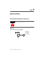
Applications/Wiring
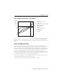
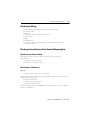
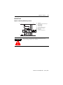
Control Circuit
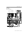
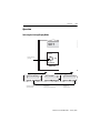
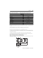
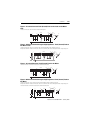
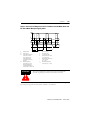
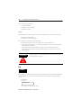
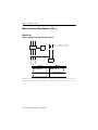
Figure 9.6 Control by Momentary Contact
F7
QM
QA
K1
F1
Us
L1
S0
S1
K1
QM
95
F1
97
MR
96
98
K1
825-M
24
A2
MR
AL
H3
#1
QM
A1
(L2/F8)
A1
23
#1
H2
QA
H3
S1
S0
Us
H1
H2
H1
A2
N
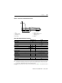
Circuit-breaker
Shunt trip coil
Contactor
Bulletin 825 Electronic control and protection
system
On push button
Off push button
Control voltage
Indicator “Contactor closed“
Indicator “825-M tripped” (except for
short-circuit protection
Main relay
Alarm relay
Indicator “Alarm/Warning“
Aux. relay, short-circuit indication
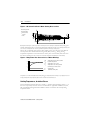
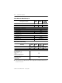
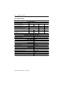
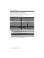
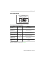
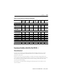
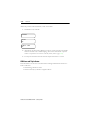
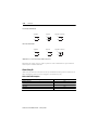
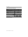
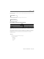
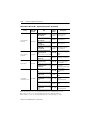
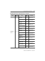
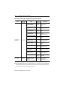
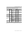
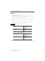
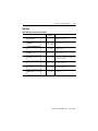
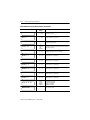
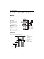
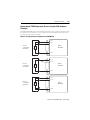
Two-Speed Motors
7KHIROORZLQJUDQJHVDUHSRVVLEOHIRUVSHHGV,DQG,,
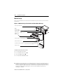
Speed I-II
0.5…2.5 A
2.5…20 A
20…180 A
with
with
with
160…630 A
with
Publication 825-UM001B-EN-P January 2001
Converter Module
825-MCM2
825-MCM20
825-MCM180
825-MCM630 or
825-MCM630N