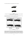
1
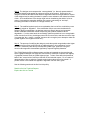
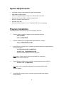
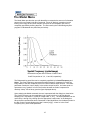
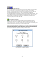
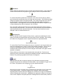
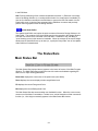
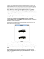
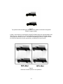
FHWA Design-by-Blur
Symbol Sign Optimization Software
User’s Manual
and
Tutorial Introduction
Version 1.0
December 1997
Contents
Introduction: Recursive-Blur Optimization of Symbol Sign Legibility ................ 3
Using the Recursive-Blur Technique ...................................................... 3
System Requirements ..................................................................................... 5
Program Installation......................................................................................... 5
Starting the Design-by-Blur Program ............................................................... 7
The Main Program Window ............................................................................. 7
The Menu Commands ..................................................................................... 9
File Menu ............................................................................................. 9
Edit Menu............................................................................................ 10
View Menu .......................................................................................... 12
Model Menu ........................................................................................ 15
Help Menu........................................................................................... 16
The Graphics Toolbox .................................................................................... 17
Area Select Tool ................................................................................... 17
Circle .................................................................................................... 17
Eraser ................................................................................................... 18
Filled Circle ........................................................................................... 18
Filled Rectangle .................................................................................... 19
Filled Round Box................................................................................... 19
Line....................................................................................................... 19
Line Width Selection ............................................................................. 20
New Sign Border Templates.................................................................. 20
Paint Brush ........................................................................................... 21
Paint Flood Fill ...................................................................................... 21
Polygon................................................................................................. 21
Rectangle.............................................................................................. 22
Round Box ............................................................................................ 22
Text ...................................................................................................... 22
Undo Buffer Update .............................................................................. 23
The Status Bars.............................................................................................. 23
Main Status Bar................................................................................... 23
Mouse Position Indicator ..................................................................... 24
Using the Blur Control Console....................................................................... 24
Importing Graphics Files................................................................................. 25
Know Bugs/Problems...................................................................................... 26
Appendix A: Tutorial Introduction to the Recursive-Blur Technique................. 27
Appendix B: Technical Reports....................................................................... 36
2
Introduction
Recursive-Blur Optimization of Symbol Sign Legibility
Unlike text signs that are composed of a finite set of alphanumeric elements (i.e., 26 letters
and 10 digits), symbol signs can assume countless shapes and permutations. As a result,
specific rules and guidelines for optimizing their legibility have proved to be elusive. It has
been proposed that much of the variability in the legibility of symbol highway signs could be
accounted for by the degree to which these signs depend upon high spatial frequency
contours to convey critical information (i.e., the greater the dependence upon high spatial
frequencies, the worse the legibility distance).
Recently, two corollaries of this model have been confirmed: (1) Schieber, Kline and Dewar
(1994) demonstrated that a symbol sign's legibility distance was related to its blur
recognition threshold; and (2) Dewar, Kline, Schieber and Swanson (1994) demonstrated
that a symbol sign's legibility distance could be improved by increasing its resistance to blur
degradation through a recursive, computer-assisted design processes (which they termed
the "recursive-blur" technique).
The "recursive-blur" technique represents a strategy for shifting critical information from
higher to lower spatial frequencies. Graphic images submitted to the technique should be
legible at greater viewing distances.
Using the Recursive-Blur Technique
As suggested above, symbol signs that convey critical information via low spatial
frequencies (large/broad/gradual contours) are legible from greater distances than symbol
signs that rely upon high spatial frequencies (fine detail). It follows, therefore, that the
relative legibility distance of a given graphical symbol can be quickly assessed by blurring it
until the observer can no longer recognize one or more of its critical details. For example, a
graphical symbol containing critical features that become unrecognizable at 40% blur
(simulated loss of visual acuity down to the 20/60 level) will tend to yield a legibility distance
that is significantly diminished relative to a symbol that is still clearly recognizable at the
50% blur level (20/70 simulated visual acuity).
The recursive-blur technique provides the designer of symbol signs with a development tool
that leverages this relationship between legibility distance and a symbol sign’s resistance to
blur degradation. In practice, application of the recursive-blur technique proceeds as
follows:
Step 1. First, the designer constructs a symbol to represent the message to be conveyed to
the observer. For best results, the black-on-white color format should always be used.
Step 2. Next, the designer uses a software tool to “blur” the graphical symbol under
investigation. The initial blur level is usually set to 40 or 50 percent.
Step 3. The designer evaluates the effect of the blurring operation upon the graphical
symbol. If the designer’s ability to easily recognize critical details in the symbol has not
been diminished by the blur operation, the designer gradually increases the level of blur
(usually in 10% increments) until his/her ability to recognize the symbol has been
compromised.
3
Step 4. The designer next compares the “unrecognizable” (i.e. blurred) representation of
the symbol side-by-side against the unblurred version of the symbol. At this point, the
designer scrutinizes the features that became degraded under blur and generates a revision
of the design aimed at making the detail in question more resistant to the deleterious effects
of blur. Such modifications in the design might include: broadening the width of a line or
contour, increasing the separation between two contours, enhancing an “end stop”,
increasing the radius of curvature of a design element, etc.
Step 5. The modified symbols are then re-evaluated at the level of blur at which they were
previously judged as “degraded”. If the modification fails to overcome the deleterious
effects of the blur manipulation, the designer returns to Step 4 (above) and generates
another candidate modification aimed at improving the symbol’s resistance to blur
degradation. If, on the other hand, the new design yields a symbol that is now recognizable
at the criterion level of blur, the designer saves the current revision and then returns to Step
3 to repeat the “blur - modify - evaluate” sequence all over again (In an attempt to make the
symbol legible at ever higher levels of blur).
Step 6. The process of modifying the design to make the symbol recognizable under higher
and higher levels of blur continues until no additional gains in “blur resistance” can be
identified. Research (cited above) indicates that symbol signs “optimized” using this
recursive-blue approach demonstrate significantly improved legibility distances.
The FHWA Design-by-Blur software system provides an integrated environment through
which a graphics designer can apply the "recursive-blur" technique to optimize the legibility
of graphical elements such as symbol highway signs. To learn more about the theoretical
basis of the "recursive-blur" technique read the on-line technical reports. For a "hands on"
demonstration of how to optimize a sample symbol sign explore the on-line tutorial. A
printed version of the tutorial also appears in Appendix A of this user’s guide.
See the following sections in the On-Line Help utility:
Read the On-Line Technical Reports
Explore the On-Line Tutorial
4
System Requirements
•
A personal computer using a 80386 or higher microprocessor
•
8 MB RAM (16 MB preferred)
•
SVGA color graphics adapter configured to 640x480 256-color mode
•
Hard disk with at least 5 MB of available storage space
•
Mouse or equivalent pointing device
•
MS-DOS 3.3 or later
•
Microsoft Windows version 3.1 or 3.11 (Windows 95/NT not yet supported)
Program Installation
Manual installation of the software can be accomplished as follows:
1.
Create a directory to hold the program and its associated help files:
mkdir C:\FHWA
mkdir C:\FHWA\BLUR
2.
Create a subdirectory to hold the sample clipart collection of images:
mkdir C:\FHWA\BLUR\CLIPART
3.
Insert DISK #1 into floppy drive A: and then copy the program and its support libraries
on to the hard drive:
A:\COPY BLUR16.EXE C:\FHWA\BLUR
A:\COPY *.DLL C:\WINDOWS\SYSTEM
(assumes standard Windows directory structure)
Note: Steps 1-3 above can be executed automatically by running the
INSTALL.BAT script on DISK #1.
4.
Insert DISK #2 into floppy drive A: and then copy the help files to the hard drive:
A:\COPY *.HLP C:\FHWA\BLUR
Note: Step 4 can be executed automatically by running the INSTALL.BAT
script on DISK #2.
5.
Insert DISK #3 into floppy drive A: and then copy the sample clipart images
to the hard drive:
5
A:\COPY *.BMP C:\FHWA\BLUR\CLIPART
Note: Step 5 can be executed automatically by running the INSTALL.BAT
script on DISK #3.
6.
Start up Windows 3.x.
7.
Attach the Design-by-Blur program to a Windows Program Group (e.g., Applications)
by following the steps listed below:
a. Open the Program Group by double-clicking its icon.
b. Select the New... command from the Program Manager’s File Menu.
Click the Program Item button and OK in the resulting dialog box.
c. Fill out the Program Item Properties dialog box as follows:
Description:
FHWA Design-by-Blur
Command Line:
C:\FHWA\BLUR\BLUR16.EXE
Working Directory: C:\FHWA\BLUR
6
Starting the Design-by-Blur Program
The icon for the Design-by-Blur program will be located in the Program Group selected
during installation. To start the program, open up the Program Group to which it belongs
and double click on the Design-by-Blur program’s icon (shown below).
FHWA
Design-by-Blur
Program Icon
Upon loading and starting-up, the program displays the Main Window (shown below).
Examine this window closely and make sure you can identify its major user interface
components.
The Main Program Window
7
Main Program Window with
Sample Design and Blur Inspection Windows
A more elaborate example of the program’s graphical user interface is shown above. A new
Design Window (FIRE.BMP) was opened using the File Menu. The graphics symbol
displayed in the Design Window was manipulated using the software components depicted
in the Toolbox bar. The blur resistance of the symbol can be evaluated by viewing the Blur
Inspection Window (Blur #1) that was created by clicking upon the Blur Image button (in the
Blur Control Console).
This manual is organized according to the major user interface components found in the
Main Program Window. Each of the following components will be described in turn: The
elements of the Main Menu Bar, the graphics Toolbox and its operations, the Main Status
Bar, the Mouse Position Indicator and, finally, the use of the Blur Control Console.
8
The Menu Commands
The File Menu
Each of the commands in the File Menu are described in the paragraphs listed below:
New Design
Creates a new Design Window and prepares it for creating a new highway sign graphics
from scratch. The new Design Window is given the default name of UNTITLED. The
filename is displayed in the header of the Design Window
Open Design...
Provides the user with a standard Windows dialog box to search through the file system
then select a compatible graphics file and display it in a Design Window. Compatible
graphics file formats include: Windows Bit map (BMP), uncompressed Tagged Image File
Format (TIF) and Graphics Interchange Format (GIF). These formats provide graphics
interchange compatibility with a large number of PC and Macintosh applications programs.
Important: In order for the Design-by-Blur program to be able to read a graphics file its
suffix must be either ".BMP", ".GIF" or ".TIF".
Note: Graphics input files are presumed to be 256-color, 256x256 images which use the
FHWA Design-by-Blur color palette. Imported 256-color images are automatically
converted. However, 4-bit (16 color) and 24-bit (true color) images will be rejected by the
Open Design command.
See:
Importing Graphics Files
Save Active Window
Closes the currently active graphics display window. The Save As... dialog box will
automatically be summoned if the window being closed is a Design Window which has not
been previously saved or which has been altered since previously saved. Note: Blur
Inspection Windows will be closed without calling the Save As... dialog described above.
Important: In order for the Design-by-Blur program to be able to read a graphics file its
suffix must be either ".BMP", ".GIF" or ".TIF". Be sure to append the appropriate suffix
when saving your work.
Save Active Window As...
9
Same as the Save Active Window command described above except that the user is
always prompted with the Save As... dialog box. Important: In order for the Design-by-Blur
program to be able to read a graphics file its suffix must be either ".BMP", ".GIF" or ".TIF".
Be sure to append the appropriate suffix when saving your work.
Printer Setup...
Displays the standard Windows dialog box for selecting and configuring printers connected
to the system.
Print Active Window
Prints the contents of the currently active Design Window or Blur Inspection Window.
Exit
Closes all graphics windows in the Design-by-Blur work space and terminates the program.
The Edit Menu
Each of the commands in the Edit Menu are described in the paragraphs listed below:
Undo
Copies the contents of the Undo Buffer to the currently active Design Window. The Undo
command is typically used to correct drawing errors by restoring the graphics window to a
previous state. The Undo buffer is updated every time a new tool is selected from the
graphics Toolbox or whenever the user manually issues the Undo Buffer Update command
via the "keep Edits" button in the graphics Toolbox.
Copy Selection
The Copy Selection command is enabled whenever there is an area within the current
Design Window which has been selected via the Area Select tool. The Copy Selection tool
transfers the selected area to the Paste Buffer making a copy of it available for pasting to
the current or other Design Windows.
See:
Area Select tool
Cut Selection
The Cut Selection command is enabled whenever there is an area within the current Design
Window which has been selected via the Area Select tool. The Cut Selection tool transfers
the selected area to the Paste Buffer making a copy of it available for pasting to the current
10
or other Design Windows. After copying the contents to the Paste Buffer, the selected area
is "filled in" with the current Background Color.
See:
Area Select tool
Paste Selection
The Paste Selection command is activated whenever the Paste Buffer has been filled via
the Copy or Cut Selection commands (described above). The Paste Selection command is
used to copy the contents of the Paste Buffer to the currently active Design Window.
Upon issuing the Paste Selection command from the menu, the graphics cursor changes to
the form represented below:
Paste Selection Cursor
To Paste the contents of the Paste Buffer to the active window, move the Paste Selection
cursor while holding down the left mouse button. As long as the left mouse button is being
depressed, a rectangle of the same size as the contents of the Paste Buffer will be
displayed. When the placement rectangle reached the location at which you wish to place
the contents of the Paste Buffer, release the left mouse button.
Note: The Paste Selection command does NOT copy the contents of the standard Windows
Clipboard to the screen. To transfer graphics via the Windows Clipboard refer to the
"Export/Import Image To Clipboard" commands described below.
Export Image To Clipboard
Copies the entire contents of the 256x256 Design Window or Blur Inspection Window to the
standard Windows Clipboard (i.e., transfer buffer). Images exported to the Clipboard are
then available to other Windows applications or can be used to create new copies of a
Design Window in the Design-by-Blur program itself.
Import Image from Clipboard
This command is active only when the standard Windows Clipboard contains bit mapped
graphics data exported by another application or via the "Export Image To Clipboard"
command described above. Issuing this command creates a new Design Window which
contains the contents of the standard Windows Clipboard.
If the Windows Clipboard contains bit mapped graphics from a foreign application, the
Design-by-Blur program translates it to conform to the standard FHWA color palette. If the
imported image contains a color which is not in the FHWA color palette, then the color is
matched to the closest available color.
See:
Importing Graphics Files
Clear Active Window
Fills the active graphics window with the current Background Color.
11
The View Menu
Each of the commands in the View Menu are described in the paragraphs listed below:
Select Standard Color Pairs...
This command allows the user to simultaneously change the Foreground and Background
Colors of the currently active Design Window. Upon executing the "Select Standard Color
Pairs" command, the user is presented with a dialog box (shown below) that provides the
opportunity to select from among 8 standard Foreground/Background Color combinations
typically used on U.S. highway signs. The user selects the desired color pair by clicking the
appropriate "radio button" and then confirms that choice by clicking the "OK" button. The
dialog box can be closed without changing the colors by clicking the "Cancel" button. The
state of the current Foreground (FG) and Background (BG) Colors can be determined at any
time by viewing the FG and BG parameters displayed in the Main Status Bar.
Select Standard Color Pairs Dialog Box
12
Select Foreground Color...
This command allows the user to change the Foreground Color used by most of the Toolbox
graphics commands to one of 10 standard color values supported by the FHWA Design-byBlur program. Upon issuing the "Select Foreground Color" command, the user is presented
with a dialog box (see below) that contains the available color options. The user selects a
new Foreground Color by clicking the appropriate "radio button" and then confirms that
selection by clicking upon the "OK" button. The dialog box can be dismissed without taking
any action by clicking upon the "Cancel" button. The state of the current Foreground Color
can be determined at any time by viewing the FG parameter displayed in the Main Status
Bar.
Select Foreground Color Dialog Box
Select Background Color...
This command allows the user to change the Background Color used by several of the
Toolbox commands. Upon issuing the "Select Background Color" command, the user is
presented with a dialog box (similar to the example shown above) that contains the
available color options. The user selects a new Background Color by clicking the
appropriate "radio button" and then confirms that selection by clicking the "OK" button. The
dialog box can be dismissed without taking any action by clicking upon the "Cancel" button.
The state of the current Background Color can be determined at any time by viewing the BG
parameter displayed in the Main Status Bar.
Font Attributes...
The Font Attributes command allows the user to control the font of the characters output by
the Text tool. The user is presented with the standard Windows dialog box (see below)
used to select text characteristics, including: Font (typeface), Style, Size and Color. It is
important to note that the Text tool uses the color specified via the Font Attributes box
rather than the Design Window's current Foreground or Background Colors. The options
available via the Font Attributes dialog box will vary according to the configuration of the
Windows environment in which the Design-by-Blur application is running. For more
information about the standard Font Attributes dialog box consult your Microsoft Windows
documentation package.
13
Font Attributes Dialog Box
Normal
This command removes any Zoom magnification from the active Design Window and
returns it to the Normal (1X) magnification mode of viewing.
Zoom 2X
This command changes the viewing mode for the active Design Window to a magnification
level of 2X (twice) the normal level of magnification. Upon entering Zoom magnification
mode, horizontal and vertical scroll bars are added to the Design Window. Use the Normal
command (described above) to remove Zoom magnification.
Zoom 4X
This command changes the viewing mode for the active Design Window to a magnification
level of four times (4X) the normal level of magnification. Upon entering Zoom
magnification mode, horizontal and vertical scroll bars are added to the Design Window.
Use the Normal command (described above) to remove Zoom magnification.
Zoom 8X
This command changes the viewing mode for the active Design Window to a magnification
level of eight times (8X) the normal mode of magnification. Upon entering Zoom
magnification mode, horizontal and vertical scroll bars are added to the Design Window.
Use the Normal command (described above) to remove Zoom magnification.
Image Info...
This command provides the user with a summary of the image attributes describing the
active Design Window (e.g., height, width, number of colors, image type). In addition, an
estimate of the amount of memory available in the Windows' global pool (including virtual
memory) is listed. This report is provided primarily for diagnostic purposes.
14
The Model Menu
The Model Menu provides the user with the ability to customize the amount of information
removed from an image by the Blur Command. Since all "blurring" operations involve
filtering of an image in the Fourier domain, the nature of the information loss can be
completely specified by defining that filter. The filter used by the FHWA Design-by-Blur
program is a Butterworth low pass filter (see below):
Butterworth low pass filter functions of Order=3 and
Cutoff Frequencies of 3, 6, 11 and 20, respectively
The Butterworth low pass filter can be completely specified by its Cutoff Frequency and
Order. The Cutoff Frequency represents the spatial frequency (expressed in cycles per
image width) of the 50% amplitude point on the filter's relative output function. The Order
parameter controls the "rate of decay" in the relative output function. An Order equal to 1
represents a very "gradual" roll off in the function whereas an Order=3 represents a
relatively "sharp" rate of decay (see the figure displayed above).
Upon selecting the Model command, the user is presented with the dialog box show below.
The Cutoff Frequency can be manipulated (via a scroll bar) from 1 to 80 (the Nyquist
sampling limit - expressed in cycles per image width - is 127). The Order parameter can be
varied from 1 through 3 by clicking upon the appropriate "radio button" in the dialog box.
When the Blur command has been customized via the Model Menu, the feedback window in
the Blur Control Console displays the label "custom [xx][y]" - where xx is the Cutoff
Frequency and y is the Order parameter.
15
Model Menu's dialog box.
The Help Menu
Each of the commands in the Help Menu are described in the paragraphs listed below:
Contents
Accesses the Main Table of Contents page used to navigate the FHWA Design-by-Blur OnLine Help system.
Search for Help On...
Accesses the Keyword and Topics Index of the FHWA Design-by-Blur Help file.
How to Use Help
Accesses the built-in tutorial on how to use the Window's Help system.
Design-by-Blur Tutorial
Transfers control to a brief on-line tutorial which explores the use of the Recursive-Blur
Technique for the optimization of graphics symbol legibility.
Technical Reports
This topic provides the user with the opportunity to access several published reports which
document the technical principles underlying the recursive-blur optimization of symbol sign
legibility.
About...
Displays software title, copyright and version information.
16
The Graphics Toolbox
The graphics Toolbox is a row of icons located just below the Menu Bar on the Main
Program Window. The Toolbox icons allow the user to quickly select a variety of tools for
drawing or modifying graphics displayed in a Design Window.
The Graphics Toolbox
Each of the operators accessible via the Toolbox is discussed in the paragraphs that follow:
Area Select
This tool is used to select an arbitrary rectangular region of the Design Window which is to
be subsequently operated upon by either the Copy Selection or the Cut Selection
commands in the Edit Menu. Upon clicking the Area Select icon in the Toolbox, the
graphics cursor changes to the form represented below:
Area Select Cursor
The Area Select tool's cursor resembles a pair of scissors since it is typically used as the
first step in common graphics "Cut and Paste" operations. To use the Area Select tool,
position the "cross hairs" of the cursor at the origin of the imaginary rectangular area that
you wish to select. Then, holding the left mouse button down, "drag" the cursor to the
opposite corner of the imaginary rectangle delineating the to-be-selected area. Upon
releasing the left mouse button, the selection is completed. [Note: The selected area is
marked by a rectangle composed of finely dotted lines. This temporary marking remains in
place until another area is selected or until another graphics operation is executed.] The
area within the selected region is now ready to be copied to the paste buffer using either the
Copy Selection or the Cut Selection commands.
Circle
This tool is used to construct a circle/ellipse in the active Design Window. Upon clicking the
Circle icon in the Toolbox, the graphics cursor changes to the form represented below:
Circle Cursor
The circle tool works by having the user layout an imaginary rectangle and then drawing an
ellipse which fits precisely within that imaginary rectangle (When the height and width of
17
that rectangle are equal the resulting ellipse is a circle). To use the Circle tool, position the
"cross hairs" of the cursor over the origin of the imaginary rectangle that will define the
resulting ellipse, then hold down the left mouse button and "drag" the cursor to form the
opposite corner of the imaginary rectangle. Upon releasing the left mouse button, the "best
fit" circle/ellipse is drawn within the Design Window. Like most Toolbox graphics
operations, the Circle tool draws using the current Foreground Color and Brush Size (Line
Width) settings.
Hint: Since exact positioning of objects drawn with the Circle tool is difficult, it is best to
layout circular objects at the beginning of the drawing process.
Eraser
Used to erase the underlying area of the active Design Window to the currently selected
Background Color. Upon clicking the Toolbox's Eraser icon, the graphics cursor changes to
the form represented below:
Eraser Cursor
To use the Eraser tool, position the active area of the Eraser cursor (the black box at the
upper left corner) over the area you wish to erase, hold down the left mouse button and
"drag" the mouse slowly. The current Background Color (BG) used by the Eraser tool can
be ascertained by examining the BG field in the Main Status Bar while the window of
interest is active (Note: Each active Design Window has an independently assigned
Foreground and Background Color). The Background Color can be changed via the Select
Background Color (Alt+B) and Select Standard Color Pairs (Alt+C) commands in the View
Menu.
Hint
The size of the Eraser is fixed at 8x8 pixels. If you need to do some erasing requiring a
more "refined" tool, try the following: Set the Foreground Color equal to the Background
Color and use the Paint Brush tool as an eraser. The Paint Brush tool can be resized to a
1x1, 2x2 or 4x4 pixel area using the Line Width Selection tool.
Filled Circle
Like the Circle operator, the Filled Circle tool allows the user to construct circles and ellipses
of arbitrary size in the active Design Window. However, in the case of the Filled Circle tool,
the interior area of the resulting graphics object is "filled in" with the currently selected
Foreground Color. Upon clicking the Filled Circle icon in the Toolbox, the graphics cursor
changes to the form represented below:
Filled Circle Cursor
Operation of the Filled Circle tool is identical to that described for the Circle tool.
See:
Circle tool
18
Filled Rectangle
Like the Rectangle operator, the Filled Rectangle tool allows the user to construct
rectangles of arbitrary size in the active Design Window. However, in the case of the Filled
Rectangle tool, the interior area of the resulting graphics object is "filled in" with the
currently selected Foreground Color. Upon clicking the Filled Rectangle icon in the
Toolbox, the graphics cursor changes to the form represented below:
Filled Rectangle Cursor
Operation of the Filled Rectangle tool is identical to that described for the Rectangle tool.
See:
Rectangle tool
Filled Round Box
Like the Round Box operator, the Filled Round Box tool allows the user to construct
rectangles with slightly "rounded" corners. However, in the case of the Filled Round Box
tool, the interior area of the resulting graphics object is "filled in" with the currently selected
Foreground Color. Upon clicking the Filled Round Box icon in the Toolbox, the graphics
cursor changes to the form represented below:
Filled Round Box Cursor
Operation of the Filled Round Box tool is identical to that described for the Rectangle
drawing tool.
See:
Rectangle tool
Line
The Line tool is used to draw straight lines within the currently active Design Window. Upon
clicking the Toolbox's Line icon, the graphics cursor changes to the form represented below:
Line Drawing Tool Cursor
To use the Line tool, position the "cross hairs" of its cursor over the starting point of the
desired line segment, press the left mouse button and "drag" the mouse until the "cross
hairs" of the cursor reach the end-point of the desired line. The line drawing is finalized
when you release the left mouse button. Like most items in the Graphics toolbox, the Line
tool draws using the current Foreground Color and Brush Size (Both of which are displayed
via the FG and Brush fields, respectively, in the Main Status Bar).
19
Line Width Selection
The Line Width Selection tool (shown above) consists of four adjacent icons which enable
the user to select the size of the paint brush used by the various Toolbox graphics
operators. From the thinnest line icon on the left to the widest line icon on the right, the
user may select paint brush sizes of 1x1, 2x2, 4x4 and 8x8 pixels, respectively.
The Line Width Selection tool operates only upon the currently active Design Window. That
is, each Design Window has an independently configurable Brush Size. The current Line
Width Selection can be determined by referring to the Brush Size parameter which is
continuously displayed in the Main Status Bar.
New Sign Border Templates
This tool is used to fill the active Design Window with the current Background Color
followed by the construction of a highway sign's daytime conspicuity border using the
current Foreground Color. This tool is normally used at the beginning of a new drawing as it
completely overwrites the information in the active Design Window.
Upon clicking the New Sign Border Template icon in the Toolbox, the user is presented with
the dialog box depicted below. The user can then select one of six available highway sign
borders by clicking upon the appropriate "radio button". The choice is then either accepted
by clicking the "OK" button or rejected by clicking the "Cancel" button.
New Sign Border Templates Dialog Box
20
Paint Brush
Used to paint the underlying area of the currently active Design Window. Upon clicking the
Toolbox's Paint Brush icon, the graphics cursor changes to the form represented below:
Paint Brush Cursor
To use the Paint Brush, position the "cross hairs" of its cursor over the area you wish to
paint, hold the left mouse button down and "drag" the mouse slowly. The Paint Brush draws
using the Foreground Color of the active window. The current Foreground Color (FG) can
be ascertained by examining the FG field in the Main Status Bar while the window of
interest is active. The Foreground Color can be changed via the Select Foreground Color
or Select Standard Color Pairs commands in the View Menu.
The "cross hairs" mark the upper left corner of the square pixels which will be produced
while using the Paint Brush tool. The current size of the Paint Brush can be ascertained by
examining the Brush field in the Main Status Bar. The Size of the Paint Brush can be
changed via the Line Width Selection tool.
Paint Flood Fill
This tool used the current Foreground Color to fill (i.e., replace) any adjoining area of the
same color as the pixel selected when the Paint Flood Fill tool is activated. Upon clicking
its Toolbox icon, the graphics cursor is replaced with the form represented below:
Paint Flood Fill Cursor
To use the Paint Flood Fill tool, position the cursor's "cross hairs" over the pixel which is to
serve as the starting point, or "seed", for the flood fill painting operation. Clicking the left
mouse key immediately initiates the flood fill process. Since the flood fill process
sometimes takes several seconds, the cursor changes to the familiar "hour glass" until the
operation is complete.
Exact positioning of the cursor is very important when using this tool. Precise cursor
positioning can be achieved by monitoring the feedback provided via the Mouse Position
Indicator or by switching to graphics Zoom levels 2X through 8X.
Polygon
This tool allows the user to construct a polygon of any dimension using the currently
selected Foreground Color and Brush Size (Line Width). Upon clicking the Polygon icon in
the Toolbox, the graphics cursor changes to the form represented below:
Polygon Cursor
When the tool is active, a polygon can be constructed by moving the cursor's "cross hairs"
to the starting position. The first line segment of the polygon is then constructed by
depressing the left mouse button and "dragging" the cursor from its origin to its destination
and then releasing the mouse button. Subsequent line segments are drawn by moving the
cursor to their respective end points (WITHOUT holding down the mouse button) and then
21
clicking the left mouse button to construct the next line segment. The polygon is finished
when the user clicks upon the point of origin of the initial line segment - thus forming a
"closed" polygon object. [Note: The area within a polygon can be filled to a solid color by
using the Paint Flood Fill tool.]
Rectangle
This tool is used to draw rectangles of arbitrary size. Upon clicking the Rectangle icon in
the Toolbox, the graphics cursor changes to the form represented below:
Rectangle Cursor
To use the Rectangle tool, position the "cross hairs" of the cursor over the point in the
drawing window that you wish to serve as the rectangle's origin, hold down the left mouse
button and "drag" the cursor until it sweeps out the desired rectangular form. Upon
releasing the left mouse button the rectangle object is finalized on the screen. Like most
Toolbox graphics operations, the Rectangle tool uses the current Foreground Color and
Brush Size (Line Width) settings.
Round Box
The Round Box tool allows the user to construct rectangles with slightly "rounded" corners.
Upon clicking its icon in the Toolbox, the graphics cursor changes to the form represented
below:
Round Box Cursor
Operation of the Round Box tool is identical to that described for the Rectangle drawing
tool.
See:
Rectangle tool
Text
The Text tool enables the user to overlay graphics images with text entered from the
keyboard using the text font (typeface), size, style and color previously specified via the
Font command in the View Menu. Upon clicking the Toolbox's Text icon, the graphics
cursor changes to the form represented below:
Text Tool Cursor
To use the Text tool, the user must first position the cursor's "cross hairs" to the upper left
corner of the imaginary rectangle that will hold the text characters about to be entered. The
user then clicks the left mouse key to mark the imaginary text insertion point and then
begins typing characters from the keyboard.
The Text tool is quite primitive. It provides no position feedback via a cursor nor does it
support a "back space" key for corrections. Errors must be handled via the Undo command
22
in the Edit Menu.
Hint: Precise positioning of text is best accomplished as follows: 1) Enter text in an empty
area of the Design Window (or, in another blank window if no empty space is available), 2)
Use the Cut Selection command in the Edit Menu to remove the text and transfer it to the
Paste buffer, and, 3) Use the Paste command in the Edit Menu to restore and precisely
position the text graphics within the Design Window.
Update Undo Buffer
The Update Undo Buffer tool copies the entire contents of the active Design Window to its
Undo Buffer. The contents of the Undo Buffer can then be recopied to the Design Window
at a later time via the Undo command in the Edit Menu. Needless to say, the ability to
"undo" drawing errors in this manner is invaluable. When the contents of the active Design
Window and its Undo Buffer are up-to-date (i.e., equal) the "Keep Edits" icon of the Update
Undo Buffer tool is deactivated.
The Status Bars
Main Status Bar
The Main Status Bar (depicted above) appears in the lower left corner of the Main Program
Window. The Main Status Bar provides the user with continuous feedback regarding the
status of four major drawing parameters:
Brush Size displays the current size of the paint brush (Line Width).
Zoom displays the current display window magnification level.
FG displays the current Foreground Color.
BG displays the current Background Color.
The Main Status Bar also serves another user feedback function. When the cursor moves
across one of the Menu Commands or Toolbox icons, a brief description of that command's
function (i.e., Hint Help) momentarily appears in the Main Status Bar window.
23
Mouse Position Indicator
The Mouse Position Indicator is located at the lower right corner of the Main Program
Window. It provides the user with continuous feedback regarding the X,Y coordinates of the
mouse/cursor within a drawing window. In addition, the "color" of the pixel at the current
cursor coordinates is also reported in one of two ways:
The Color Palette Index indicates the pixel's relative position within the standard FHWA
256 color palette. For example, index 0 is BLACK while index 255 is WHITE.
The RGB Color Definition reports the pixel's color in terms of its (R)ed, (G)reen and (B)lue
components.
Using the Blur Control Console
The ability to optimize the legibility of symbols using the recursive-blur technique requires
that the end-user be able to subject candidate graphic designs to progressively increasing
levels of blur. The Blur Control Console, located in the lower left quadrant of the Main
Program Window, provides the user with the means to implement low pass image filtering
under variable degrees of blur.
The Blur Control Console
The amount of blur can be increased by clicking upon the UP ARROW in the Blur Control
Console. Similarly, the current blur setting can be decreased by clicking upon the console's
DOWN ARROW. The current blur setting of the console is displayed in a small text window
located between the UP and DOWN arrows (e.g., the sample Blur Control Console depicted
above shows the current blur setting to be "80 percent (20/100)"). The blur settings can be
varied from “10 percent (20/30)” (minimum) to “100 percent (20/800)” (maximum blur) in
10% increments.
In order to blur an image, an active Design Window must be present in the Main Program
Window. Clicking the console's Blur Image button causes the image in the active Design
Window to be blurred according to the current setting displayed in the Blur Control
Console's text window. Since this operation takes several seconds, the cursor changes to
an "hour glass" to signal a wait condition. When the blurring operation is completed, the
cursor returns to normal and a blurred copy of the image in the active Design Window is
displayed in a newly created Blur Inspection Window. The title bar of the new window
depicts the amount of blur in parentheses (e.g. (Blur = 80) ).
24
Hints
Make sure that your targeted Design Window is active before pressing the console's Blur
Image button. If a Blur Inspection Window is active, a "nagging" error message will appear
since the program will not allow you to blur a previously blurred image (Although there is a
"work around" to actually accomplish this objective).
Since the Blur Inspection Window is created in the upper right quadrant of the Main
Program Window it is usually convenient to work with the Design-by-Blur program with its
Main Window in the "maximized" state.
If a customized level of blur has been selected via the Model Menu, the text window in the
Blur Control Console will display a message similar to "custom [15][3]" - where the pair of
numbers represent the Cutoff Frequency and Order parameters, respectively, of the low
pass filter used to implement the blurring operation (see the documentation for the Model
Menu). The title bar of the Blur Inspection Window containing the results of such a
"customized" blur operation will echo these parameters as follows: (Blur: 15/3).
See:
Model Menu (description of Butterworth low pass filter parameters)
Console Blur Settings
The percent blur settings (10-100%) available via the Blur Control Console interface
correspond to the following Butterworth low pass filter specifications:
Percent Blur
Cutoff
Frequency
Order
Equivalent
Acuity
10
50
1
20/30
20
50
2
20/40
30
40
3
20/50
40
32
3
20/60
50
24
3
20/70
60
20
3
20/80
70
16
3
20/90
80
12
3
20/100
90
8
3
20/200
100
4
3
20/800
Importing Graphics Files
The Design-by-Blur program operates in 256-color mode using a customized color palette
designed to render blurred images using a 128 level gray scale.
Graphics files created by other applications can be "imported" into the Design-by-Blur
environment via the Open Design or Import Image from Clipboard commands.
However, it should be noted that this import capability is less than "robust" at present.
Images to be imported must meet the following criteria:
(1) The images must be in 256 color mode. True Color (24-bit) and 16-color (4-bit) images
are not supported.
25
(2) For graphics files: The file must be in either BMP, GIF or TIFF (uncompressed)
graphics file format. Important: The suffix of a file to be opened by the FHWA program
MUST be either ".BMP", ".GIF" or ".TIF".
(3) All sizes are supported. However, the Design-by-Blur software is difficult to use with
image sizes other than the standard 256 wide by 256 high format.
Suggestions for Importing Graphics
The Design-by-Blur package attempts to automatically match colors in the imported image
to the limited set of colors available in the FHWA custom color palette. This results in
matches that are sometimes less than adequate.
Immediately following the import of a foreign image, do the following to assure the best
results:
Use the Paint Flood Fill tool to convert the imported image to a 2-color only format. Set
the foreground of the image to the FHWA standard color "Black" and the background to the
FHWA standard color "White". Blurring operations performed upon non-FHWA standard
colors yield "undefined" results!
Check the image size using the Image Info command in the View menu. If the height
and/or width do not equal 256 you should "Cut and Paste" the desired part of the imported
image to a "new" Design Window to coerce it into 256 x 256 FHWA format.
Use the Save Design As command to save the newly imported and modified image to disk.
Reload the newly created image file using the Open Design command and inspect it to
determine if the automatic color conversion process was appropriately implemented.
Special Hint
An easy way to set up a relatively seamless interface between the Design-by-Blur program
and other graphics applications is to adopt the following strategy: (1) Create a new (blank)
image using the Design-by-Blur software, (2) Save the image to a graphics format
supported by the other application program, (3) Open the Design-by-Blur native file with the
other application program. The foreign application program will now "inherit" the size and
custom color palette from the FHWA Design-by-Blur program. Subsequent imports of work
performed upon this image should be relatively "seamless".
Known Bugs/Problems
Importing images created in Correl Draw’s BMP graphics file format can cause “strange
results” in the Design-by-Blur program’s rendering of color. This occurs due to poorly
managed “competition” for the limited range of colors represented in the active color lookup table. No “affordable” solution to this problem has been developed. Therefore, users
should avoid the BMP file format when transferring files to/from Correl Draw and, instead,
employ either the TIF of GIF graphics file formats.
For the most recent list of bugs, problems and/or “work arounds” consult:
http://www.usd.edu/~schieber/DesignByBlur.html
26
Appendix A
Tutorial Introduction
to the
Recursive-Blur Technique
27
Introduction to the Tutorial
This tutorial takes you through a step-by-step implementation of the Recursive-Blur
Technique for the optimization of symbol sign legibility using the FHWA Design-by-Blur
program. Before participating in the tutorial you may wish to examine the On-Line
Technical Reports which describe the theoretical basis of the Recursive-Blur Technique.
Step 1: The Original Symbol Sign
The first step in this tutorial on graphics optimization using the Design-by-Blur program is to
Open or Draw the to-be-optimized graphics symbol. Figure 1 shows a Design Window
which contains the Fire Station symbol sign from the Manual of Uniform traffic Controls and
Devices (MUTCD). This graphic was downloaded from an internet site and then imported
into the Design-by-Blur program using the Open Design command in the File Menu.
Figure 1.
The Fire Station sign from the MUTCD
Next, we perform an initial evaluation of the sign by blurring it at the 40% level. This is
accomplished by:
1 Clicking the appropriate ARROW button in the Blur Control Console until the "40 percent"
level is displayed in the console's text window. Then...
2 Clicking the Blur Image button in the Blur Control Console
The Blur Control Console
28
The result of this initial 40% blur operation is displayed in a new Blur Inspection Window.
An example of what this window might look like is depicted in Figure 2 below:
Figure 2.
Results of initial 40% blur operation.
Inspection of the results of the 40% blur operation reveals that the critical detail in the Fire
Station sign, namely, the ladder, is still clearly recognizable. Next, we submit the sign to
greater levels of blur to ascertain the point at which the ladder is no longer recognizable
(i.e., We search for the blur legibility limit of the sign). Figure 3 is a composite graphic
which shows what the Fire Station symbol looks like when subjected to 40, 50 and 60
percent blur, respectively:
Figure 3.
Results of the 40, 50 and 60 percent blur operations.
29
Inspection of the results of these sequential blur operations shows that recognition of the
ladder reaches the "border line" state under 50% blur and becomes clearly unrecognizable
at 60% blur. Thus, we will now focus upon ways in which we can change the design of the
ladder so that it will become recognizable at blur levels of 50% and above.
Step 2: First Attempt to Optimize the Symbol
In order to make pair-wise comparisons of our developing graphic design optimizations, it
helps to construct a Design Window which contains both the "before" and "after" versions of
the graphic symbol. This is accomplished by:
1 Selecting the symbol using the Area Select tool.
2 Using the Copy Selection command in the Edit Menu to copy the selected symbol to the
paste buffer.
3 Creating a new Design Window via the New Design command in the File Menu.
4 Using the Paste command in the Edit Menu to make copies of the symbol at both the top
and bottom of the new Design Window
An example of this new Design Window containing duplicate copies of the original Fire
Station sign is shown in Figure 4 below:
Figure 4.
Dual symbol Design Window facilitates side-by-side comparison.
Our first attempt to improve the design of the sign will focus upon increasing the separation
of the horizontal lines used to render the ladder (i.e., the vertical risers of the ladder).
Generally speaking, greater separation distance between graphic elements leads to symbols
that are more tolerant to blur; and, thus, more legible outside of the laboratory or design
studio.
We achieve this by using the Paint Brush and Eraser tools. Usually editing a graphic
symbol in this way is easier under the 2X or 4X Zoom magnification level. Our initial
attempt to modify the ladder by increasing the separation of its horizontal line segments is
depicted in Figure 5:
30
Figure 5.
Top symbol shows broadening the separation of the ladder's horizontal line segments
(Bottom: original symbol).
In Step 1 of this tutorial, we saw that the original Fire Station sign was unrecognizable at the
50% blur level. Let's see if our new and (hopefully) improved version of the sign makes it
more legible at the 50% blur level. The results of subjecting the stimuli in Figure 5 to both
the 50 and 60 percent blur levels, respectively, are depicted in Figure 6 below:
Figure 6.
Results of 50 and 60 percent blur operations.
31
Inspection of the output of the 50% blur operation clearly reveals that our first modification
of the ladder was a success! The ladder in the original symbol (bottom left of Figure 6) has
"border line" recognizability at best. However, the ladder is clearly recognizable in the 50%
blurred rendition of the modified symbol (top left of Figure 6). In fact, the "improved" ladder
design is almost recognizable at the 60% level of blur (top right of Figure 6).
The output of the 60% blur operation reveals that our newly configured ladder design tends
to "blend into" the body of the truck upon which it is mounted. This suggests that the new
ladder design might be improved even farther by changing its position relative to the body
of the truck. We'll explore this possibility next!
Step 3: Another Improvement
Inspired by the inspection of the output of the previous 60% blur operation, our next attempt
to improve upon the legibility of the Fire Station sign will focus upon increasing the
separation distance between the new ladder configuration and the body of the truck upon
which it is mounted.
Again, these modifications will be implemented using the Paint Brush and Eraser tools
under Zoom magnification levels 1X through 4X.
The results appear in the top of Figure 7. Note the increased size in the gap between the
ladder and the truck.
Figure 7.
Original symbol (bottom) versus latest improvement (top).
Again, note the increased size in the gap between the ladder and the truck body in the
symbol at the top of Figure 7. This increased separation gap should eliminate the tendency
of the ladder to "blend into" the body of the truck at the 60% blur level. Let's evaluate our
attempt to increase the sign's tolerance to blur by putting it to the test! Figure 8 shows the
results of submitting our latest design to both the 60 and 70 percent blur levels,
respectively.
32
Figure 8.
Results of the 60 and 70 percent blur operations.
Inspection of the top left symbol in Figure 8 above clearly shows that our latest modification
of the ladder resulted in a demonstrable improvement in its blur tolerance. The ladder no
longer tends to "blend into" the body of the truck. Instead, it is now clearly recognizable at
the 60% level of blur. It should be noted, however, that our latest improvement reaches
only "border line" levels of recognizability at the 70% blur level - our most rigorous test to
date.
Examination of the current design at the 70% blur level suggests that a final increment in
legibility might be achieved by lengthening the ladder and, perhaps more importantly,
increasing the separation between the rungs of the ladder. We'll put these hypotheses to
the test in the next step of the tutorial!
Step 4: A Final Improvement
Our last attempt to improve the blur tolerance (and, hence, the legibility) of the Fire Station
sign will involve lengthening the ladder a bit as well as increasing the spacing between the
rungs of the ladder.
As before, these changes will be implemented using the drawing operations available via
the graphics Toolkit and the command menus.
33
The resulting modification of the symbol appears at the top of Figure 9.
Figure 9.
New design characterized by longer ladder, wider horizontal lines and greater separation
between rungs (Bottom: original design).
In order to test the new version of the sign, we will submit it to blurring at both the 70 and
80 percent levels of filtering. The results are depicted in Figure 10:
Figure 10.
Results of 70 and 80 percent blur operations.
Inspection of the top left portion of Figure 10 reveals that our final modifications appear to
have been efficacious. For the first time, the ladder is recognizable at the 70% blur level. It
should be noted, however, that the ability to recognize the symbol suffers considerably at
the 80% level of blur. One might suggest that we attempt one additional modification to the
ladder; namely, increase the separation between the rungs still more...Such a modification
34
would be ill-advised since it would begin to interfere with the "interpretation" of the element
as a ladder. This trade-off between improved legibility at the cost of decreased sign
comprehension is an important concern which must be carefully considered during symbol
sign optimization using the recursive-blur approach.
The final result of our tutorial symbol sign optimization appears in Figure 11. Now try the
process on your own and see if you can achieve similar (or even better) results.
Figure 11.
The final result of the sign optimization tutorial.
A thoughtful reading of the on-line Technical Reports is strongly recommended prior to
attempting the optimization process on your own!
Summary
Through a systematic application of the recursive-blur procedure we have managed to
improve the "blur tolerance" of a symbol highway sign from the 40% level all the way to the
70% level. This is a sizable increment in the "performance" characteristics of this graphics
symbol. Past research (see the link to the Technical Reports below) strongly suggests that
our engineered improvement in the blur tolerance of this sign will be accompanied by a
sizable increase in its legibility distance.
35