1
Evaluation Board User Guide
UG-016
EVALUATION BOARD HARDWARE
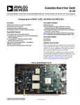
The evaluation board for the AD9276 and AD9277 provides all of
the support circuitry required to operate the AD9276 and
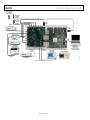
AD9277 in their various modes and configurations. Figure 2
shows the typical bench characterization setup used to evaluate
the performance of the AD9276 and AD9277. It is critical that
the signal sources used for the analog input and clock have very low
phase noise (<1 ps rms jitter) to realize the optimum performance
of the signal chain. Proper filtering of the analog input signal to
remove harmonics and lower the integrated or broadband noise at
the input is necessary to achieve the specified noise performance
(see the AD9276 or AD9277 data sheet).
See the Evaluation Board Software Quick Start Procedures
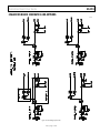
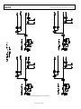
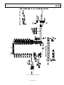
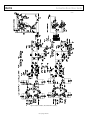
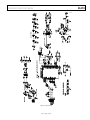
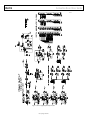
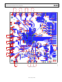
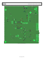
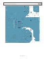
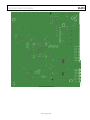
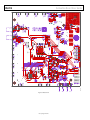
section to get started and Figure 21 to Figure 32 for the
complete schematics and layout diagrams that demonstrate the
routing and grounding techniques that should be applied at the
system level.
POWER SUPPLIES
This evaluation board comes with a wall-mountable switching
power supply that provides a 6 V, 2.5 A maximum output. Connect
the supply to the rated 100 V ac to 240 V ac wall outlet at 47 Hz
to 63 Hz. The other end is a 2.1 mm inner diameter jack that
connects to the PCB at P601. Once on the PC board, the 6 V
supply is fused and conditioned before connecting to low dropout
linear regulators that supply the proper bias to each of the various
sections on the board.
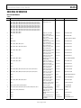
When operating the evaluation board in a nondefault condition,
L602, L603, L604, L605, L606, L607, L608, and L609 can be
removed to disconnect the switching power supply. This enables
the user to bias each section of the board individually. Use P602,
P603, and P606 to connect a different supply for each section. At
least one 1.8 V supply is needed with a 1 A current capability for
1.8 V AVDD and 1.8 V DRVDD; however, it is recommended that
separate supplies be used for both analog and digital domains.
An additional supply is also required to supply 3.0 V to the DUT,
3.0 V AVDD2. This should also have a 1 A current capability. To
operate the evaluation board using the SPI and alternate clock
options, a separate 3.3 V analog supply is needed in addition to
the other supplies. The 3.3 V supply, or 3.3 V AVDD, should have a
1 A current capability. To bias the CW I/Q demodulator section
and differential gain drive circuitry, separate +5 V and −5 V
supplies are required at P606. These should each have 1 A current
capability.
INPUT SIGNALS
When connecting the TGC (time gain compensation) ADC
clock, 4LO and analog source, use clean signal generators with
low phase noise, such as Rohde and Schwarz SMA or HP8644B
signal generators or the equivalent. Use a 1 meter shielded, RG-58,
50 Ω coaxial cable for making connections to the evaluation
board. Enter the desired frequency and amplitude (refer to the
specifications in the AD9276 or AD9277 data sheet). In the
default condition, the evaluation board is set up to clock the ADC
from the crystal oscillator, OSC501, when in the TGC mode.
If a different or external ADC clock source is desired, follow the
instructions in the Clock section. Typically, most Analog Devices,
Inc., evaluation boards can accept ~2.8 V p-p or 13 dBm sine
wave input for the clock. When connecting the analog input
source, it is recommended to use a multipole, narrow-band
band-pass filter with 50 Ω terminations. Analog Devices uses
TTE and K&L Microwave, Inc., band-pass filters. The filter
should be connected directly to the evaluation board.
OUTPUT SIGNALS
The default TGC setup uses the FIFO5 high speed, dual-channel
FIFO data capture board (HSC-ADC-EVALCZ). Two of the
eight TGC channels can then be evaluated at the same time. For
more information on channel settings on these boards and their
optional settings, visit http://www.analog.com/fifo.
The default I/Q demodulator setup uses two AD8021 amplifiers
for I-V conversion and two ADA4841 amplifiers for gain and
filtering. The analog outputs can be evaluated using an oscilloscope
or spectrum analyzer.
Rev. 0 | Page 3 of 28