1
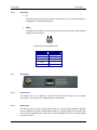
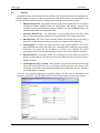
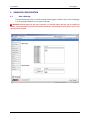
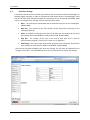
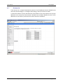
SmartPage‐E User Manual For v2.05 Unit Firmware (Manual Revision 1.02) Last updated 06/29/09 SmartPage‐E User Manual NOTICE This manual, software and electronic circuitry are copyrighted. All rights reserved. Under the copyright laws, this manual, software and electronic circuitry may not be copied, in whole or in part without written prior consent of JTECH Communications, Inc. (JTECH). All information provided in this document is carefully prepared and offered in good faith as a guide in the installation, use and servicing of our products. Installers must ensure that the final installation operates satisfactorily within the relevant regulatory requirements. JTECH accepts no responsibility for incorrect installation. JTECH reserves the right to change products, specifications, and installation data at any time, without notice. JTECH makes certain limited warranties with respect to defective diskettes, documentation and electronic circuitry. Please see the associated information contained on this page. SOFTWARE LICENSE STATEMENT This manual, software and electronic circuitry are protected by international copyright laws. Under the copyright laws, this manual, software and electronic circuitry may not be copied, in whole or in part without written prior consent of JTECH, except in the normal use of the software to make an archival copy of the software for the sole purpose of backing up the software and protecting your investment from loss or damage. LIMITED WARRANTY With respect to the physical documentation and physical electronic circuitry enclosed herein, JTECH warrants the same to be free of defects in materials and workmanship for a period of one year from the date of purchase. In the event of notification within the warranty period of defects in material or workmanship, JTECH will replace the defective diskettes, documentation and electronic circuitry. The remedy for breach of this warranty shall be limited to replacement and shall not encompass any other damages, including but not limited to loss of profit, and special, incidental, consequential, or other similar claims. JTECH specifically disclaims all other warranties, expressed or implied, including but not limited to implied warranties of merchantability and fitness for a particular purpose with respect to defects in the documentation and electronic circuitry, and the program license granted herein, in particular, and without limiting operation of the program license with respect to any particular application, use, or purpose. Page 2 © JTECH Communications, Inc. User Manual SmartPage‐E COMPLIANCE NOTICES SAA (AUSTRALIA) To ensure compliance with ACA Technical Standards, this equipment is labeled with a Telecommunications Compliance Label. For safety reasons, this equipment should only be connected to compliant telecommunications equipment in accordance with the manufacturer’s instructions. FCC (USA) Part 15 This equipment has been tested and found to comply with FCC Rules and Regulations, Part 15 with the limits of a Class B digital device, designed to provide reasonable protection against harmful interference. This equipment generates, uses and can radiate frequency energy and if not installed and used in accordance with the instructions, may cause interference harmful to radio communications. On the base of the equipment is a label containing an FCC Registration Number, if applicable. Part 90 This equipment has been tested and found to comply with FCC Rules and Regulations, Part 90. FCCID: T5GPT5 IC (INDUSTRY CANADA, INDUSTRIE CANADA) This class B digital apparatus complies with Canadian ICES‐003. IC: 4767A‐PT5 CE (EUROPE) JTECH declare under our sole responsibility that the product SmartPage‐E to which this declaration relates, is in conformity with the following standards and/or other normative documents. ‐ EN 300 224‐2 v1.1.1 (2001‐01) ‐ EN 55022: 1994 +A1: 1995 +A2: 1997 ‐ EN 301 489 ‐2 v1.3.1 (2002‐08) ‐ EN 60950‐1: 2001 We hereby declare that all essential radio test suites have been carried out and that the above named product is in compliance to all the essential requirements of Directive 1999/5/EC. The conformity assessment procedure referred to in Article 10(5) and detailed in Annex IV of Directive 1999/5/EC has been followed with the involvement of the following notified body: Bay Area Compliance Laboratory Corporation, 1274 Anvilwood Ave., Sunnyvale, CA 94089, USA Identification mark: 1313 (Notified Body Number) The equipment will also carry the class 2 equipment identifier (exclamation mark). The technical documentation relevant to the above equipment can be made available for inspection on application to JTECH. ROHS & WEEE To minimize the environmental impact and take more responsibility to the earth we live, JTECH hereby confirms that the following product series comply with Directive 2002/95/EC (RoHS) and 2002/96/EC (WEEE) of the European Parliament. © JTECH Communications, Inc. Page 3 SmartPage‐E User Manual SAFETY AND GENERAL INFORMATION Important information on safe and efficient operation. Read this information before using the unit. Exposure To Radio Frequency Energy Your SmartPage‐E contains a low power radio transmitter. When it is ON, it transmits radio frequency (RF) energy. Your SmartPage‐E is designed to comply with the following national and international standards and guidelines regarding exposure of human beings to radio frequency electromagnetic energy (EME): • United States Federal Communications Commission, Code of Regulations; 47 CFR part 2 sub‐part J • American National Standards Institute (ANSI) / Institute of Electrical and Electronic Engineers (IEEE) C95. 1‐1992 • Institute of Electrical and Electronic Engineers (IEEE) C95.1‐1999 Edition • National Council on Radiation Protection and Measurements (NCRP) of the United States, Report 86, 1986 • International Commission on Non‐Ionizing Radiation Protection (ICNIRP) 1998 • National Radiological Protection Board of the United Kingdom 1995 • Ministry of Health (Canada) Safety Code 6. Limits of Human Exposure to Radiofrequency Electromagnetic Fields in the Frequency Range from 3 kHz to 300 GHz, 1999 • Australian Communications Authority Radio communications (Electromagnetic Radiation‐Human Exposure) Standard 1999 The maximum power density for a VHF or UHF SmartPage‐E is 4.0 watts power output at a distance of 7.9 inches (20cm), calculated at 0.79mW / cm². The recommended minimum distance between the SmartPage‐E antenna and the human body or face is 12 inches (30cm). To assure optimal performance and make sure human exposure to radio frequency electromagnetic energy is within the guidelines set forth in the above standards, always adhere to the following procedures: Antenna Care Use only the supplied or an approved replacement antenna. Unauthorized antennas, modifications, or attachments could damage the device. Do NOT hold the antenna when the device is in use. Holding the antenna affects signal quality and may cause the SmartPage‐E to operate at a higher power level than needed. Do not use SmartPage‐E with a damaged antenna. If a damaged antenna comes into contact with your skin, a minor burn can result. The SmartPage‐E antenna port shall only be connected to internal antennas located with the same building as the main equipment. Electromagnetic Interference/Compatibility Nearly every electronic device is susceptible to electromagnetic interference (EMI) if inadequately shielded, designed, or otherwise configured for electromagnetic compatibility. SELV warning The TITAN SmartPage‐E and Alarm Router modules have been assessed as SELV throughout, all ports shall be connected to approved SELV circuits or an approved isolation unit shall be used. Potentially Explosive Atmospheres Do not operate the SmartPage‐E in any area with a potentially explosive atmosphere. Sparks in a potentially explosive atmosphere can cause an explosion or fire resulting in bodily injury or even death. Areas with potentially explosive atmospheres include fueling areas such as below decks on boats, fuel or chemical transfer or storage facilities, areas where the air contains chemicals or particles such as grain, dust, or metal powders, and any other area where you would normally be advised to turn off your vehicle engine. Areas with potentially explosive atmospheres are often but not always posted. Blasting Caps and Areas To avoid possible interference with blasting operations, do not use the SmartPage‐E near electrical blasting caps, in a blasting area, or in areas posted: “Turn off two‐way radio.” Obey all signs and instructions. Page 4 © JTECH Communications, Inc. User Manual SmartPage‐E Table of Contents 1 ABOUT THE TITAN SMARTPAGE‐E .................................................................................................... 7 1.1 Introduction ...........................................................................................................................7 1.1.1 Front Panel .......................................................................................................................... 9 1.1.2 LCD Display.......................................................................................................................... 9 1.1.3 LED Indicators...................................................................................................................... 9 1.1.4 Connectors ........................................................................................................................ 10 1.2 Rear Panel............................................................................................................................10 1.2.1 Antenna Port ..................................................................................................................... 10 1.2.2 Mains Input ....................................................................................................................... 10 2 INSTALLATION ............................................................................................................................... 11 2.1 Enclosure Mounting .............................................................................................................11 2.2 Antenna ...............................................................................................................................11 3 SOFTWARE CONFIGURATION ......................................................................................................... 12 3.1 Connecting ...........................................................................................................................12 3.2 Changing the Password ........................................................................................................14 3.3 Network Settings..................................................................................................................15 3.4 Protocol ...............................................................................................................................16 3.5 Pocsag..................................................................................................................................17 3.6 Site Survey ...........................................................................................................................18 4 ADVANCED CONFIGURATION......................................................................................................... 19 4.1 Send a Message....................................................................................................................19 4.2 Internal Pager Database .......................................................................................................20 4.3 Serial Port Settings ...............................................................................................................21 4.4 Transmitter Settings .............................................................................................................22 4.5 Status...................................................................................................................................23 4.6 Licensing ..............................................................................................................................24 4.7 IP Access List ........................................................................................................................25 5 TECHNICAL INFORMATION............................................................................................................. 26 5.1 Transmitters.........................................................................................................................26 5.1.1 The installation of Multiple Transmitters and Aerials....................................................... 26 5.1.2 VSWR................................................................................................................................. 26 5.2 Types of Antennas................................................................................................................27 6 APPENDIX ...................................................................................................................................... 28 6.1 Further Help and Support .....................................................................................................28 6.2 Technical Specifications........................................................................................................28 © JTECH Communications, Inc. Page 5 SmartPage‐E User Manual About This Handbook This manual is designed to assist with installation of the SmartPage‐E. Every component of the system is described in a separate section of the manual with step‐by‐step instructions to facilitate hardware installation and software configuration. Conventions NOTE: A note preceded with this symbol indicates secondary information pertaining to the topic under discussion. Æ IMPORTANT: A Right‐pointing arrow followed by text in this manner presents important information. ▲ WARNING: Warnings like this alert you to the fact that you might damage your equipment or lose data if you don't follow instructions carefully. Page 6 © JTECH Communications, Inc. User Manual 1 SmartPage‐E ABOUT THE TITAN SMARTPAGE‐E 1.1 Introduction The TITAN SmartPage‐E is a paging transmitter capable of encoding serial or TCP/IP data into POCSAG and then transmitting it to pagers via its inbuilt transmitter. SmartPage‐E includes both an Ethernet port and a serial port, which are used for system programming and data input from a myriad of third party systems. © JTECH Communications, Inc. Page 7 SmartPage‐E User Manual SmartPage‐E Kit Your TITAN SmartPage‐E Kit will contain: • SmartPage‐E Unit • IEC Mains power cable • Pack including 2 x rack ears, 6 x black countersunk screws, 4 x rubber feet • Communications cables o Green – Crossover serial cable (RJ45 to RJ45) o Black – Serial cable (RJ45 to DB9 female) o Blue – Straight through Ethernet cable (RJ45 to RJ45) o Red – Crossover Ethernet cable (RJ45 to RJ45) • This SmartPage‐E Installation Manual • CD containing manuals and configuration programs. If you have purchased the 5 watt version, you package will also contain: • Whip antenna • N‐type to BNC right angle adapter As part of the installation of your SmartPage‐E unit you may also require: • A PC with Ethernet capabilities and a browser installed, e.g. Internet Explorer. • A pager on the same frequency as the transmitter. • (25/50/100 watt version only) An antenna capable of handling the power from the amplifier. The type of antenna used must be carefully selected depending on the site and power output of the transmitter. See the Antenna Guide section later on in this manual for more information. Page 8 © JTECH Communications, Inc. User Manual 1.1.1 SmartPage‐E Front Panel 1.1.2 LCD Display NOTE: The LCD display is not available on the 5 watt SmartPage‐E version. The front panel contains a digital panel meter that displays the amount of current the power amp is drawing in real time ‐ it is therefore a useful diagnostic tool. The table below shows the nominal values that will be displayed when viewing each reading whilst the unit is transmitting a message. Model Number Amps 25 watt transmitter 5.0 – 8.0 50 watt transmitter 11.0 – 12.0 100 watt transmitter 17.0 – 19.5 1.1.3 LED Indicators • Power Indicator Power (Yellow) ‐ Indicates that power is applied to the back of the unit and that it is operational. • Ethernet Indicators IP Activity (Green) ‐ Indicates activity on the network IP Link (Green) ‐ Indicates device is successfully connected to the network. • RS232 Indicators TX (Red) ‐ Indicates transmit data activity on the RS232 port. RX (Green) ‐ Indicates receive data activity on the RS232 port. • Transmitter Indicators PTT (Yellow) ‐ Indicates that the externally connected POCSAG transmitter is currently busy transmitting (“Keyed up”) Data (Red) ‐ Indicates POCSAG data activity. Carrier Detect (Yellow) ‐ Indicates channel is busy. Also indicates the unit is initializing (may remain on for 30 secs if DHCP is used) © JTECH Communications, Inc. Page 9 SmartPage‐E 1.1.4 User Manual Connectors • IP The RJ45 Ethernet port may be used for connection to a PC or external system for configuration or operational purposes. • RS232 The RS232 port is used for connection to an external system. Details of the required RS232 pins are as follows: The pin‐outs are described below. Abbreviation GND RX TX CTS RTS Pin Number 4 5 6 7 8 1.2 Rear Panel 1.2.1 Antenna Port The antenna port is an opening to allow connection of the antenna to the internal transmitter. The connector is a standard female n‐type 50ohm. 1.2.2 Mains Input This IEC connector is used to supply power to the unit. You can plug 110‐240VAC 50/60Hz into here without the need to change power supplies or settings (input is auto‐sensed). You will have been supplied with a mains lead in the SmartPage‐E kit which will plug straight into this connector. Page 10 © JTECH Communications, Inc. User Manual 2 SmartPage‐E INSTALLATION By default a SmartPage‐E will wait for data from another system, such as the Master Controller, and transmit any messages it receives to pagers via its built transmitter. For further details on how to install and configure the SmartPage‐E and Master Controller, please refer to the Master Controller User Manual. 2.1 Enclosure Mounting Before mounting the enclosure, you will need to decide where to place the unit. The SmartPage‐E can be desk mounted or installed into a standard 19 inch rack frame. Your SmartPage‐E package contains four rubber feet which can be placed on the underside of the unit if you wish to desk mount it. If the unit is to be rack‐mounted, you will need to attach a pair of rack ears. Your SmartPage‐E package contains a set of rack ears and six screws. Use a Phillips screwdriver to attach the ears to the chassis. Use the supplied IEC mains power lead to connect 110‐240VAC 50/60 Hz supply to the unit. ▲ WARNING: SmartPage‐E 25/50/100 watt versions ‐ Do not cover any of the front, rear or top vents on the unit with objects or other equipment. If the transmitter is being rack mounted, ensure there is a gap of at least 2 rack‐units (4 inches / 10cm) above the top panel. This will ensure the transmitter has adequate ventilation. 2.2 Antenna A suitable antenna capable of handling the rated power continuously must be connected to the N‐type connector on the rear panel. 5 Watt Version ‐ The unit comes with a right angle adapter and whip antenna. However a different antenna may be installed for better coverage if required. 25/50/100 Watt Version ‐ The high power versions do not come with an antenna. A suitable antenna must be purchased separately depending on the coverage pattern, range and site requirements. The antenna and cable should have its VSWR checked before connecting the transmitter to it. See the Technical Information section later on for more information regarding antenna choice and VSWR. The antenna for the unit must not be mounted within 15 feet of any other sensitive electronic equipment including other TITAN products, routers, computers or phone systems. ▲ WARNING: The antenna must be placed at least 15 feet (5 meters) away from other electronic equipment to prevent interference. © JTECH Communications, Inc. Page 11 SmartPage‐E 3 User Manual SOFTWARE CONFIGURATION To configure SmartPage‐E, you will need a PC with a network card installed. 3.1 1. Connecting Using an RJ45 cable, connect the SmartPage‐E unit to the network (LAN). NOTE: If you do not have access to a Switch or LAN, you can connect the SmartPage‐E directly to a PC’s network card using a crossover Ethernet cable. The red cable supplied with your SmartPage‐E kit is a crossover Ethernet cable. 2. Make sure that the power is plugged into the SmartPage‐E unit. Check that the power LED is on and the busy LED has turned off after initializing. 3. Start Internet Explorer. It can generally be found from the Windows™ start menu by selecting Start ‐> Programs ‐> Internet Explorer. 4. Next we need to type the IP address of the SmartPage unit on the Address field of the Internet Explorer window. 5. If you have no DHCP server on the network, then the unit will default to 192.168.0.100. If you cannot connect to the unit, you should set your PC’s network card IP Address to be on the same subnet. For example if the SmartPage‐E is set to 192.168.0.100 you should manually set your PC’s IP Address to 192.168.0.x. (where x = 1‐255) 6. If you have a DHCP server on your network, then you can use the IPDiscover utility available on the CD that came with your SmartPage‐E to find the unit. When this utility is run, it will find any Ethernet based TITAN units on the local network and show the details for each. You can even remotely change the IP address and other network details on the fly. As you can see below, you can also view the serial number, firmware version, IP address, given name & the MAC address. Double click a unit in the list to connect and open up the web user interface. Page 12 © JTECH Communications, Inc. User Manual 7. SmartPage‐E When you have connected the unit, the Main Page will be shown. 8. Clicking on any of the Menu links in the left menu will bring up an authorization window like the one in the figure below. The default user name is “maint” with no password. ▲ WARNING: You should change this password as soon as possible for security reasons. 9. Once you have finished making changes in Internet Explorer, simply close the browser. NOTE: Click the User Guide menu to download and view the latest PDF manual for this product. © JTECH Communications, Inc. Page 13 SmartPage‐E 3.2 User Manual Changing the Password By default, a SmartPage‐E has no password set. The first thing you should do after connecting to the unit, is secure it with a password. To configure a password click the Password menu. The password can have a maximum length of 8 characters. Once you have entered a password the unit must be rebooted for the changes to take effect. Tick the Reboot box then click the Save button to confirm the changes. Page 14 © JTECH Communications, Inc. User Manual 3.3 SmartPage‐E Network Settings Next, it is a good idea to check that the Network settings of the unit are suitable. To configure these settings, click the Network Setup menu. • Hostname ‐ The hostname is a unique name that identifies a device on the network. This name will also be shown in the IPDiscover utility. • DHCP Enabled ‐ If a DHCP server exists on your network, it can provide the SmartPage‐E an IP address, mask and gateway automatically. Some DHCP servers allow the reservation of an IP address for a specified MAC address. If DHCP is not used (not ticked), the IP address, mask and gateway have to be manually configured. Please consult your IT administrator for these settings. • IP Address ‐ The IP Address of the SmartPage‐E unit when no DHCP server exists on the network. • Ethernet Protocol Port ‐ This is the TCP port that SmartPage‐E listens on for data from other systems (such as the Master Controller). • Mask ‐ The network mask determines what subnet an IP address belongs to. Normally this would just be set to 255.255.255.0 however certain networks may require a different setting. • Gateway ‐ If the device is to be accessed from the internet or another network, the gateway is the route used to reach the external network. This will normally be the IP address of the router on your network. • MAC ‐ This is the factory set unique hardware number on the network. Once you have finished configuring the network settings, the unit must be rebooted for the changes to take effect. Tick the Reboot box then click the Save button to confirm the changes. © JTECH Communications, Inc. Page 15 SmartPage‐E 3.4 User Manual Protocol A myriad of external devices and third party products can communicate with the SmartPage‐E to dispatch paging messages. In order to communicate with another device, the SmartPage‐E must first be told which protocol to use. To configure these settings, click the Protocol menu. • Ethernet Protocol Use ‐ The protocol that the Ethernet port (RJ45) will use. The options available are COMP1, COMP2, SCOPE, TAP, TNPP Duplex, TNPP Simplex, Terminal, Tekk and SMTP. If you are connecting to a Master Controller over the LAN/WAN/Internet, you would normally select the TAP protocol here. • Serial Port Protocol Use ‐ The SmartPage‐E can also accept RS232 data from other devices. Select the protocol needed here, or choose NONE if not using the serial port. • Max Msg Count ‐ This refers to the maximum number of messages that can be sent by a protocol in a single session/connection. A value of ‘0’ means no limit. (default 0) • Lookup PagerID ‐ If ticked, the system will look up the received address in its internal pager database and convert the Pager ID to a capcode before sending out the message. If unticked, the system will use the address it receives as the capcode. For further information, see the Internal Pager Database section in this manual. (default unticked) • Never Disconnect ‐ If this field is ticked, the SmartPage‐E will never disconnect from the device it is connected to. It will only end the session when the other device disconnects. (default unticked) • TAP Disable ID= every 2 seconds ‐ Some systems using the TAP protocol send carriage return (CR) control characters every 2 seconds to ensure that the other device is still responding. If this field is unticked the SmartPage‐E will respond with an “ID=” each time it is polled. (default unticked) Once you have finished configuring the protocol settings, the unit must be rebooted for the changes to take effect. Tick the Reboot box then click the Save button to confirm the changes. Page 16 © JTECH Communications, Inc. User Manual 3.5 SmartPage‐E Pocsag POCSAG is a protocol used to communicate with pagers. Some configuration may be required here, depending on the type of pagers being used and type of internal transmitter installed inside the SmartPage‐E. To configure these settings, click the Pocsag menu. • Speed ‐ The speed of transmission. This value must match that of the pagers receiving the messages. (default 512bps) • Default Tone ‐ Pagers can be programmed to emit different tones (beep codes) when a message is received. The default tone is “A” however this can be changed in this field. Some protocols such as SCOPE support multiple beep codes. • Type ‐ The type of message to send to the pager. Select between Tone only, Numeric or Alpha. This setting should match the type of the pager being used at the site. (default Alpha) • PTT / Data / Busy Invert ‐ These settings should normally be left at the default unless you are advised to change them by your place of purchase. If ticked, these invert the respective signal. (default PTT Invert ticked, Data Invert and Busy Invert not ticked) • Ignore Busy ‐ If ticked, the SmartPage‐E will send the message regardless of whether or not the channel is busy. By default this field will need to be ticked in order for messages to be transmitted. In order for channel busy detection to work (field unticked), a special transmitter module capable of detecting “channel busy” must be installed internally. Contact your place of purchase for further infomation. Once you have finished configuring the Pocsag settings, click the Save button to confirm the changes. © JTECH Communications, Inc. Page 17 SmartPage‐E 3.6 User Manual Site Survey This tool is often used to the test coverage area of a paging transmitter. This is accomplished by setting up the site survey function to send out a message to a pager every 15 seconds. You can now walk around the site with the pager and ensure that messages are received correctly in all areas. To conduct a site survey, click the Survey menu. • Capcode ‐ Enter the capcode of the test pager that you wish to use in the site survey. • Interval ‐ Enter the time between test messages sent out in seconds here. • Type ‐ Enter the encoding type used on the pager. Select between Alpha, Numeric or, Tone Only. • Survey Enable ‐ Tick this field and click the Save button to enable the site survey with the above settings. To stop the site survey at any time, untick this field and press the Save button again. • Transmitter Test Enable ‐ Tick this field and click the Save button to force the transmitter to send out a constant preamble signal. This is useful when testing the transmitter on an RF test set. To stop the transmitter test at any time, untick this field and press the Save button again. ▲ WARNING: The Transmitter Test function causes the transmitter to heat up rapidly. Do not use this test for extended periods of time as it may damage the transmitter. Page 18 © JTECH Communications, Inc. User Manual 4 SmartPage‐E ADVANCED CONFIGURATION 4.1 Send a Message The Send a Message menu is used to send out manual pages to either entries in the SmartPage‐ E’s internal pager database or to a specific cap code. ▲ WARNING: Manual paging in this menu structure is a licensed option and may not be enabled by default. If you would like to test that the systems transmitter is operating correctly, please use the site survey function instead. © JTECH Communications, Inc. Page 19 SmartPage‐E 4.2 User Manual Internal Pager Database The Pagers menu is used to edit SmartPage‐E’s internal pager database. The internal database can be used when manually sending messages from the SmartPage‐E web user interface (see Send a Message above) or when used in conjunction with Lookup Pager ID field discussed previously in this manual. If you are connecting to a Master Controller over the LAN/WAN/Internet, you would normally not need to configure this menu. Page 20 © JTECH Communications, Inc. User Manual 4.3 SmartPage‐E Serial Port Settings A myriad of external devices and third party products can communicate with the SmartPage‐E to dispatch paging messages. In order to communicate with another device, the SmartPage‐E must first be told some basic information about the connection such as data speed, bandwidth, baud rate etc. To configure these settings, click the Serial Port Setup menu. • Baud ‐ The transmission speed (baud rate) of the RS232 serial port on the SmartPage‐E. (default 9600) • Data bits ‐ The number of bits that actually contain information pertaining to the message. (default 8) • Parity ‐ A method of verifying the accuracy of the data sent and received on the serial port. Choose from either NONE (not used), ODD or EVEN. (default NONE) • Stop bits ‐ The number of bits sent at the end of each byte and is used for synchronization purposes. In this case it is either 1 or 2. (default 1) • Flow Control ‐ This refers to the “flow control” property of the connection. Choose from either NONE (not used), RTS/CTS, RS485 or XON/XOFF. (default NONE) Once you have finished configuring the serial port settings, the unit must be rebooted for the changes to take effect. Tick the Reboot box then click the Save button to confirm the changes. © JTECH Communications, Inc. Page 21 SmartPage‐E 4.4 User Manual Transmitter Settings To configure these settings, click the Transmitter Setup menu. ▲ WARNING: If this unit is a SmartPage‐E 25, 50, 100 watt transmitter, DO NOT adjust any of the settings on this screen without first contacting your place of purchase. Changing these settings may damage the Power Amplifier (PA) and it will not be covered under warranty. • Frequency Band ‐ After the SmartPage‐E unit has read the data from the internal transmitter, it will display the band of the radio inside. This will normally either be 148‐ 174MHz or 440‐470MHz. • Frequency ‐ Here you can type the frequency required for the site. For example if your pagers are operating on 450.325MHz, then you would type in 450325000. • Power Level ‐ Use the drop down menu to toggle between Low, Medium or High power levels. On the 5watt version, these values typically correspond to power output levels of 1W, 2W and 4W respectively. • Channel Spacing ‐ This field refers to the space between adjacent channels. In the majority of applications, 25kHz should be selected here (for ±4.5kHz FSK). If you are using pagers capable of narrow band (±2.5kHz FSK) you can select 12.5kHz in this field. Page 22 © JTECH Communications, Inc. User Manual 4.5 SmartPage‐E Status The status screen shows some useful statistics and diagnostic information for the SmartPage‐E unit. To view these details, click the Status menu. • Version ‐ Version of the firmware. • System Up Time ‐ Duration device has been turned on with rebooting. • Memory Available ‐ RAM that is available to store and send messages, and server web pages. • POCSAG Queued ‐ The number of messages that are queued, waiting to be sent. • POCSAG Sent ‐ The total number of messages sent since power on. • POCSAG Busy ‐ The total number of messages that have failed to send due to the channel being busy. • UART Status ‐ Indicates whether flow control is inhibiting transmit or receive of data. • PT5 Temperature ‐ Displays the current temperate of the internal transmitter. • PT5 Voltage ‐ Displays the voltage that is driving the internal transmitter. © JTECH Communications, Inc. Page 23 SmartPage‐E 4.6 User Manual Licensing Your system will normally come preconfigured with a license key. If you buy additional features or protocols, you will need to enter in a new license key. To view these details, click the Licensing menu. Once you have entered a new license key, click the Save button to confirm the changes. Page 24 © JTECH Communications, Inc. User Manual 4.7 SmartPage‐E IP Access List The IP Access List is a simple firewall which contains a list of IP addresses that are allowed to use and access the SmartPage‐E. To configure these settings, click the IP Access List menu. A received IP address is binary AND with each of the Masks. If the result matches one of the IP addresses in the control list, then the host is allowed. An IP of 0.0.0.0 disables the rule. If all IP addresses are set to 0.0.0.0, then the entire access control list is disabled. © JTECH Communications, Inc. Page 25 SmartPage‐E 5 User Manual TECHNICAL INFORMATION 5.1 Transmitters Thick steel and concrete, large magnetic and electric fields, and terrain and weather conditions will affect transmitter efficiency, so you will need to test the coverage of your local area transmitter at some stage during the installation. When you perform the test you should pay particular attention to the quality of the messages that you receive on the test pager. If you receive corrupted messages then it is possible that you will have problems sending messages to that region. If you find that you are receiving corrupted messages then you should consider the following methods for improving transmission quality: • • • • • • • 5.1.1 Move the antenna to a position that gives it a clear line of site to all areas you wish to cover. Reduce the length of the cable connecting the aerial to transmitter. Use the appropriate coaxial cable to connect the aerial to transmitter which will suit the length of the cable run. For example use RG213 for runs up to 20 meters and use LDF440 for runs over 20 meters. Choose another type of antenna for the transmitter. Position the antenna in a higher location or use an antenna with a higher gain. Increase the transmitter power. There are a number of objections to this method, such as local restrictions on aerial power. In addition, doubling the transmitter power to the aerial only gives an increase in range of a factor of 1:19 (fourth root). Mount the antenna on a different side of the tower. If the tower is large, the metal structure can affect the coverage pattern behind the tower. The installation of Multiple Transmitters and Aerials For buildings in an area with good field strength outside but weak reception within, possibly caused by shielding due to reinforcement in suspended slabs, metal plating and other building materials: • The supply lead to the aerial can serve as a radiator, effectively providing a 15 foot / 5 meter range from the cable. • The supply from open (leaky) coaxial cable as a line radiator lead to a 50 Ω terminator (the cable is in effect the aerial). 5.1.2 VSWR ▲ WARNING: VSWR is a measure of impedance mismatch between the transmission line and its load. The higher the VSWR, the greater the mismatch. A high VSWR means some of the transmitted signal is being reflected at the antenna, back down the coax line and back into the transmitter itself. If this value is too high, the amount of power reflected back into the transmitter can damage the transmitter. The minimum VSWR, i.e., that which corresponds to a perfect impedance match is 1. It is essential that the VSRW of the antenna and coax connected to the amplifier is set to 1.5 or better using a SWR meter. If this test is skipped, permanent damage may result to the amplifier. Damage will also occur to the unit if the amplifier is set to transmit if no antenna is connected to the unit. To transmit without an antenna connected to the unit, use a dummy load capable of handling at least the rated transmitter output power. Page 26 © JTECH Communications, Inc. User Manual 5.2 SmartPage‐E Types of Antennas Co‐linear (CL‐A‐VHF and CL‐A‐UHF) Co‐linear antennas are most suited for installations which require maximum range. The general coverage pattern for this type of antenna is shown below. (side view of site) Mopole (MO‐GIA‐VHF or MO‐GIA‐UHF) Mopole antennas are most suited for installations which require good building penetration and range. It is a good general purpose antenna. The general coverage pattern for this type of antenna is shown below. (side view of site) Side Mounted / Unity Gain Dipole (DIPOLE‐VHF or DIPOLE‐UHF) Dipole antennas are most suited for installations which require excellent building penetration. The general coverage pattern for this type of antenna is shown below. (side view of site) © JTECH Communications, Inc. Page 27 SmartPage‐E 6 User Manual APPENDIX 6.1 Further Help and Support Contact your Place of Purchase A JTECH Authorized Distributor or Dealer sets up most systems. Contact your place of purchase with inquiries beyond the scope of this manual. This Product is Not Field Serviceable Should a fault develop with the hardware or software, contact your place of purchase for the most appropriate form of action. Do not attempt to open or repair any of the products as this may void any warranty. 6.2 Technical Specifications Note: Specifications subject to change without any notice Equipment type .............................................................IP and serial based POCSAG encoder Ethernet Port ...............................................................................IEEE 802.3, 10 Base‐T, RJ45 Serial Port ................................................ RS232C, 300‐57600 Baud (default 9600bps), RJ45 RF Output Port............................................................................................... N‐type 50 Ohms Status LEDs ......................... Power, Busy, PTT, Data, RS232 Tx, RS232 Rx, IP Activity, IP Link Programming ................................................................ Via Web GUI using Internet Browser Internal Transmitter ........... 5 watt version ‐ 100mW to 5 watts adjustable (default 4 watts) ................25/50/100 watt version – 25, 50 or 100 Watts (± 10%) driven by 1‐4 Watt exciter Frequency range................................. VHF – 148‐174 MHz. UHF – 440‐470MHz Synthesized Channel Spacing .............................. 12.5 & 25 kHz spacing (5 and 6.25 kHz reference steps) Supported Protocols............................................................... POCSAG 512, 1200 or 2400bps ........................................ TAP (PET, IXO) / COMP1, 2 / SCOPE / Terminal / Tekk (Waveware) Pager Database............................................................................................... 1000 pager ID’s Power supply .............................................. 5 watt version – 110‐240VAC 50/60Hz 25W max ................................................... 25/50/100 watt version – 110‐240VAC 50/60Hz 350W max Dimensions ................................................. 5 watt version – 1RU standard 19 inch rack case ............................................. 17.3 x 8.1 x 1.7 inches / 439 x 205 x 44 mm (without rack ears) ..................................................... 25/50/100 watt version – 2RU standard 19 inch rack case .............................................. 19 x 16.5 x 3.4 inches / 439 x 430 x 88 mm (without rack ears) Weight ........................................................................................... 5 Watt unit – 5.9lb / 2.7kg ................................................................................................. 25 Watt unit – 15.4 lb / 7.0 kg ................................................................................................. 50 Watt unit – 21.0 lb / 9.5 kg ............................................................................................... 100 Watt unit – 21.0 lb / 9.5 kg Ambient temperature operating range......................0 – 50 °C (20‐90% RH non condensing) Storage temperature range.....................................‐10 – 60 °C (10‐95% RH non condensing) Page 28 © JTECH Communications, Inc.