1
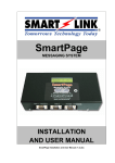
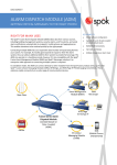
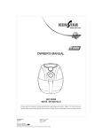
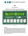
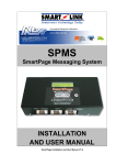
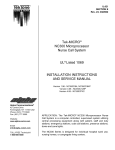
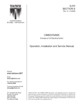
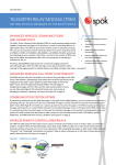
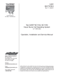
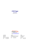
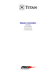
IL888 Section E NC369 Paging Transmitter Installation Instructions Rev. 7 - 06/2010 OVERVIEW EQUIPMENT APPLICATIONS TekTone ’s digital paging system can be used to transmit text and numeric messages directly to individual pocket pagers, or to entire groups of pagers. The NC369 Paging Transmitter includes both an RJ45 Ethernet port and an RJ45 RS232 serial port to accommodate system programming and Ethernet or serial input from TekTone® nurse call systems. Both ports can be used simultaneously and may be set to different protocols, allowing greater flexibility. It is the user’s responsibility to determine the suitability of this system for any given application. TekTone® cannot provide specific advice, since each application requires independent evaluation. TekTone® has no control of the use and application of the frequencies issued by the FCC. Some licensed equipment may have greater protection than other equipment operated on a FCC License Exempt basis. ® EQUIPMENT TESTING IMPORTANT SAFETY INFORMATION TekTone® products are designed to operate safely when installed and used according to general safety practices. The following requirements should be observed at all times. Do not subject this equipment to mechanical shock, excessive humidity or moisture, extremes of temperature, or corrosive liquids. • Do not operate this equipment with the antenna disconnected. Doing so may severely damage the transmitter. • This equipment is designed for indoor use only, unless expressly stated otherwise, and must not be used in classified Hazardous Areas, including areas containing explosive or flammable vapors, unless express authorization has been given in writing by the manufacturer. • Do not obstruct any slots or openings in the product. These are provided for ventilation to ensure reliable operation of the product and protect it from overheating. • Only use a damp cloth for cleaning (not liquid or aerosol based cleaners), and ensure that any power is removed from the unit prior to beginning the cleaning operation. • Removal of covers from the equipment must only be undertaken by authorized service personnel. SERVICE If your NC369 paging transmitter requires service, return it to TekTone® at the address listed below. Prior to returning the equipment, you must call TekTone®’s Sales Department at (800) 327-8466 and obtain a return authorization number (RMA number). No returns will be accepted without an RMA number. LIABILITY WARNING! TekTone does not accept any liability for any damage or injury howsoever resulting from misuse of this equipment. It is the responsibility of the user to ensure that the equipment is operated in the manner for which it was intended and that it is the correct item of equipment for the required task. Alteration or modification of any part of this equipment, without the prior written consent of the manufacturer, will invalidate all manufacturer Approvals and Warranties. No adjustments can be undertaken except by a qualified and licensed person as defined by the FCC Rules and Regulations. Operation of altered equipment can result in fines, imprisonment, and/or confiscation of such equipment. ® www.tektone.com 277 Industrial Park Road • Franklin, NC 28734 • [email protected] Phone: (828) 524-9967 • Fax: (828) 524-9968 • Tech Support: Choose option 2 • Sales: Choose option 3 TekTone®’s quality system is registered by UL® to the ISO 9001 standard. (Reference #10001510.) Copyright © TekTone Sound & Signal Mfg., Inc. All Rights Reserved. • Conduct range tests at least once a week; more often when critical criteria apply. This involves testing the unit past the limit of its required working range, so as to ensure a measure of safety. TekTone® suggests keeping a log of test dates and the information gathered, along with battery change data and service records. Required test frequency varies between applications. If a pager has been dropped or is worn by someone involved in an accident, test the unit again before reuse. The physical range tests are essential, and any construction work or movement of plant or equipment could alter the signaling capability of the unit. UNPACK THE EQUIPMENT INSTALL THE ANTENNA Carefully unwrap and inventory the pager transmitter and all components as shown below. If anything is missing, notify TekTone® immediately. An antenna capable of handling 5 watts must be connected to the BNC connector on the rear panel. The unit comes with a right angle adapter and whip antenna. However, a TekTone® CA133 mopole antenna may be installed for better coverage if required. The general coverage pattern for the CA133 antenna is shown in Figure 2. • • • • • IntelPage IP 5 Paging Transmitter. 12 VDC power supply with mains cable. Plastic wall mount bracket. Whip antenna with 90-degree adapter. Communications cables: 1. Green—Crossover serial cable (RJ45 to RJ45). 2. Black—Serial cable (DB9 female to RJ45, TekTone® part number CA134). 3. Blue—Straight through Ethernet cable (RJ45 to RJ45). 4. Red—Crossover Ethernet cable (RJ45 to RJ45). • This NC369 Installation Manual. • CD containing CommtechWireless Intelpage IP5 manuals and configuration programs. As part of the installation of your NC369 Paging Transmitter, you will also require: • A PC with terminal software installed (such as HyperTerminal), and/or • A PC with an Ethernet port and browser software installed (such as Internet Explorer). • A POCSAG receiver (pager) on the same frequency as the transmitter. The supplied CA134 black cable (serial DB9 to RJ45) is used to connect any TekTone® system that supports radio pocket paging. See Figure 1 for cable pinouts. The antenna for the unit must not be mounted within 16 feet (5 m) of any other sensitive electronic equipment including other paging system products, routers, computers or phone systems. Warning! Never transmit without an antenna attached to the transmitter. DETERMINE HARDWARE LOCATION Before mounting the NC369 Paging Transmitter, decide where to place the unit, considering the range of operation that the installation will require. The standard transmitter can quite easily provide ranges of up to one mile or more, and will provide excellent propagation on most industrial sites— covering a considerable area with just the supplied antenna connected directly to the unit. Thick steel and concrete, large magnetic and electric fields, terrain and weather conditions will affect transmitter efficiency, so test the coverage of your local area transmitter at some stage of installation. When performing the test, pay close attention to the quality of the messages received by the test pager. If the test pager receives corrupted messages, there may be problems sending messages to that region. For coverage of very large sites, or where exceptionally difficult operating conditions exist, it may be advantageous to install an external antenna (subject to license conditions). Contact TekTone® prior to any antenna change. Installing the Figure 1—Black Cable (Serial DB9 to RJ45) Pinouts Serial DB9 to RJ45 Interconnect Cable 5 4 DB9-F 2 1 8 7 6 NC369 Cable length must not exceed 50'. For longer distances, use PM368K Short Haul Modem Kit. 1 GND RX TX CTS RTS RJ45 3 9 8 IL888 NC369 Interconnect Cable Rev1 110609 1 Page 2 • IL888 NC369 Installation Instructions Copyright © TekTone Sound & Signal Mfg., Inc. All Rights Reserved. transmitter on the second or third floor of a building will usually boost overall range. However, horizontal range is not always required so much as propagation through a multistory building. Here it may be more useful to use a small external antenna mounted outside the building at half the building height. Sometimes range is required more in one direction than in another; moving the antenna to one side of the building can provide a bias in the required direction, which may overcome the range difficulties. When using a remote antenna, use a low-loss 50-ohm coax cable from the transmitter to the antenna. Do not use cabling for CCTV or TV satellite; this type of cable is normally 75 ohms. Important: Coaxial feeds over 16 feet (5 m) must employ low-loss 50ohm coax. We normally recommend feeds be no more than 50 feet (15 m) for standard applications. However, we suggest you contact our technical support department if other considerations prove this to be impractical. A further consideration is the distance between the transmitter and the source of the data feeding the transmitter. With a standard RS232 serial interface, data cables should not exceed 50 feet (15 m). The cables must be screened/ shielded and must be kept clear of sources of induced magnetic or electrical noise. If distances of over 50 feet (15 m) are required, additional drivers or amplifiers must be installed at both ends of the data link. Remember these important points when installing equipment: 1. Never install antennas near or adjacent to telephone, public address or data communication lines, or overhead power cables. 2. Avoid, wherever possible, running antenna coax alongside other cables. 3. Avoid mounting the transmitter in the immediate vicinity of telephone exchanges or computer equipment. 4. Remember that the performance of the system will be affected by the type of material the unit is mounted on and by its surroundings. 5. The circuit boards within this equipment may be harmed by Electrostatic Discharge (ESD). Installers must avoid touching the circuitry wherever possible, and must ensure that adequate antistatic procedures are adhered to at all times (earth grounding with wrist straps, etc.). This transmitter will be adversely affected by the following materials, if it is mounted on or near them: • • • • Foil-backed wall board Metal mesh, or wire-reinforced glass Metal sheeting, large mirrors or suspended ceilings Elevator shafts All of the above can reflect radio waves and thereby reduce the capability of the transmitter to perform its desired functions. 6. Warning! Never transmit without an antenna attached to the transmitter. MOUNT THE HARDWARE The NC369 Paging Transmitter comes default with rubber feet installed, allowing it to sit on a desk or table. The kit also includes a wall mounting bracket. To install this bracket: 1. Use a Philips screwdriver to remove the four screws holding the rubber feet. 2. Seat the bracket on the base of the unit. It will fit just one way. 3. Use the screws removed from the rubber feet to hold the wall mounting bracket in position. SOFTWARE CONFIGURATION The NC369 Pager Transmitter must be configured to work with your TekTone® nurse call or wireless emergency system. Two methods are available: Figure 2—CA133 Mopole Antenna Coverage Pattern 1. The preferred method, described in the following pages, requires a PC with a TCP/IP network connection, an internet browser (such as Internet Explorer), and an Ethernet connection to the NC369 Paging Transmitter. This method uses the enclosed red crossover RJ45 to RJ45 Ethernet cable to connect the PC to the NC369. 2. The alternate method requires a PC with a terminal program (such as HyperTerminal, included with Microsoft Windows®) and a serial connection to the unit using the enclosed CA134 black straight-through DB9 to RJ45 serial cable. To use this method, refer to Section 3.1 (pages 12– 24) of the Intelpage IP 5 installation manual on the included CD. Copyright © TekTone Sound & Signal Mfg., Inc. All Rights Reserved. IL888 NC369 Installation Instructions • Page 3 SET UP THE PC–NC369 NETWORK NC369 CONFIG TOOL SETTINGS As shipped, the NC369 Pager Transmitter will not work with your TekTone® nurse call or wireless emergency system— you must configure it. Use a PC that has an Ethernet port and a browser (such as Internet Explorer). Disconnect this PC from any other network. Using the Config Tool: • Clicking on one of the menu buttons on the left first brings up an authorization window. Type maint for the user name; leave the password blank. 1. Connect the power cord to the Power 12V DC jack on the back of the NC369, and then plug it into a wall outlet. Check that the power LED is on and the busy LED has turned off after initializing. 2. Connect one end of the red crossover Ethernet cable (RJ45 to RJ45) to the Ethernet port on the back of the NC369. Connect the other end to the PC’s Ethernet port. 3. Insert the Fusion Series CD included with your NC369 Pager Transmitter into the PC, and run the IPDiscover program in the Tools folder. The IPDiscover program will display the IP Address of your NC369 Pager Transmitter. Record your NC369 Pager Transmitter ’s IP Address here: • In the descriptions of the menu items below, items that must be changed to enable the NC369 Paging Transmitter to work with your TekTone® system are marked with an or (arrow), and new settings are shown in italics. • The SAVE button at the bottom of each menu page saves and commits the changes to that menu page. The UNDO button reverts all on-screen field values to those last saved. Clicking on a menu option without first clicking on the SAVE button has the same effect as clicking on the UNDO button. • When you have finished making the changes required and saving them, close the Internet Explorer window to exit the program. NC369’s IP Address:______._______. ______. ______ |––––––– SUBNET –––––––| HOST # | Home—Clicking this button returns you to the welcome page. 4. Set your PC’s IP Address to be on the same subnet as the NC369, but a different host number. (The first three groups of numbers are the subnet; the last group of numbers is the host number, and is between 0–255.) Send a Message—This feature is not available. Instead, use the site survey function to test that the NC369 is operating correctly. PC’s IP Address:______. ______. ______. ______ Subnet Mask: 255.255.255.0 Access the PC’s IP Address settings via Start | Settings | Control Panel | Network Connections. The prompts may vary, depending upon the version of Windows® used. Use the settings shown above to modify an existing network connection, or to create a new network connection (choose manual configuration when prompted). 5. Start Internet Explorer. It can usually be found via Start | Programs | Internet Explorer. 6. In the address field of the Internet Explorer window, type in the IP Address of the NC369 Paging Transmitter and press ENTER. This welcome screen will appear: Pagers—This screen is used to enable pagers in the NC369’s internal pager database. (Default is Enabled Alphanumeric for pagers 400– 499; all other pagers are Disabled). To enable a pager, click on its number and then the EDIT button. (For pagers used with the TekCARE®NC300II nurse call system, choose a pager between 400–447. For pagers used with the Tek-CARE®400 nurse call system or the TekCARE ® 500 wireless emergency call system, choose a pager between 000–999.) Type a TekTone® 5-digit Pager ID in the Capcode field. Use this formula to convert the desired 3-digit CAP code to its corresponding 5-digit Pager ID: Pager ID = [(pager’s CAP code × 8) + 10000] See Figure 3 for a CAP code to Pager ID conversion table for the CAP codes most commonly used with TekTone® pagers. Choose Alpha in the Type field, and then click on the SAVE button. Repeat to enable additional pagers. TekTone® recommends enabling extra pager numbers for future use to avoid reprogramming the NC369. Page 4 • IL888 NC369 Installation Instructions Copyright © TekTone Sound & Signal Mfg., Inc. All Rights Reserved. Network Settings—Normally these settings will not need to be changed; use the default settings. If changes are made to this menu page, check the REBOOT? box and then click on the SAVE button. Transmitter Settings—After all changes have been made to this menu page, click on the SAVE button. Serial Port Settings—After all changes have been made to this menu page, check the REBOOT? box and then click on the SAVE button. Frequency Band—After the NC369 Paging Transmitter has read the data from its internal transmitter, it will display the band of the radio inside. This is 440–470MHz, and cannot be changed. Baud—The transmission speed of the RS232 port (default 9600). Data bits—The number of bits that actually contain information pertaining to the message rather than to the transmission (default 8). Parity—A method of verifying the accuracy of the data sent (default NONE). Frequency—Type in the frequency required for the site. TekTone® pagers operate on 457.55 MHz, therefore, type in 457550000 Hz. Power Level—Use the drop down menu to toggle between Low (500mW), Medium (2W) or High (5W) power levels (default High). Select Medium (2W), the maximum allowed without a special FCC license. Channel Spacing—This field refers to the space between adjacent channels. Select 25kHz (for ±4.5kHz FSK). Stop bits—The number of bits sent at the end of each byte; used for synchronization purposes (default 1). Flow Control—This refers to the “flow control” property of the connection (default NONE). Set as follows: Tek-CARE®400 or Tek-CARE®500—RTS/CTS All other TekTone® systems—NONE Figure 3—CAP Code to Pager ID Conversion Table for the CAP codes most commonly used with TekTone® pagers CAP Pager Code ID 400 13200 401 13208 402 13216 403 13224 404 13232 405 13240 406 13248 407 13256 408 13264 409 13272 410 13280 411 13288 412 13296 413 13304 414 13312 CAP Pager Code ID 415 13320 416 13328 417 13336 418 13344 419 13352 420 13360 421 13368 422 13376 423 13384 424 13392 425 13400 426 13408 427 13416 428 13424 429 13432 CAP Pager Code ID 430 13440 431 13448 432 13456 433 13464 434 13472 435 13480 436 13488 437 13496 438 13504 439 13512 440 13520 441 13528 442 13536 443 13544 444 13552 Copyright © TekTone Sound & Signal Mfg., Inc. All Rights Reserved. CAP Pager Code ID 445 13560 446 13568 447 13576 448 13584 449 13592 450 13600 451 13608 452 13616 453 13624 454 13632 455 13640 456 13648 457 13656 458 13664 459 13672 CAP Pager Code ID 460 13680 461 13688 462 13696 463 13704 464 13712 465 13720 466 13728 467 13736 468 13744 469 13752 470 13760 471 13768 472 13776 473 13784 474 13792 CAP Pager Code ID 475 13800 476 13808 477 13816 478 13824 479 13832 480 13840 481 13848 482 13856 483 13864 484 13872 485 13880 486 13888 487 13896 488 13904 489 13912 CAP Pager Code ID 490 13920 491 13928 492 13936 493 13944 494 13952 495 13960 496 13968 497 13976 498 13984 499 13992 IL888 NC369 Installation Instructions • Page 5 Protocol—After all changes have been made to this menu page, check the REBOOT? box and then click on the SAVE button. Max Msg Count—The maximum number of messages that can be sent by a protocol in a single session/ connection. A value of “0” means no maximum limit (default 0). Lookup PagerID—If checked, the system will look up Pager IDs in the pager database. Otherwise the system will use the cap code supplied in the message (default OFF). Set the Lookup PagerID according to which TekTone® product it is used with: • Tek-CARE ® NC300II—Check this option, enabling it. • All other TekTone® systems—Leave unchecked, disabling it. Never Disconnect—If checked, the NC369 will never disconnect itself. It will only disconnect when the system it is connected to does (default OFF). TAP Disable ID= every 2 seconds—If left unchecked and the TAP protocol is being used, a carriage return resulting in an “ID=” will be issued every 2 seconds (default OFF). Ethernet Protocol Use—(Not used with TekTone® systems.) The protocol used by the Ethernet port (RJ45). All protocols use TCP port 6000 (this port is adjustable within the HTML interface) (default TAP). Serial Port Protocol Use—The protocol used by the RS232 port. Options available are: COMP1, COMP2, SCOPE, TAP, TNPP Duplex, TNPP Simplex, Terminal and Tekk. Notes: The password in the TAP protocol is ignored. Pager 0 must be configured for COMP1. If you are sending to a combination of numeric, alpha and tone pagers, you will need to use TNPP or SCOPE. The TNPP device address is 1234; TNPP received address is ignored—all messages are accepted. Email Domain—If SMTP is selected and an email is sent to <cap code>@<email domain>, the message will be encoded into POCSAG and transmitted to the pager with the corresponding cap code (default intelpage.mycompany.com). See 4.5 Setting up Email Paging on page 48 of the manual on CD for more information. Priority Keywords—Priority keywords allow a different beep code to be sent if a certain word is received in a message. For example, most messages may be sent through to users with the default beep code (tone) A. But for important messages containing, say the word “fire,” could be sent with beep code D. In this case, type “fire” in the Priority Keyword field, and select D in the Tone Replacement field. Set the Serial Port Protocol Use according to which TekTone® product it is used with: • NC375 Voltage Interface—SCOPE. • NC377 Paging Interface Adapter (Voltage Interface)—SCOPE. • Tek-CARE®NC300II—COMP2. (No escalation— pager tones and vibrate modes will not differentiate between call types.) • Tek-CARE®400 and Tek-CARE®500—SCOPE. Page 6 • IL888 NC369 Installation Instructions Copyright © TekTone Sound & Signal Mfg., Inc. All Rights Reserved. Pocsag—After all changes have been made to this menu page, click on the SAVE button. IP Access List—This is the list of IP addresses that are allowed to access the NC369 Paging Transmitter. Do not make changes to this list. Survey—This button is used to test a site by sending messages periodically. See the Site Survey section below for usage instructions. Status—The status screen shows some useful statistics about the NC369 Paging Transmitter. Version—Version of the firmware. System Up Time—Duration device has been on. Memory Available—RAM that is available to store and send messages, and server web pages. POCSAG Queued—The number of messages that are queued, waiting to be sent. POCSAG Sent—The total number of messages sent since power on. Speed—The speed of transmission. This value must match that of the pagers receiving the messages (default 512). Tek-CARE®400 and Tek-CARE®500 system settings must also match this value. • Select 512 baud for all TekTone® systems. POCSAG Busy—The total number of messages that have failed to send due to the channel being busy. UART Status—Indicates whether flow control is inhibiting transmit or receive of data. • Program all pagers to 512 baud. PT5 Temperature—Displays the current temperate of the internal transmitter. • Tek-CARE®400—Use the LS450 Config Tool to set speed to NORMAL, and then commit changes. PT5 Voltage—Displays the voltage that is driving the internal transmitter. • Tek-CARE®500—Use the LS500 Config Tool to set speed to NORMAL, and then commit changes. Default Tone—The type of tone that the pager will emit when the message is received (default A). Licensing—Not used with TekTone® systems. User Manual PDF—Requires an internet connection; refer instead to this manual and the Intelpage IP5 Installation Manual on CD. Type—The type of message to send: Tone only, Numeric or Alpha. This should match the type of the pager (default Numeric). Note: If the SCOPE protocol was chosen, then speed, tone and type are specified with the message and will override the POCSAG settings. Select Alpha. PTT / Data / Busy Invert—If checked, these invert the respective signal. Check PTT Invert, enabling it. Leave Data Invert and Busy Invert unchecked. Ignore Busy—If checked, send the message regardless of whether or not the channel is busy. WARNING: This must be checked in order for the transmitter to operate by default. Check this option, enabling it. Password—This is the password that must be entered in order to edit the Intelpage IP 5 settings. It has a maximum length of 8 characters (default: no password). If changes are made to the password, check the REBOOT? box and then click on the SAVE button. Copyright © TekTone Sound & Signal Mfg., Inc. All Rights Reserved. IL888 NC369 Installation Instructions • Page 7 SITE SURVEY CONNECT THE SYSTEM Click on the SURVEY button in the NC369 Config Tool to access the Site Survey screen. Use the supplied black cable (serial DB9 to RJ45) to connect the NC369 Pager Transmitter to your TekTone® nurse call system, wireless nurse call system, or voltage interface. Configure the connected TekTone® product according to instructions in its installation manual, and test to verify that both automatic and manual (if available) pages are received by pagers as expected. TECHNICAL SPECIFICATIONS Note: Specifications are subject to change without notice. This section is used to test a site by sending messages periodically. One person is required for a site survey. Once you have triggered the site survey, walk around the area intended to be covered by the transmitter, making particular note of the quality of messages received by the test pager. The Transmitters and Antennas sections below contain some useful tips on improving coverage and performance. Capcode—Type the TekTone® 5-digit Pager ID of the test pager that you wish to use in the site survey. (See Figure 3 to convert a CAP code into a Pager ID.) Interval—Enter the time between test messages sent out in seconds. Type—Enter the encoding type used on the pager. Select between Alpha, Numeric, Tone Only or Disabled. (Select Alpha.) Survey Enable—Check this option and click on the SAVE button to start the site survey using the above settings. When the survey is complete, uncheck this option and click on the SAVE button to stop the site survey. Transmitter Test Enable—Check this option to force the transmitter to send out a constant preamble signal. This is useful when testing the transmitter on a test set. WARNING: This test mode causes the transmitter to heat up rapidly. Do not use this test for extended periods of time as it may damage the transmitter. Page 8 • IL888 NC369 Installation Instructions Manufacturer: Equipment type: Ethernet Port: Serial Port: CommTechWireless IP and serial based POCSAG encoder IEEE 802.3, 10 Base-T, RJ45 RS232C, 300–57600 Baud (default 9600bps), RJ45 Signaling Level: Status LEDs: 0–5V CMOS Power, Busy, PTT, Data, RS232 Tx, RS232 Rx, IP Activity, IP Link Programming: Via Terminal or Internet Browser Internal Transmitter: Selectable for 500mW, 2W or 5W. (Facility must have an FCC license is to use a power level greater than 2W.) External antenna connector: Frequency range: BNC Female 50ohm VHF: 148–174 MHz. UHF: 440–470MHz Synthesized Supported Protocols: POCSAG 512, 1200 or 2400bps, TAP (PET, IXO) / COMP1, 2 / SCOPE / Terminal / Tekk (Waveware) Message capacity: Pager Database: Power supply: Dimensions: Weight: No capacity 1000 pager IDs 12VDC @ 2Amps regulated 10"×8"×2.7" (255mm×230mm ×70 mm) 700g / 1.5lb net Ambient temperature 0–50°C operating range: (20–90% RH non-condensing) Storage temperature range: -10–60°C (10–95% RH non-condensing) Copyright © TekTone Sound & Signal Mfg., Inc. All Rights Reserved.