1
(SAT As of August, 2012 No.2)
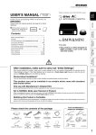
USER’S MANUAL
SECURITY AUTO TIMER
Thank you for purchasing this PIVOT product.
Please read this manual carefully before installation and use.
Please keep this manual for future reference.
T U R B O
● If this produc t is given to
another user, make sure to
include this User’ s Manual.
Product
+
Contents
T I M E R
SECURITY AUTO TIMER
for TURBO and NA
TIME
SECURITY
SET
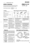
Please check the contents of the package
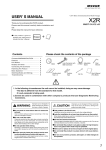
Contents/WARNING/CAUTION ………… 1
Features …………………………………… 2
Part Names ………………………………… 2
Connecting The Wires …………………… 2
Fastening The Product …………………… 3
Settings……………………………………… 3
Explanation Of Function Settings… 3 〜 4
Troubleshooting …………………………… 4
Unit
[86×21×55(D)mm]
Cut Connectors
Large ×3
Small ×1
Zip Ties
×2
Double-sided
Tape
User’s Manual
(This Book)
●Please be sure to check that this product operates properly before fastening it in the car or drilling
holes for installation.
●This product can not be installed in car models which come with a maker-installed push start
system.
●This product is designed solely for 12V models and cannot be installed in 24V models.
●The following devices may not work properly while the Turbo Timer is in operation. If this occurs
please use the devices after the Turbo Timer has completed operation.
・Keyless Entry System or Wireless Door Lock System
・Models equipped with a Security System (Security Alarm System)
WARNING
Improper use or disregard of these warnings
may result in the injury or death of people.
●Do not use the Turbo Timer in the following places or under the
following conditions.
・In places with poor ventilation ・Near flammable items
・When people or animals are in the car
・When the parking brake is not fully engaged
・When an AT model car is a gear other than P (Parking) or an MT model is in
other than N (Neutral)
●Do not wire the cables in places susceptible to shorts, such as
below.
・Near moving parts of the brake or steering wheel
・Near sharp metal parts that may sever the cable
●Please be sure to remove the minus (-) battery cable terminal
from the battery before wiring.
●Do not run the car while the Turbo Timer is in operation.
●Do not use if small children may be lef t alone in car while
parked.
CAUTION
Improper use or disregard of
these warnings may cause
injury to persons, damage the
product and/or other things.
●When installing this product, we recommend that if technical
knowledge becomes necessary please consult your dealer.
● T h i s p r o d u c t i s n o t wate r p r o o f; d o n o t i n s t a l l t o p l a c e s
susceptible to splashing water.
● Make sure to securely insulate all direct connection with
tape or other means.
●In models equipped with an Auto-Light system, make sure to
use only after turning Auto-Light to OFF.
If the setting is at AUTO, the lights will remain ON even after
the engine has been turned off. This may cause the battery
to go dead.
● D o n o t , i n a n y m a n n e r, p r o c e s s , t a k e a p a r t , o r m a k e
changes to this product.
●Do not use electrotap.
1
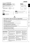
Features
Part Names
●Fully automatic turbo timer with built-in security system.
●Auto setting of idling time in accordance to running time.
●Af ter sto p p in g t h e e n g in e, a fl a s hin g b lu e L E D h e l p s g u ar d
y o u r c a r. B u t u p o n a n y s h o c k o r i m p a c t t o t h e b o d y t h i s
switches to an intimidating high-power high-speed light for a
determined amount of time.
●Countdown to operation and alarm notification.
●Possible to make desired idling time settings.
●T i m e r a l l o w s u p t o 15 - m i n u t e w a r m - u p r u n n i n g f o r a i r
conditioner etc…
●Two 360W high capacity relays guarantee stable operation.
●The 21mm-thin compact body.
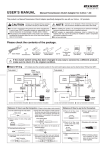
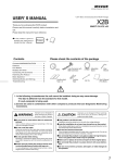
Select one of the following two wiring methods.
Specialized Harness
(sold separately)
Key Cylinder
Orange
(Extra wire)
※not used under
normal conditions.
Brown
3-pin
Connector
Parking Brake Switch
Black
Parking Brake
Lever
Earth
: Use Cut Connector (Small)
Wiring Method
B
Key
Cylinder
Red
Orange
(Extra wire)
※not used under
normal conditions.
Yellow
Blue
Unit
Brown
Parking Brake Switch
Black
Earth
: Use Cut Connector (Large)
3-pin connector wiring
Parking Brake
Lever
: Use Cut Connector (Small)
Red Normal 12V
Security LED
Switch
SPECS
●For DC12V vehicles
●Average Power Consumption in
Standby
Security Mode=8mA
Power Saving Security Mode=3mA
※1 T h e M o d e l S p e c i f i c Tu r b o T i m e r H a r n e s s (s o l d
separately) makes installation a snap.
① Remove the connector connected to the Key Cylinder and
in the middle connect the Specialized Harness (sold
separately).
② Connect the 3-pin connector from the Unit to the 3-pin
connector on the specialized harness.
③ Fasten down the Black wire using a screw on the car
body that carries earth.
④ Using one of the supplied connectors (or by soldering)
securely connect the Brown wire to the wiring of the
parking brake switch.
(Refer to【Reference 1】How to use the Cut Connectors
and【Reference 2】Checking the Parking Brake
Connection Spot at the bottom of page)
10 mm
Peel off of the vinyl
cover at connection.
4
C l o s e t i g ht l y w i t h
cut connector.
2
10 mm
Peel off of the vinyl
cover at the end of
the product’ s wire.
5
Insulate with vinyl
tape.
① Cut off the 3-pin connector from the Unit.
② While referring to the diagram to the left, connect the Red ,
Yellow and Blue wires to the specified places.
③ Fasten down the Black wire using a screw on the car
body that carries earth.
④ Using one of the supplied connectors (or by soldering)
securely connect the Brown wire to the wiring of the
parking brake switch.
(Refer to【Reference 1】How to use the Cut Connectors
and【Reference 2】Checking the Parking Brake
Connection Spot at the bottom of page.)
※2 If there are two 12V wires, connect to the thicker of
the two.
Yellow IG1 (Key ON) 12V
【Reference 1】How to use the Cut Connectors
2
Display
SET
Direct Wiring Method (Without Specialized Harness)
Normal 12V※2
IG1 (Key ON) 12V
IG2 (Key ON) 12V or ACC
1
TIME
SECURITY
for TURBO and NA
Wiring Method Used With Specialized Harness ※1
A
Unit
T I M E R
SECURITY AUTO TIMER
For safety purposes remove the battery cables from the minus
terminals before carrying out the wiring.
Connecting The Wires
Wiring Method
T U R B O
3
Wrap around both
wire coils.
Blue IG2 (Key ON) 12V
If there is no IG2, use ACC
【Reference 2】
Checking the Parking Brake Connection Spot
With the key switch ON (but not the engine)
pull up to cut voltage and push down to
engage 12V power.
●With brake
pulled up: 0V
●With brake
down: 12V
※In AT models, instead
of connecting to the
parking brake, a connection can be made
to the foot brake.
●With foot off the
brake: 0V
※When crimping,
please use crimpers or use pliers to
bend and then
solder together.
●With brake pressed
down: 12V
※Same for the parking brake pedal.
Fastening The Product
Installing The Unit
As shown in the diagram below, use the double-sided tape to fasten
the unit into positions not usually affected by water.
Please be sure to bundle away
all wires with tape, etc…
(How to Install)
(Example of Installation)
While in use if wires become free they may interfere with
driving and cause accidents.
Also, pulling on wires may cause them to short and is
extremely dangerous.
Affix with double-sided tape
to a position which is easy to
see and which allows for
easy operation.
Unit
On the steering
column cover
Double-sided
tape (Included)
Under cover
Clean to remove
oil and dust.
Settings
Time Settings
Switching The Security Mode
Display changes in this order
Press
Switch
Press
Switch
Key Switch Off
Key Switch On
=15 minutes(For Warm-up)
=5 minutes
=1 minutes
=OFF
=9 minutes
=3 minutes
=30 seconds
=Auto
=Security Mode
(Cautionary blinking+Intimidating blinking)
=Power Saving Security Mode
(Cautionary blinking only)
Stopping The Security Mode
Press
Switch
=Security Mode OFF
(All blinking OFF)
Engine Stop
Timer is in Operation
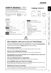
Explanation Of Function Settings
Auto Mode
Auto Time
Auto setting of idling time in accordance to running time from key
switch ON.
Longest Time
Setting
3 min
2 min
1 min
L(30S)
The dot blinks during auto mode.
5 min 15 min 30 min 45 min Running
Time
Manual Mode
Possible to make desired idling time settings.
Security Mode
When key switch is OFF, the LED helps guard your car. But upon any shock or impact to the body this
switches to an intimidating high-power and high-speed light for a determined amount of time (about 5
seconds).
Cautionary Blinking
The LED will continually blink 3 times at regular intervals.
Intimidating Blinking
Upon any shock or impact to the body the LED blinks
highly-power and highly-speed light for a determined
amount of time.
NOTE 1. The intimidating blink will not be activated for 30
seconds after the key is switched OFF to allow
you to get out of the car.
2. If the vibration of getting into to the car causes
the intimidating blink to be activated, turn the key
to ON to stop the blinking.
Cancel Blinking
If there is a reoccurring impact such as heavy rain, the intimidating blink
will be automatically shut off for a period of time to save battery power.
NOTE; If during cancelled status, a strong impact occurs, the cancelled
status will be continued from 30 seconds after the impact.
5
5 more
seconds seconds
Impact
Impact Impact
5
5
5
30 seconds
seconds seconds seconds (Cancelled Status)
Cancel Blinking
1 time in
3 seconds
Warning
Status
Impact Impact
Impact
Return to
Cautionary
Blinking
Impact during this period
will result in canceling.
3
Opening Display
Warning about Mistaken Take Off
1. If emergency brake is released when timer is in
o p e r a t i o n t h e s a fe t y m e c h a n i s m w i l l b e
activated stopping the engine and "P" will be
shown in the display.
When the key is turned ON, the display will show the number of intimidating
blinking cycles from the time the key was turned OFF until switched ON.
(Example)
=
32 times
2. If the Turbo Timer does not work, when the key
is turned OFF and "P" is shown in the display,
the emergency brake has not been pulled up
far enough. Make sure to activate the
emergency brake.
NOTE 1. The number of cycles is not the number of blinks, but 1 cycle
represents the number of times the blinking continued for 5 seconds
due to impact or shock.
2. The cycle number will depend on the area where your car is parked,
with the number becoming larger in places where there is heavy
traffic or heavy rain. If there is no need for the intimidating blink,
please change the setting to a different mode.
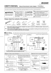
Troubleshooting
(Troubleshooting for some special car models)
The following devices may not work properly while the Turbo Timer is in operation.
If this occurs please use the devices after the Turbo Timer has completed operation.
1. Keyless Entry System or Wireless Door Lock System
2. Models equipped with a Security System (Security Alarm System)
Cars with Automatic
Light Controller
When using the Timer in a car equipped operating with an auto light control system, the lights may not turn off
when using the Timer with auto light turned on even after the engine has stopped. If this is the case, when
using the Timer make sure to not use Auto Mode for the light control system.
Trouble
Possible Causes
Possible Solutions
The key switch is set
to ON but the display
will not light up.
An improper harness for your car model has been used.
Please reconfirm whether wiring and connections are
correct or not.
T h e Tu r b o T i m e r
does not work.
An improper harness for your car model has been used.
The Red , Yellow , Blue or Black wires may have
been improperly wired or there is a poor connection.
Please reconfirm whether wiring and connections are
correct or not.
The Red , Yellow , Blue or Brown wires may have
been improperly wired or there is a poor connection.
The Turbo Timer setting is set to OFF.
The display lights up,
but the engine stops.
(If the Turbo Timer is set to [AUTO].)
Engine operation time is short.
Turn the key switch to OFF after running the engine at
least 5 minutes.
An improper harness for your car model has been used.
Please reconfirm whether wiring and connections are
correct or not.
The Red , Yellow or Blue wires may have been
improperly wired or there is a poor connection.
The polarity of the special harness is incorrect.
●In some special harnesses the IG1 ( Yellow ) and
IG2 ( Blue ) positions are reversed. If this is the case,
try switching the Yellow and Blue wires of the 3-pin
connector coming out from the unit.
S w i t c h t h e Ye l l o w
and Blue wires on the
3-pin connector coming
out from the unit.
How to Re-connect
Pull out the wire while
pressing in
(Present Condition)
(After Fixing)
Note, that doing this in other car models will render the
Timer inoperative, so please return the wires to their
original connection positions.
(Figure as seen from the
terminal side)
Red
Blue
The engine stops if the during idling torque is too weak.
Red
Blue
Yellow
Yellow
In order to increase the torque, increase the engine
rotation to 1200-1500 rpm and turn off the key switch to
start the Turbo Timer operation.
"P" is shown in the display and the Turbo Timer does not work.
The emergency brake has not been pulled up far enough. Make sure to activate the emergency brake.
※Our products have already been recognized as our Industrial Property or are in the process of receiving Industrial Property status.
※We plan in the near future to take all possible legal measures to protect against unfair competition from look-alike products using similar
designs, regulating characteristics, circuitry and circuitry layout.
※We strictly prohibit the unlicensed use of the PIVOT trademark and the unauthorized use of PIVOT User’ s Manual.
4
PIVOT CORPORATION
87-3, Shimookada Okada, Matsumoto-shi, Nagano, 390-0313 Japan TEL0263-46-5901
http://pi votj p.c om /