1
(THA-MA1/MA2 As of March, 2015 No.5)
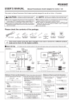
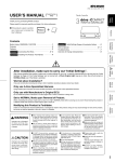
USER’S MANUAL
Manual Transmission Clutch Adaptor
Product Number :
(THA-MA1/MA2 )
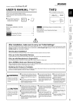
This product is a Manual Transmission Clutch Adaptor specifically designed for use with our 3-drive Series(Cruthro).
●Do not use in conjunction
with products from other
manufacturers. In such a
case, PIVOT Corporation
accepts no responsibility, in
any manner whatsoever,
for any damage or trouble,
direct or indirect.
WARNING
Improper use or disregard of
these warnings may result in
the injury or death of people.
●When installing this product, we recommend
that if technical knowledge becomes necessary
please consult a qualified mechanic.
●PIVOT accepts no responsibility whatsoever,
direct or indirect for any troubles that may
occur if this product is modified or used in
conjunction with another company’ s product.
●Do not use electrotap.
CAUTION
Improper use or disregard of
these warnings may cause
injury to persons, damage
the product and/or other
things.
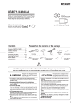
Please check the contents of the package.
Cut
Connectors× 3
Clutch Adapter
Male Connector
Male Sleeve
Female Connector
Female Sleeve
Double-sided
Tape
[25×35 mm]
Zip Tie
USER’ S
MANUAL
Wiring
Chart
(MT)
User’s Manual
(This Book)
Wiring Chart (MT)
(in Japanese)
If the clutch switch wiring has been changed in any way to connect to a different product, make sure to
return it to its original condition.
If the product is not installed properly it may result in poor operation including that the product does not
work or the AUTO CRUISE function does not run properly.
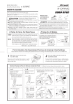
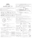
■Basic Wiring
※For details about the connection position for the clutch switch signal, please see the attached sheet “Wiring Chart (MT)”.
THA-MA1
: Use Connector
: Use Cut Connector
THA-MA2
: Use Connector
: Use Cut Connector
(Clutch Switch Signal)
Brown
or
Green
※1
Yellow
Clutch
Adapter
Brown
Clutch
Adapter
(Clutch
Switch Signal)
Red Gray Purple
Gray Purple
Black
Black
Earth
Clutch
Pedal
Red
※1
Earth
Gray (to Brake
3-drive
(IGN)
Switch)
Clutch
Pedal
Gray
3-drive
Red
(to Brake
Switch)
Cut off the insulation of the tip of the codes, Brown and Green
code which you need to connect, then bundle the extra code.
【Reference 1】How to use the Connectors (Figure is shown using a male connector)
① Pull the cable through the male sleeve.
Male sleeve
Wire
② Remove about 10 mm of the cable
casing.
⑤ Crimp down with crimpers to make sure that
the inner wires are firmly connected to the
inner par t of the connector and that the
cable section is connected to the outer part
of the connector.
④ Connect the male connector to the end
of the cable.
Male Connector
① Pe e l o f f o f t h e v i ny l
cover at connection.
④Close tightly with cut
connector.
10 mm
Crimp these places
10 mm
③ Turn back the tip of the wires.
【Reference 2】How to use the Cut Connectors
⑥Affix the male sleeve to the places as
mentioned above.
※After connecting the male and female
connectors, make sure to firmly twist the
male sleeve inside the female sleeve.
② Pe e l o f f o f t h e v i n y l
cover at the end of the
product’ s wire.
⑤Insulate with vinyl tape.
10 mm
③Wrap around both wire
coils.
※When crimping, please
use crimpers or use
pliers to bend and then
solder together.
Connecting The Wires
1
Wiring
Chart
(MT)
Connect to the Clutch Switch Signal
(Common for both THA-MA1 and THA-MA2)
3
Connect to the Brake Switch Signal
(Common for both THA-MA1 and THA-MA2)
① Cut the Gray wire of the 3-drive at an appropriate place. Using the supplied connectors attach the female connector to the brake switch wire and the male connector to the
3-drive wire.
After confirming the connection position for your model car as
shown on the attached sheet “Wiring Chart (MT)” , connect the
Brown or Green wire using one of the supplied cut connectors.
※Some models may have two clutch switches, please connect
to the same connector as listed under “Connector Design” in
the “Wiring Chart (MT)” .
( ⇒ Refer to 【Reference
“
1】How to use the Connectors” .)
(⇒ Refer to 【Reference
“
2】How to use the Cut Connectors”.)
For customers using THA-MA1, make sure to insulate the wire ( Brown
or Green ) left unconnected.
Male
Connector
e.g.) HONDA CIVIC
メーカー
車名
アダプター
品番
HONDA
シビック
THA-MA1
Brown
コネクター 接続コード色
形状
ア
イ
MTC-2
茶
2
Female
Connector
(to Brake
Switch)
② Connect the Gray wire and the Purple wire from the
adaptor to the just attached connectors.
Wire Color
for
Connection
Clutch
Adapter
Clutch
Switch
Connector
ア
イ
ア イ
Gray
3-drive
Gray Purple
Brown
(MTC-2) (Wire leading from product)
Gray
3-drive
Connect for Adaptor Power
●For THA-MA1
(to Brake
Switch)
Using one of the supplied cut connectors, connect the Red
wire of the Adaptor to the Red wire of the 3-drive.
4
●For THA-MA2
Using one of the supplied cut connectors, connect the
Yellow wire of the Adaptor to the clutch switch IGN wire
(12V with key ON).
Connect for Earth
(Common for both THA-MA1 and THA-MA2)
Using one of the supplied cut connectors, connect the Black
wire of the Adaptor to the Black wire of the 3-drive.
( ⇒ Refer to “【Reference 2】How to use the Cut Connectors”.)
Confirm the Connection
Connecting the tip of the Voltage Detector to Gray wire of Clutch Adaptor
and if it’s 12V(LED Lamp ON) when pressing the brake pedal or the clutch
pedal, connection is correct. It’s 0V(LED Lamp OFF) when releasing the
pedal. (⇒Refer to User’s Manual of 3-drive series.)
3-drive
Gray
Gray
Clutch
Adapter
Voltage Detector
LED
Earth
Installing The Product
Test Drive
Use the double-sided tape
(included) to fasten the
units into positions not
usually affected by water.
After having fully read sections “Basic Operation”
and “How to Operate” of the “3-drive User’ s
Manual” take a test drive.
(How to Install)
Double-sided
tape
(Included)
Clean to
remove
oil and dust.
Please be sure
to bundle away all wires with tape, etc…
While in use if wires become free they may interfere
with driving and cause accidents. Also, wires which
are smashed or crushed may result in a short and
can be extremely dangerous.
After installation, make sure to carry out
“INITIAL SETTINGS” and “Speed Pulse Settings”
Make sure to carr y out all “Initial Set tings” and
“ Speed Pulse Set tings” of the “ 3 - drive User ’ s
Manual”. If these settings are not carried out the
product will not run properly.
If while in AUTO CRUISE, pressing down on the
clutch pedal deactivates the AUTO CRUISE function
the adaptor is working properly.
Usage Note
In some car models it is necessary to fully press
down on the clutch to activate the clutch switch
signal. When deactivating AUTO CRUISE make
sure to fully depress the clutch. Pushing down only
half way will cause the engine rotation to increase.
Troubleshooting
Trouble
Possible Causes
Possible Solutions
AUTO CRUISE does not Operate.
Each wire may have been improperly wired or there
is a poor connection.
Please reconfirm whether wiring and connections are
correct or not.
AUTO CRUISE is automatically
d e a c t i va t e d a n d t h e d i s p l ay
switches to throttle controller.
Each wire may have been improperly wired or there
is a poor connection.
Please reconfirm whether wiring and connections are
correct or not.
The clutch pedal is not fully pressed down all the way.
Make sure to press down fully on the clutch pedal.
The Brown or Green wires may have been improperly
wired or there is a poor connection.
Please reconfirm whether wiring and connections are
correct or not.
The clutch pedal is pressed down
bu t AU TO C RU I S E d o e s n o t
deactivate.
PIVOT CORPORATION
87-3, Shimookada Okada, Matsumoto-shi, Nagano, 390-0313 Japan TEL0263-46-5901