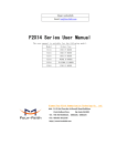
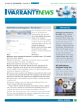
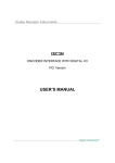
1
F8X14 Series
User Manual
Documentation No.
Product
Version
Product Name:
Page
Total:
F8X14 Series User Manual
The user manual is suitable for the following model:
Model
Product Type
F8114
ZigBee + GPRS IP MODEM
F8214
ZigBee + CDMA IP MODEM
F8314
ZigBee + EDGE IP MODEM
F8414
ZigBee + WCDMA IP MOEM
F8514
ZigBee + TD-SCDMA IP MOEM
F8614
ZigBee + EVDO IP MOEM
Xiamen FourFour-Faith Communication Technology Co., Ltd.
:
Add J1-J3,3rd Floor,No.44,GuanRi Road,SoftWare
:
Park,XiaMen,China
Tel +86 592-6300326
Zip Code:361008
,6300325,6300324
Fax:+86 592-5912735
http://www.fourfaith.com
User Manual
Files Revised Record
Date
Version
Remark
Author
2011.04.19
V0.5
Draft
Tracy.zheng
2011.06.28
V0.6
Modification
Tracy.zheng
2011.07.14
V0.7
Modification
Tracy.zheng
Xiamen Four-Faith Communication Technology Co.,Ltd.
Page 2 of 48
rd
Add: J1-J3,3 Floor,No.44,GuanRiRoad,SoftWare Park,XiaMen .361008.China
http://www.fourfaith.com
Tel: +86 592-6300326 6300325 6300324
Fax:+86 592-5912735
User Manual
Copyright Notice
All contents in the files are protected by copyright law, and all copyrights are reserved by Xiamen
Four-Faith Communication Technology Co., Ltd. Without written permission, all commercial
use of the files from Four-Faith are forbidden, such as copy, distribute, reproduce the files, etc.,
but non-commercial purpose, downloaded or printed by individual (all files shall be not revised,
and the copyright and other proprietorship notice shall be reserved) are welcome.
Trademark Notice
Four-Faith 、四信、
、
、
are all registered trademarks of Xiamen
Four-Faith Communication Technology Co., Ltd., illegal use of the name of Four-Faith,
trademarks and other marks of Four-Faith is forbidden, unless written permission is authorized in
advance.
Xiamen Four-Faith Communication Technology Co.,Ltd.
Page 3 of 48
rd
Add: J1-J3,3 Floor,No.44,GuanRiRoad,SoftWare Park,XiaMen .361008.China
http://www.fourfaith.com
Tel: +86 592-6300326 6300325 6300324
Fax:+86 592-5912735
User Manual
Xiamen Four-Faith Communication Technology Co.,Ltd.
Page 4 of 48
rd
Add: J1-J3,3 Floor,No.44,GuanRiRoad,SoftWare Park,XiaMen .361008.China
http://www.fourfaith.com
Tel: +86 592-6300326 6300325 6300324
Fax:+86 592-5912735
User Manual
Contents
Chapter 1 Brief Introduction of Product ........................................................................................... 6
1.1 General ................................................................................................................................ 6
1.2 Features and Benefits .......................................................................................................... 6
1.3 Working Principle ............................................................................................................... 7
1.4 Specifications ...................................................................................................................... 8
Chapter 2 Installation Introduction ................................................................................................. 12
2.1 General .............................................................................................................................. 12
2.2 Encasement List ................................................................................................................ 12
2.3 Installation and Cable Connection .................................................................................... 12
2.4 Power ................................................................................................................................ 15
2.5 Indicator Lights Introduction ............................................................................................ 15
Chapter 3 Configuration.................................................................................................................. 16
3.1 Configuration Connection ................................................................................................. 16
3.2 Configuration Introduction................................................................................................ 16
3.3 Run the configure Tool: IP Modem Configure.exe ........................................................... 17
3.4 Re-power IP MODEM ...................................................................................................... 18
3.5 Configuration .................................................................................................................... 18
3.5.1 Data Service Center Settings .................................................................................. 18
3.5.2 IP MODEM Settings .............................................................................................. 21
3.5.3 Other Settings ......................................................................................................... 26
3.5.4 Scheduled Power ON/OFF Setting ........................................................................ 29
3.5.5 ZigBee Setting..................................................................................................... 38
3.6 Functions ........................................................................................................................... 41
3.7 Work State Switch ............................................................................................................. 43
Appendix ......................................................................................................................................... 45
Xiamen Four-Faith Communication Technology Co.,Ltd.
Page 5 of 48
rd
Add: J1-J3,3 Floor,No.44,GuanRiRoad,SoftWare Park,XiaMen .361008.China
http://www.fourfaith.com
Tel: +86 592-6300326 6300325 6300324
Fax:+86 592-5912735
User Manual
Chapter 1 Brief Introduction of Product
1.1 General
F8X14 IP MODEM is a kind of data terminal device that provides data transfer function by
public cellular network and ZigBee network.
It adopts high-powered industrial 32 bits CPU and embedded real time operating system. It
supports RS232, RS485 (or RS422) and ZigBee port that can conveniently and transparently
connect one device to a cellular network, allowing you to connect to your existing serial and
ZigBee devices with only basic configuration. It has low power consumption states in which the
power consumption could be 1ower than 1mA@12VDC. It has compatible digital I/O channel,
ADC, input pulse counter and pulse wave output function.
It has been widely used on M2M fields, such as intelligent transportation, smart grid,
industrial automation, telemetry, finance, POS, water supply, environment protection, post,
weather, and so on.
1.2 Features and Benefits
Design for Industrial Application
High-powered industrial cellular module
High-powered industrial ZigBee module
High-powered industrial 32 bits CPU
Support low power consumption mode, including multi-sleep and trigger modes to reduce the
power dissipation farthest
Embedded Real Time Clock(RTC) circuit which can realize timing online/offline function
Housing: iron, providing IP30 protection
Power range: DC 5~35V
Stability and Reliability
Xiamen Four-Faith Communication Technology Co.,Ltd.
Page 6 of 48
rd
Add: J1-J3,3 Floor,No.44,GuanRiRoad,SoftWare Park,XiaMen .361008.China
http://www.fourfaith.com
Tel: +86 592-6300326 6300325 6300324
Fax:+86 592-5912735
User Manual
Support hardware and software WDT
Support auto recovery mechanism, including online detect, auto redial when offline to make
it always online
RS232/RS485/RS422 port: 15KV ESD protection
SIM/UIM port: 15KV ESD protection
Power port: reverse-voltage and overvoltage protection
Antenna port: lightning protection(optional)
Standard and Convenience
Adopt terminal block interface, convenient for industrial application
Support standard RS232 and RS485(or RS422) port that can connect to serial devices directly
TTL logic level RS232 interface can be customized
Support intellectual mode, enter into communication state automatically when powered
Provide management software for remote management
Support several work modes
Convenient configuration and maintenance interface
High-performance
Support data transfer by cellular and ZigBee network
Support TCP server and support multi TCP client connection(optional)
Support double data centers, one main and another backup
Supply 5 I/O channels, compatible 2 pulse wave output channels, 2 analog inputs and one
pulse input counters.
Support multi data centers and it can support 5 data centers at the same time
Support multi online trigger ways, including SMS, ring and data. Support link disconnection
when timeout
Support dynamic domain name(DDNS) and IP access to data center
Design with standard TCP/IP protocol stack
Support APN/VPDN
1.3 Working Principle
The principle chart of the IP MODEM is as following:
Xiamen Four-Faith Communication Technology Co.,Ltd.
Page 7 of 48
rd
Add: J1-J3,3 Floor,No.44,GuanRiRoad,SoftWare Park,XiaMen .361008.China
http://www.fourfaith.com
Tel: +86 592-6300326 6300325 6300324
Fax:+86 592-5912735
User Manual
SRAM&
FLASH
RTC Module
MCU
WDT Module
Indicator
Lights
RS232/RS485/RS422
Cellular
Module
Module
Antenna
SIM/UIM
Interface
Power Module
User Interface
1.4 Specifications
Cellular Specification
F8114 Specification
Item
Cellular Module
Standard and Band
Content
Industrial cellular module
EGSM900/GSM1800MHz,
GSM850/900/1800/1900MHz(optional)
Compliant to GSM phase 2/2+
GPRS class 10, class 12(optional)
Bandwidth
85.6Kbps
TX power
GSM850/900: <33dBm
GSM1800/1900: <30dBm
RX sensitivity
<-107dBm
F8214 Specification
Item
Cellular Module
Standard and Band
Content
Industrial cellular module
CDMA2000 1xRTT 800MHz
CDMA800/1900MHz(optional)
CDMA450MHz(optional)
Bandwidth
153.6Kbps
TX power
<30dBm
RX sensitivity
<-104dBm
F8314 Specification
Item
Cellular Module
Standard and Band
Content
Industrial cellular module
GSM850/900/1800/1900MHz
GPRS/EDGE Class 12
Xiamen Four-Faith Communication Technology Co.,Ltd.
Page 8 of 48
rd
Add: J1-J3,3 Floor,No.44,GuanRiRoad,SoftWare Park,XiaMen .361008.China
http://www.fourfaith.com
Tel: +86 592-6300326 6300325 6300324
Fax:+86 592-5912735
User Manual
Bandwidth
236.8Kbps
TX power
GSM850/900:<33dBm
GSM1800/1900:<30dBm
RX sensitivity
<-106dBm
F8414 Specification
Item
Cellular Module
Standard and Band
Content
Industrial cellular module
UMTS/WCDMA/HSDPA/HSUPA 850/1900/2100MHz
UMTS/WCDMA/HSDPA/HSUPA 850/900/1900/2100MHz(optional)
GSM850/900/1800/1900MHz
GPRS/EDGE CLASS 12
Bandwidth
HSUPA: 5.76Mbps(上行) / HSDPA: 7.2Mbps(下行)/UMTS: 384Kbps (DL/UL)
TX power
<24dBm
RX sensitivity
<-109dBm
F8514 Specification
Item
Cellular Module
Standard and Band
Content
Industrial cellular module
TD-SCDMA/HSDPA/HSUPA 1880-1920/2010-2025MHz
GSM850/900/1800/1900MHz 四频
GPRS/EDGE CLASS 12
Bandwidth
2.8Mbps(down), 2.2Mbps(up)
TX power
<24dBm
RX sensitivity
<-108dBm
F8614 Specification
Item
Cellular Module
Standard and Band
Content
Industrial cellular module
CDMA2000 1X EVDO Rev A 800MHz
CDMA2000 1X EVDO Rev A 800/1900MHz (optional)
CDMA2000 1X EVDO Rev A 450MHz (optional)
IS-95 A/B 、CDMA2000 1xRTT
Bandwidth
3.1Mbps(down), 1.8Mbps(up)
TX power
<23dBm
RX sensitivity
<-104dBm
ZigBee Specification
Item
ZigBee Module
Standard and Band
Content
Industrial ZigBee module
IEEE 802.15.4
ISM 2.4 GHz
Indoor/Urban Range
60m
90m(for enhanced version)
Outdoor/RF Line-of-Sight
100m
Xiamen Four-Faith Communication Technology Co.,Ltd.
Page 9 of 48
rd
Add: J1-J3,3 Floor,No.44,GuanRiRoad,SoftWare Park,XiaMen .361008.China
http://www.fourfaith.com
Tel: +86 592-6300326 6300325 6300324
Fax:+86 592-5912735
User Manual
Range
800m(for enhanced version)
0dBm
Transmit Power
22dBm (for enhanced version)
Bandwidth
250Kbps
Receiver Sensitivity
Network Topologies
Number of channels
Channels
Max packge size
-95dBm
-104dBm(for enhanced version)
Point-to-Point, Point-to-Multipoint, Peer-to-Peer and Mesh
16 Direct Sequence Channels
15 Direct Sequence Channels (for enhanced version)
11 to 26
11 to 25 (for enhanced version)
100Bytes (on Broadcast workmode)
1024 Bytes (on Master-Client and Accord workmode)
Hardware System
Item
CPU
Content
Industrial 32 bits CPU
FLASH
512KB(Extendable)
SRAM
256KB(Extendable)
Interface Type
Item
Serial
Content
1 RS232 port and 1 RS485(orRS422) port, 15KV ESD protection
Data bits: 5, 6 ,7, 8
Stop bits: 1, 1.5, 2
Parity: none, even, odd, space, mark
Baud rate: 110~230400 bps
Indicator
“ZigBee”
"Power", "ACT", "Online",
Antenna
Cellular: Standard SMA female interface, 50 ohm
GPS: Standard SMA female interface, 50 ohm
lighting protection(optional)
SIM/UIM
Power
Standard 3V/1.8V user card interface, 15KV ESD protection
Terminal block interface, reverse-voltage and overvoltage protection
Xiamen Four-Faith Communication Technology Co.,Ltd.
Page 10 of 48
rd
Add: J1-J3,3 Floor,No.44,GuanRiRoad,SoftWare Park,XiaMen .361008.China
http://www.fourfaith.com
Tel: +86 592-6300326 6300325 6300324
Fax:+86 592-5912735
User Manual
Power Input
Item
Standard Power
Power Range
Content
DC 12V/0.5A
DC 5~35V
Power Consumption
Working States
Power Consumption
Communication
50-90mA@12VDC;115-165mA@5VDC
Standby
25mA@12VDC;45mA@5VDC
Sleep
8mA@12VDC;18mA@5VDC
Timing Power
Off
0.6mA@12VDC;1mA@5VDC
Physical Characteristics
Item
Housing
Dimensions
Weight
Content
Iron, providing IP30 protection
91x58.5x22 mm
210g
Environmental Limits
Item
Content
Operating
Temperature
-25~+65ºC(-13~+149℉)
Extended
Operating
Temperature
-30~+75ºC(-22~+167℉)
Storage
Temperature
-40~+85ºC(-40~+185℉)
Operating
Humidity
95% ( Non-condensing)
Xiamen Four-Faith Communication Technology Co.,Ltd.
Page 11 of 48
rd
Add: J1-J3,3 Floor,No.44,GuanRiRoad,SoftWare Park,XiaMen .361008.China
http://www.fourfaith.com
Tel: +86 592-6300326 6300325 6300324
Fax:+86 592-5912735
User Manual
Chapter 2 Installation Introduction
2.1 General
The IP MODEM must be installed correctly to make it work properly.
Warning: Forbid to install the IP MODEM when powered!
2.2 Encasement List
Name
Quantity
Remark
IP MODEM host
1
2.4G ZigBee Antenna
1
Cellular Antenna
1
Power adapter
1
RS232 data cable
1
optional
RS485 data cable
1
optional
Manual CD
1
Certification card
1
Maintenance card
1
Table 2-1 Encasement List
2.3 Installation and Cable Connection
Dimension: (unit: mm)
Xiamen Four-Faith Communication Technology Co.,Ltd.
Page 12 of 48
rd
Add: J1-J3,3 Floor,No.44,GuanRiRoad,SoftWare Park,XiaMen .361008.China
http://www.fourfaith.com
Tel: +86 592-6300326 6300325 6300324
Fax:+86 592-5912735
User Manual
8
22
28
4
Ф3
Ф5
35
25
28
58.5
Figure 2-1 Installation Chart
Installation of SIM/UIM card:
Firstly power off the IP MODEM, and press the out button of the SIM/UIM card outlet with a
needle object. Then the SIM/UIM card sheath will flick out at once. Put SIM/UIM card into the
card sheath (Pay attention to put the side which has metal point outside), and insert card sheath
back to the SIM/UIM card outlet.
Warning: Forbid to install SIM/UIM card when powered!
Installation of antenna:
Screw the SMA male pin of the antenna to the female SMA outlet of the IP MODEM tightly.
Warning: The antenna must be screwed tightly, or the signal quality of antenna will be influenced!
User Interface Signal Definition
Pin Number
Signal Name
Default Function
Extensible Function
1
PWR
Power input anode
N/A
2
GND
Power Ground
N/A
3
GND
Power Ground
N/A
4
RX
RS232 RX
N/A
5
TX
RS232 TX
N/A
6
A
RS485 anode
Reserved compatible DTR
7
B
RS485 cathode
Reserved compatible DSR
8
IO1
GPIO
Reserved compatible RTS and
RS232 RX (TTL logic level)
9
IO2
GPIO
Reserved compatible CTS and
RS232 TX (TTL logic level)
10
IO3
GPIO
Reserved compatible DCD
Xiamen Four-Faith Communication Technology Co.,Ltd.
Page 13 of 48
rd
Add: J1-J3,3 Floor,No.44,GuanRiRoad,SoftWare Park,XiaMen .361008.China
http://www.fourfaith.com
Tel: +86 592-6300326 6300325 6300324
Fax:+86 592-5912735
User Manual
11
IO4
GPIO
Reserved compatible RI,ADC,
and pulse output
12
IO5
GPIO
Reserved compatible pulse wave
input counter, ADC, and pulse
output
Installation of cable:
F8X14 adopts industrial terminal block interface. The recommendatory cable is 28-16AWG.
The detail description of standard layout adapter and communication cables as is following:
Adapter(Rating Output 12VDC/0.5A)
:
Cable Color
Power Output Polarity
Black &White Alternate
Anode
Black
Cathode
RS232 Cable:
Cable Color
Corresponding DB9-M Pin Number
Brown
Pin 2
Blue
Pin 3
Black
Pin 5
RS485 Cable:
Cable Color
Signal definition
Red
RS485(A)
Black
RS485(B)
Xiamen Four-Faith Communication Technology Co.,Ltd.
Page 14 of 48
rd
Add: J1-J3,3 Floor,No.44,GuanRiRoad,SoftWare Park,XiaMen .361008.China
http://www.fourfaith.com
Tel: +86 592-6300326 6300325 6300324
Fax:+86 592-5912735
User Manual
Power adapter and communication cable connection chart as following:
F8X14 Terminal
Block Interface
1
2
3
4
5
6
7
8
9
10
11
12
PWR
GND
GND
RX
RX
TX
A
B
IO1
IO2
IO3
IO4
IO5
F8X14 Terminal
Block Interface
User Device
(DB9M)
+ Anode
- Cathode
1
2
3
4
5
6
7
8
9
PWR
GND
RX
TX
GND
RX
TX
A
GND
B
IO1
IO2
IO3
IO4
IO5
Communication Interface: RS232
1
2
3
4
5
6
7
8
9
10
11
12
User Device
+ Anode
- Cathode
A
B
Communication Interface: RS485
2.4 Power
The power range of the IP MODEM is DC 5~35V
Warning: When we use other power, we should make sure that the power can supply power
above 4W.
We recommend user to use the standard DC 12V/0.5A power adaptor.
2.5 Indicator Lights Introduction
The IP MODEM provides three indicator lights: “Power”, “ACT”, “Online”.
Indicator
Light
Power
ACT
Online
ZigBee
State
Introduction
ON
IP MODEM is powered on
OFF
IP MODEM is powered off
BLINK
Data is communicating
OFF
No data
ON
IP MODEM has logged on network
OFF
IP MODEM hasn’t logged on network
ON
ZigBee Transport data
OFF
No data
Xiamen Four-Faith Communication Technology Co.,Ltd.
Page 15 of 48
rd
Add: J1-J3,3 Floor,No.44,GuanRiRoad,SoftWare Park,XiaMen .361008.China
http://www.fourfaith.com
Tel: +86 592-6300326 6300325 6300324
Fax:+86 592-5912735
User Manual
Chapter 3 Configuration
3.1 Configuration Connection
Before configuration, It’s necessary to connect the IP MODEM with the configure PC by the
shipped RS232 or RS232-485 conversion cable as following.
3.2 Configuration Introduction
There are two ways to configure the IP MODEM:
Configuration software tool: All the settings are configured through the shipped software tool.
It’s necessary to have one PC to run this tool.
Extended AT command: All the settings are configured through AT command, so any device
with serial port can configure it. Before configuration with extended AT command, you should
make IP MODEM enter configure state. The steps how to make IP MODEM enter configure
state, please refer to appendix.
The following describes how to configure IP MODEM with the configure software tool. At the
same time, it gives out the corresponding AT command of each configuration item.
Xiamen Four-Faith Communication Technology Co.,Ltd.
Page 16 of 48
rd
Add: J1-J3,3 Floor,No.44,GuanRiRoad,SoftWare Park,XiaMen .361008.China
http://www.fourfaith.com
Tel: +86 592-6300326 6300325 6300324
Fax:+86 592-5912735
User Manual
3.3 Run the configure Tool: IP Modem Configure.exe
The “Serial Parameters” column shows the current serial port settings. To configure IP
MODEM, please choose the correct serial port which connects to IP MODEM, and the baud-rate
is 115200 with no parity, then open the serial port. If the button text is“Close”, it shows the serial
port now has been opened. If the text is “Open”, you should open the port first. When the port
opened, the “Output Info” column will display
“Port(COM1) Has Opened,Please Re-Power the IP MODEM,
Waiting IP MODEM Enter Configure State...”
Xiamen Four-Faith Communication Technology Co.,Ltd.
Page 17 of 48
rd
Add: J1-J3,3 Floor,No.44,GuanRiRoad,SoftWare Park,XiaMen .361008.China
http://www.fourfaith.com
Tel: +86 592-6300326 6300325 6300324
Fax:+86 592-5912735
User Manual
3.4 Re-power IP MODEM
After Re-power IP MODEM, The configure tool will make it enter configure state. At the
same time, the software will load current settings from IP MODEM and displays on the right
configure columns. It’s now ready to configure.
3.5 Configuration(F8114 for example)
3.5.1 Data Service Center Settings
Settings on this page are the parameters related to Data Service Center (DSC).
◆Data Center Number
IP MODEM support two Data Service Center methods to transmit data.
Main and Backup: IP MODEM always tries to connect with the Main DSC. If fails to connect
with Main DSC, it will connect with Backup DSC at once
Note:If no Backup DSC exists, please configure the Backup DSC same as Main DSC.
Xiamen Four-Faith Communication Technology Co.,Ltd.
Page 18 of 48
rd
Add: J1-J3,3 Floor,No.44,GuanRiRoad,SoftWare Park,XiaMen .361008.China
http://www.fourfaith.com
Tel: +86 592-6300326 6300325 6300324
Fax:+86 592-5912735
User Manual
Multi Data Service Center: IP MODEM can connect with at most five DSC at the same time.
All the multi DSC can receive the same application data .
If the Data Center Number is 0,there is no DSC working.
If the Data Center Number is 1, IP MODEM work in Main and Backup DSC method.
When “Data Center Number” is greater than 1, IP MODEM works in Multi Data Service Center
method
GPS data transmission DSC is self-governed. Setting details please reference the section 3.5.5.
AT command:
AT+SVRCNT=x
x: Data Service Center number
Note: every AT command is terminated with a enter character.
◆Main Center Addr+Port:
IP Address and Port of the Main DSC, It’s better to set the port greater than 1024.
AT command of the Main DSC IP address or domain name:
AT+IPAD=xxx
xxx: The IP address or domain name.
AT command of the Main DSC port:
AT+PORT=xxx
xxx: The port value
◆Backup Center Addr+Port:
IP address and port of the Backup DSC
AT command of the Backup DSC IP address or domain
AT+IPSEC=xxx
xxx: The IP address or domain name
AT command of the Backup DSC port
AT+PTSEC=xxx
xxx: The port value
◆Multi DSC Configuration
Xiamen Four-Faith Communication Technology Co.,Ltd.
Page 19 of 48
rd
Add: J1-J3,3 Floor,No.44,GuanRiRoad,SoftWare Park,XiaMen .361008.China
http://www.fourfaith.com
Tel: +86 592-6300326 6300325 6300324
Fax:+86 592-5912735
User Manual
When “Data Center Number” is greater than 1, this setting is valid. For example,setting the
“Data Center Number” as 3, Main Center, 2nd Center, 3rd Center work as these three DSC
AT Command of the 2~5 DSC IP address or domain name
AT+IPADn=xxx
n is 1~4 correspond to center 2~5
xxx: The IP address or domain name
AT Command of the 2~5 DSC port
AT+PORTn=xxx
n is 1~4 correspond to port of center 2~5
xxx: The port value
Example:
Set IP address of center 3 as 166.111.8.238, and port 5001, the AT command is as following:
AT+IPAD2=166.111.8.238
AT+PORT2=5001
◆ Main and Backup Center DNS Server
When the DSC Internet access uses domain name, It’s necessary to set DNS server resolving the
DSC domain name. When the Data Center Number is 1, Main and Backup Center DNS Server is
used to resolve the Main center and Backup center correspondingly.
AT command of Main Center DNS server:
AT+DNSSVR=aaa.bbb.ccc.ddd
aaa.bbb.ccc.ddd: The DNS server IP address(must be IP address).
AT command of Backup Center DNS server:
AT+DNSSV2=aaa.bbb.ccc.ddd
Xiamen Four-Faith Communication Technology Co.,Ltd.
Page 20 of 48
rd
Add: J1-J3,3 Floor,No.44,GuanRiRoad,SoftWare Park,XiaMen .361008.China
http://www.fourfaith.com
Tel: +86 592-6300326 6300325 6300324
Fax:+86 592-5912735
User Manual
aaa.bbb.ccc.ddd: the DNS server IP address
◆ Center 2~5 DNS Server
When the IP MODEM work in Multi Data Service Center method and the centers use domain
name, 2~5 DNS server is used to resolve center 2~5 correspondingly.
AT command of 2~5 DNS Server
AT+DNSSVRn=aaa.bbb.ccc.ddd
n is 1~4 correspond to center 2~5 DNS server.
aaa.bbb.ccc.ddd is the DNS server IP address
3.5.2 IP MODEM Settings
◆ IP MODEM WorkkMode
According to different application requirements, there are several protocol workmode to choose.
PROT:Heartbeat packet with TCP protocol, Data transmission with TCP protocol, heartbeat
packet and application data transmission are in the same TCP connection.
TRNS:IP MODEM work as a common GPRS MODEM, It can be used in SMS, CSD, Dial-up
applications.
TTRN:Heartbeat packet with UDP protocol, Data transmission with TCP protocol
TLNT:IP MODEM work as a telnet client
LONG:Heartbeat packet with UDP protocol, Data transmission with TCP protocol, It can transmit
at most 8192 bytes data one time through extra application protocol.
LNGT:Heartbeat with UDP protocol, Data transmission with TCP protocol, It can transmit at
most 8192 bytes data one time through extra application protocol.
TUDP:Heartbeat with UDP protocol, Data transmission with UDP protocol, Heartbeat packet and
application data are in the same UDP connection.
SUDP:User can set custom register and heartbeat string, Data transmission with UDP protocol,
Xiamen Four-Faith Communication Technology Co.,Ltd.
Page 21 of 48
rd
Add: J1-J3,3 Floor,No.44,GuanRiRoad,SoftWare Park,XiaMen .361008.China
http://www.fourfaith.com
Tel: +86 592-6300326 6300325 6300324
Fax:+86 592-5912735
User Manual
Heartbeat packet and application data are in the same UDP connection.
TCST:User can set custom register and heartbeat string, Data transmission with TCP protocol.
AT command:
AT+MODE=xxxx
xxxx: one of the above workmode
◆ Trigger Type
Normally, IP MODEM always keeps online and always be ready for data transmission. But in
some circumstances, it’s important to reduce wireless data flow. To realize this function, the
software can makes IP MODEM into sleep state in idle time. When there is application data to
transmit, IP MODEM can be triggered online ready for data transmission. There are total five
methods to make IP MODEM online:
AUTO: IP MODEM always keeps online
SMSD: send a special short message to make IP MODEM online
CTRL: make IP MODEM online through a phone call to IP MODEM
DATA: send special serial data to make IP MODEM online
MIXD: the combination of SMSD, CTRL, DATA. IP MODEM will be online when meet one of
these three trigger methods.
AT Command:
AT+ACTI=xxxx
xxxx: one of the above trigger methods
◆ Debug Level
Debug information is used to debug software when there is software problem.
0 --- no debug information output
1 --- simple prompt information output
2 --- detail debug information output
AT Command:
AT+DEBUG=x
x : the debug level value
Xiamen Four-Faith Communication Technology Co.,Ltd.
Page 22 of 48
rd
Add: J1-J3,3 Floor,No.44,GuanRiRoad,SoftWare Park,XiaMen .361008.China
http://www.fourfaith.com
Tel: +86 592-6300326 6300325 6300324
Fax:+86 592-5912735
User Manual
Note: Only there is some problem to the IP MODEM, It’s necessary to set this value as 2, In
normal applications, this value should set to 0 or 1, the default value is 1.
◆ Databit, Parity, Stopbit
8N1 --- 8 Databit, No parity, 1 Stopbit
8E1 --- 8 Databit, Even parity, 1 Stopbit
8O1 --- 8 Databit, Odd parity, 1 Stopbit
AT Command:
AT+SERMODE=xxx
xxx: one of the above serial mode
◆ Communication Baudrate
110
300
600
1200
2400
4800
9600
14400
19200
38400
56000
57600
115200
--- 110 bps
--- 300 bps
--- 600 bps
--- 1200 bps
--- 2400 bps
--- 4800 bps
--- 9600 bps
--- 14400 bps
--- 19200 bps
--- 38400 bps
--- 56000 bps
--- 57600 bps
--- 115200 bps
AT Command:
AT+IPR=xxx
xxx : one of the above baudrate
◆ Auto Back To Main Server
Xiamen Four-Faith Communication Technology Co.,Ltd.
Page 23 of 48
rd
Add: J1-J3,3 Floor,No.44,GuanRiRoad,SoftWare Park,XiaMen .361008.China
http://www.fourfaith.com
Tel: +86 592-6300326 6300325 6300324
Fax:+86 592-5912735
User Manual
0 --- No
1 ---Yes
This item is only valid when you set “Data Center Number” as 1. In this mode, IP MODEM
will switch to backup center when main center have problems. If this item is set to 1 , IP MODEM
will check whether the main center work fine timely. When it detects the main server work fine, it
will return back to the main server at once.
AT Command:
AT+RETMAIN=x
x : 0 or 1
◆ Device ID
The identity number of IP MODEM, the value should be 8 bytes hex-decimal characters.
AT Command:
AT+IDNT=aabbccdd
aabbccdd: the identity number of IP MODEM
◆ SIM Card No
The phone number of the SIM card .
AT Command:
AT+PHON=xxxxxxxxxx
xxxxxxxxxxx: the SIM card phone number
◆ Bytes Interval
The time interval used to determine whether the serial data frame transmission has completed,
Xiamen Four-Faith Communication Technology Co.,Ltd.
Page 24 of 48
rd
Add: J1-J3,3 Floor,No.44,GuanRiRoad,SoftWare Park,XiaMen .361008.China
http://www.fourfaith.com
Tel: +86 592-6300326 6300325 6300324
Fax:+86 592-5912735
User Manual
IP MODEM will send the serial data to the center when two bytes transmit time interval larger
than this item value.
AT Command:
AT+BYTEINT=xxx
xxx: bytes interval time value(millisecond)
◆ Custom Register String
This item is only valid when the WorkMode is TCST. It’s the self defined register string. It can
be empty, the maximum length is 70 bytes.
AT Command:
AT+CONNRGST=xxx
xxx:self defined register string
◆ Custom Heartbeat String
This item is only valid when the WorkMode is TCST. It’s the self defined heartbeat string, It can
be empty, the maximum length is 70 bytes.
AT Command:
AT+LINKRGST=xxx
xxx:self defined heartbeat string
Connect Retry Times, Reconnect Time Interval
In normal applications, IP MODEM will always try to connect with the center even if the center
has problems or closed. To reduce these unnecessary wireless data flow, you can configure the
“Connect Retry Times” and “Reconnect Time Interval” items. When IP MODEM fail to connect
Xiamen Four-Faith Communication Technology Co.,Ltd.
Page 25 of 48
rd
Add: J1-J3,3 Floor,No.44,GuanRiRoad,SoftWare Park,XiaMen .361008.China
http://www.fourfaith.com
Tel: +86 592-6300326 6300325 6300324
Fax:+86 592-5912735
User Manual
to the center with the configured Retry Time, It will sleep “Reconnect Time Interval” time, then
start next retry.
“Connect Retry Times” AT Command:
AT+RETRY=xxx
xxx:times try to connect to the center
“Reconnect Time Interval” AT Command:
AT+RDLWT=xxx
xxx: the sleep time until next retry.
◆ Transfer meanning
0 --- Yes, enable transfer meaning
1 --- No, disable transfer meaning
This item is only valid when the WorkMode is PROT. If this item is set to 0, IP MODEM will
transfer meaning to 0xfd and 0xfe. To know detail transfer meaning method, please refer <<IP
MODEM Transfer Meaning Explanation In the PROT work mode>>. If this item is set to 1, all the
transmission is transparent.
AT Command:
AT+STRAIGHT=x
x:0 or 1
3.5.3 Other Settings
◆ Network
APN:
access point name.
Username: username to login the ISP network.
Xiamen Four-Faith Communication Technology Co.,Ltd.
Page 26 of 48
rd
Add: J1-J3,3 Floor,No.44,GuanRiRoad,SoftWare Park,XiaMen .361008.China
http://www.fourfaith.com
Tel: +86 592-6300326 6300325 6300324
Fax:+86 592-5912735
User Manual
Password: password to login the ISP network
Call Center: the call center phone number
Model
APN
Username and password
Call center
F8114
Cmnet
null
*99***1#
F8214
null
card
#777
F8314
cmnet
null
*99***1#
F8414
3gnet
null
*99#
F8514
cmnet
null
*98*1#
F8614
null
card
#777
AT Command of APN:
AT+APN=xxxx
xxxx: access point name
AT Command of Username:
AT+USERNAME=xxx
xxx: username
AT Command of Password:
AT+PASSWORD=xxx
xxx: password
AT Command of Call Center:
AT+CENT=xxx
xxx: call center phone number of ISP
◆ SMS Center
Your local SMS center number
AT Command:
AT+SMSC=xxx
xxx: your local SMS center number
◆ Heartbeat Interval
Xiamen Four-Faith Communication Technology Co.,Ltd.
Page 27 of 48
rd
Add: J1-J3,3 Floor,No.44,GuanRiRoad,SoftWare Park,XiaMen .361008.China
http://www.fourfaith.com
Tel: +86 592-6300326 6300325 6300324
Fax:+86 592-5912735
User Manual
Time interval sent heartbeat packet. (unit is second)
AT Command:
AT+POLLTIME=xxx
xxx: heartbeat packet time interval
◆ Call Trigger Phone No
This item is only valid when the “Trigger Type” is CTRL or MIXD. In this trigger type, IP
MODEM will keeps in idle state until it receives the trigger phone call, then it will connect to the
center.
AT Command:
AT+CTRLNO=xxx
xxx : trigger phone number
◆ SMS Trigger Password
This item is valid only when the “Trigger Type” is SMSD or MIXD, IP MODEM will keeps in
idle state until it receives the trigger short message, Then it will connect to the center.
AT Command:
AT+SMSDPSWD=xxx
xxx : SMS content to trigger IP MODEM online
◆ Data Trigger Password
This item is valid only when the “Trigger Type” is DATA or MIXD, IP MODEM will keeps in
idle state until it receives the trigger on data, then it will connect to the center, It will return to the
idle state when receives trigger off data.
Xiamen Four-Faith Communication Technology Co.,Ltd.
Page 28 of 48
rd
Add: J1-J3,3 Floor,No.44,GuanRiRoad,SoftWare Park,XiaMen .361008.China
http://www.fourfaith.com
Tel: +86 592-6300326 6300325 6300324
Fax:+86 592-5912735
User Manual
AT Command of Data Trigger On Password:
AT+DONPSWD=xxx
xxx : data trigger on password
AT Command of data trigger off password:
AT+DOFFPSWD=xxx
xxx :data trigger off password
◆ TCP MTU
The maximum transmission unit of TCP packet
AT Command:
AT+TCPMTU=xxx
xxx : the MTU value
◆ Multi Center Reconnect Interval
This item is valid only when the “Data Center Number” is greater than 1.
When one of the configured data center lost connection, IP MODEM will try to reconnect after the
configured reconnect interval
AT Command:
AT+MCONTIME=xxx
xxx : reconnect time interval (unit is second)
3.5.4 Scheduled Power ON/OFF Setting
RTC(Real Time Clock) Time Setting
Click “
” to ensure the setting
AT Command:
Xiamen Four-Faith Communication Technology Co.,Ltd.
Page 29 of 48
rd
Add: J1-J3,3 Floor,No.44,GuanRiRoad,SoftWare Park,XiaMen .361008.China
http://www.fourfaith.com
Tel: +86 592-6300326 6300325 6300324
Fax:+86 592-5912735
User Manual
AT+EXCCLK="yyyy/mm/dd,HH:MM:SS",W
For example:
If the current time is at 12:30 on September 1st,2010, Wednesday, the corresponding at
command:
AT+EXCCLK="2010/09/01,12:30:00",3
Power On/Off Setting
Press “Set” you will see the follow window, you can do the setting.
AT Command:
AT+EXCALx=<options>[, <value1>[,<value2>[,<value3>]]]
Options:
D -- Disabled. Scheduled Power On/Off function is disabled (Default).
O – On. Set the IP Modem power on time.
S – Shut Down. Set the IP Modem power off time.
Setting type, [IP] use for power on, C use for power off
T -- Time. Set the action time point.
H -- per Hour. Set a time point of every hour
D -- per Day. Set a time point of every day
W -- per Week. Set a time point of every week
M -- per Month. Set a time point of every month
I -- Interval. Set the time interval.
P -- Power always on.
C -- Count down. Set the count down length.
Xiamen Four-Faith Communication Technology Co.,Ltd.
Page 30 of 48
rd
Add: J1-J3,3 Floor,No.44,GuanRiRoad,SoftWare Park,XiaMen .361008.China
http://www.fourfaith.com
Tel: +86 592-6300326 6300325 6300324
Fax:+86 592-5912735
User Manual
1. Disable
AT Command:
AT+EXCALx=D
Note: There is no blank in this AT command, the same as followings.
2. On-time switch power on
AT Command
AT+EXCALx=OT,<strLongTime>,<holdTime>
<strLongTime>: Format "2010/08/01,12:30:00"
<holdTime>: Hold time value.(Unit:Second)
For example:
IP Modem power on at 12:30:00, and power off at 13:30:00 on August 1st,2010
AT+EXCAL5=OT,"2010/08/01,12:30:00",3600
Xiamen Four-Faith Communication Technology Co.,Ltd.
Page 31 of 48
rd
Add: J1-J3,3 Floor,No.44,GuanRiRoad,SoftWare Park,XiaMen .361008.China
http://www.fourfaith.com
Tel: +86 592-6300326 6300325 6300324
Fax:+86 592-5912735
User Manual
3. Power on per hour
AT Command:
AT+EXCALx=OH,<strTime>,<holdTime>
<strTime>: Format "00:30:00"
<holdTime>: Hold time value.(Unit:Second)
For example:
IP Modem power on at the 30th minute in every hour, and power off 10 minutes later.
AT+EXCAL1=OH,"00:30:00",600
4.Power on per day
AT Command:
AT+EXCALx=OD,<strTime>,<holdTime>
Xiamen Four-Faith Communication Technology Co.,Ltd.
Page 32 of 48
rd
Add: J1-J3,3 Floor,No.44,GuanRiRoad,SoftWare Park,XiaMen .361008.China
http://www.fourfaith.com
Tel: +86 592-6300326 6300325 6300324
Fax:+86 592-5912735
User Manual
<strTime>: Format "12:30:00"
<holdTime>: Hold on value(Unit:Second)
For example:
IP Modem power-On at 09:00:00 everyday, and power-off 1 hour later.
AT+EXCAL3=OD,"09:00:00",3600
5.Power on per week
AT Command:
AT+EXCALx=OW,<week>,<strTime>,<holdTime>
<week>: 0123456 replace to Sunday, Monday, Tuesday, Wednesday, Thursday, Friday
and Sunday ordinal.
<strTime>: Format "12:30:00"
<holdTime>: Hold time value(Unit:Second)
For example:
IP Modem power on at 09:00:00 on every Wednesday and Friday, and power off 1 hour
later.
AT+EXCAL1=OW,35,"09:00:00",3600
The “35” replace to Wednesday and Friday.
6.Power on per month
Xiamen Four-Faith Communication Technology Co.,Ltd.
Page 33 of 48
rd
Add: J1-J3,3 Floor,No.44,GuanRiRoad,SoftWare Park,XiaMen .361008.China
http://www.fourfaith.com
Tel: +86 592-6300326 6300325 6300324
Fax:+86 592-5912735
User Manual
AT Command:
AT+EXCALx=OM,<date>,<strTime>,<holdTime>
<date>: 0-31
<strTime>: Format "12:30:00"
<holdTime>: Hold time value(Unit:Second)
For example:
IP Modem power on at 09:00:00 on the 28th every month,and power off 1 hour later.
AT+EXCAL3=OM,28,"09:00:00",3600
7.Power on with time interval
Xiamen Four-Faith Communication Technology Co.,Ltd.
Page 34 of 48
rd
Add: J1-J3,3 Floor,No.44,GuanRiRoad,SoftWare Park,XiaMen .361008.China
http://www.fourfaith.com
Tel: +86 592-6300326 6300325 6300324
Fax:+86 592-5912735
User Manual
AT Command:
AT+EXCALx=OP,<intervalTime>,<holdTime>
<intervalTime>: interval time value(Unit:Minute)
<holdTime>: Hold time value(Unit:Second)
For example:
IP Modem power on interval every 10 minutes, and power off 120 seconds later.
AT+EXCAL1=OP,10,120
8.IP Modem online/offline with time interval
AT Command:
AT+EXCALx=OP,<intervalTime>,<holdTime>
<intervalTime>: interval time value(Unit:Minute)
<holdTime>: Hold time value(Unit:Second)
For example:
IP Modem online interval every 10 minute, and offline 120 seconds later.
AT+EXCAL1=OP,10,120
Note: IP Modem not power off in this mode, it is standby.
9.Power off at one time
Xiamen Four-Faith Communication Technology Co.,Ltd.
Page 35 of 48
rd
Add: J1-J3,3 Floor,No.44,GuanRiRoad,SoftWare Park,XiaMen .361008.China
http://www.fourfaith.com
Tel: +86 592-6300326 6300325 6300324
Fax:+86 592-5912735
User Manual
AT Command:
AT+EXCALx=ST,<strTime>
10.Power off per hour
AT Command:
AT+EXCALx=SH,<strTime>
11.Power off per day
Xiamen Four-Faith Communication Technology Co.,Ltd.
Page 36 of 48
rd
Add: J1-J3,3 Floor,No.44,GuanRiRoad,SoftWare Park,XiaMen .361008.China
http://www.fourfaith.com
Tel: +86 592-6300326 6300325 6300324
Fax:+86 592-5912735
User Manual
AT Command:
AT+EXCALx=SD,<strTime>
12.Power off at the same time in every week
AT Command:
AT+EXCALx=SW,<week>,<strTime>
13.Power off per month
Xiamen Four-Faith Communication Technology Co.,Ltd.
Page 37 of 48
rd
Add: J1-J3,3 Floor,No.44,GuanRiRoad,SoftWare Park,XiaMen .361008.China
http://www.fourfaith.com
Tel: +86 592-6300326 6300325 6300324
Fax:+86 592-5912735
User Manual
AT Command:
AT+EXCALx=SM,<date>,<strTime>
14.Power off with countdown
AT Command:
AT+EXCALx=SC,<afterTime>
<afterTime>: Countdown value(Unit:Second)
For example:
IP Modem power off 600 seconds later:
AT+EXCAL1=SC,60
Note: If the <aftertime> is 0,the IP Modem will power off immediately.
Xiamen Four-Faith Communication Technology Co.,Ltd.
Page 38 of 48
rd
Add: J1-J3,3 Floor,No.44,GuanRiRoad,SoftWare Park,XiaMen .361008.China
http://www.fourfaith.com
Tel: +86 592-6300326 6300325 6300324
Fax:+86 592-5912735
User Manual
3.5.5 ZigBee Setting
1、It is quite straight-forward to configure your F8X14 devices into a full-mesh-capable device.
You should prepare to setup every node with the following common configurations:
a、An identical RF Channel
b、An identical MAC Layer Network Identifier (from 0 to 65535)
2. Now provision a unique MAC Node Identifier into each module. The unique Node Identifier
can be selected from the range of 0 to 65533. Note that Node 0 in a full mesh network does not
have any supremacy over other nodes any more. A full mesh network can operate even without
Node 0.
3. Turning on devices: For a full mesh network, devices can be turned on at any arbitrary order.
4. Validating connection: you can via any node to start querying the entire crew in the network.
F8114 Setting Space
◆ RF Channel Setting
F8X14’s ZigBee model can operate over 16 channels in the unlicensed 2.4GHz frequency
band (or ISM, short for Industrial, Science and Medical) across the world.
AT Command:
AT+ZCHANNEL=n
Xiamen Four-Faith Communication Technology Co.,Ltd.
Page 39 of 48
rd
Add: J1-J3,3 Floor,No.44,GuanRiRoad,SoftWare Park,XiaMen .361008.China
http://www.fourfaith.com
Tel: +86 592-6300326 6300325 6300324
Fax:+86 592-5912735
User Manual
n
RF Channel
frequency
band
11
11
2.405GHz
12
12
2.410 GHz
13
13
2.415 GHz
14
14
2.420 GHz
15
15
2.425 GHz
16
16
2.430 GHz
17
17
2.435 GHz
18
18
2.440 GHz
19
19
2.445 GHz
20
20
2.450 GHz
21
21
2.455 GHz
22
22
2.460 GHz
23
23
2.465 GHz
24
24
2.470 GHz
25
25
2.475 GHz
26
26
2.480 GHz
◆ RF Power Setting
AT Command:
AT+ZPOWER=n
n
RF Power
0
0 dBm
-1
-1 dBm
-3
-3 dBm
-5
-5 dBm
-7
-7 dBm
-10
-10 dBm
-15
-15 dBm
-25
-25 dBm
◆ Device Type Setting
Xiamen Four-Faith Communication Technology Co.,Ltd.
Page 40 of 48
rd
Add: J1-J3,3 Floor,No.44,GuanRiRoad,SoftWare Park,XiaMen .361008.China
http://www.fourfaith.com
Tel: +86 592-6300326 6300325 6300324
Fax:+86 592-5912735
User Manual
AT Command:
AT+ZDEVTYPE=n
n = 0 : Master
1 : Client
◆ NET ID Setting
The Device has Same NET ID can work in the same Mesh Network.
AT Command:
AT+ZNETID=n
n = 0~65535
◆ Device Addr Setting
All nodes in the same Mesh Network has a unique Short Mac Address as the Device Address. The
Master’s Short Mac Address is always 0.
AT Command:
AT+ZSHORTMAC =n
n = 0~65533
◆ Transparent Addr Setting
AT Command:
AT+ZDSTADDR=n
n = 0~65533,65535
Command “AT+ZDSTADDR=65535” means the message transfer with broadcasting mode.
◆ ACk Flag Setting
AT Command:
AT+ZREG 180=n
AT+ZREG 181=n
n = 0 : disable
1 : enable
Xiamen Four-Faith Communication Technology Co.,Ltd.
Page 41 of 48
rd
Add: J1-J3,3 Floor,No.44,GuanRiRoad,SoftWare Park,XiaMen .361008.China
http://www.fourfaith.com
Tel: +86 592-6300326 6300325 6300324
Fax:+86 592-5912735
User Manual
The Ack Flag is enabled in Default state. Suggested only in large quantity of data transfer and
transmission of data quality for example, a clear broadcasting , closed.
◆ Trans Type Setting
Sets of equipment which the transmission of information, Only in data Transparent
transmission mode effect. The default of 0 : COM+ ZigBee+ Network.
AT Command:
AT+TYPE=n
n=0/1/2/3. 0 : COM+ ZigBee+ Network.
1 : COM+ ZigBee.
2 : COM+ Network.
3 : ZigBee+ Network.
In data transmission mode according to the protocol shall be invalid,and must be set to 0.
◆ Trans Mode Setting
Sets of Transfer mode of device.The information of Broadcast mode and Master-Client mode
is Transparent transmission, and have protocol format on Accord mode.
AT Command:
AT+ZTXTYPE=n
n=0/1/2. 0 : Broadcast
1 : Master-Client
2 : Accord(Data format see appendix a)
3.6 Functions
◆ Clear Output
Clear the output information
◆ Version Display
Show the software and hardware version
◆ Signal Value
Xiamen Four-Faith Communication Technology Co.,Ltd.
Page 42 of 48
rd
Add: J1-J3,3 Floor,No.44,GuanRiRoad,SoftWare Park,XiaMen .361008.China
http://www.fourfaith.com
Tel: +86 592-6300326 6300325 6300324
Fax:+86 592-5912735
User Manual
Display current wireless signal value
◆ Factory setting
Restore to factory settings
◆ Show Config
Show current IP MODEM settings
◆ Show Baudrate
Display the communication baudrate
◆ Auto Detect
Simple way to determine whether IP MODEM work fine
◆ Save Output
Save the output info to a file
◆ Save Config
Save the current settings to a file, you can restore it from this file later
◆ Restore Config
Restore settings from a previous saved configure file
3.7 Work State Switch
This tool can work in two states, “Config” and “Communication”
Config:
This state is used to configure parameters of IP MODEM.
Xiamen Four-Faith Communication Technology Co.,Ltd.
Page 43 of 48
rd
Add: J1-J3,3 Floor,No.44,GuanRiRoad,SoftWare Park,XiaMen .361008.China
http://www.fourfaith.com
Tel: +86 592-6300326 6300325 6300324
Fax:+86 592-5912735
User Manual
Communication:
This state is used as a common serial communication tool
Reboot Device, Enter Communication State:
This function button is used to reboot IP MODEM and make the software switch to
Communication state
Xiamen Four-Faith Communication Technology Co.,Ltd.
Page 44 of 48
rd
Add: J1-J3,3 Floor,No.44,GuanRiRoad,SoftWare Park,XiaMen .361008.China
http://www.fourfaith.com
Tel: +86 592-6300326 6300325 6300324
Fax:+86 592-5912735
User Manual
Appendix
The following steps describe how to make IP MODEM enter configure state with the Windows
XP Hyper Terminal.
1. Press “Start””Programs””Accessories””Communications””Hyper Terminal”
2. Input connection name, choose “OK”
3. Choose the correct COM port which connect to IP MODEM, choose “OK”
4. Configure the serial port parameters as following, choose “OK”
Bits per second: 115200
Xiamen Four-Faith Communication Technology Co.,Ltd.
Page 45 of 48
rd
Add: J1-J3,3 Floor,No.44,GuanRiRoad,SoftWare Park,XiaMen .361008.China
http://www.fourfaith.com
Tel: +86 592-6300326 6300325 6300324
Fax:+86 592-5912735
User Manual
Data bits: 8
Parity: None
Stop bits: 1
Flow control: None
5. Complete Hyper Terminal operation, It runs as following
6. Re-power IP MODEM, put mouse focus on the Hyper Terminal and press “s” key
continuously until IP MODEM enter configure state as following
Xiamen Four-Faith Communication Technology Co.,Ltd.
Page 46 of 48
rd
Add: J1-J3,3 Floor,No.44,GuanRiRoad,SoftWare Park,XiaMen .361008.China
http://www.fourfaith.com
Tel: +86 592-6300326 6300325 6300324
Fax:+86 592-5912735
User Manual
7. IP MODEM has entered configure state, you can configure the parameters through AT
command.
Xiamen Four-Faith Communication Technology Co.,Ltd.
Page 47 of 48
rd
Add: J1-J3,3 Floor,No.44,GuanRiRoad,SoftWare Park,XiaMen .361008.China
http://www.fourfaith.com
Tel: +86 592-6300326 6300325 6300324
Fax:+86 592-5912735
User Manual
Appendix A
Accord Format
In the broadcast model and Master-Client mode, data transmission for transparent mode, the
sender only need to enter valid data ,System according to the predetermined target address
broadcast, sending or to specific target address.
In the Accord mode, user need to format data frame before transmit. The following example:
the data transmission like above:
Computer /
GPRS Data
Center
1
The sending Point
F8914
2
F8114
Node1
Node2
Computer /
GPRS Data
Center
3
The receiving Point
1、 The sending Point Data format:
Frame head + ControlCode + Node2 Addr. + Frame length + Valid data + XOR
3Byte
1Byte
2Byte
2Byte
1Byte
2、 The Node1Data format:
Frame head + ControlCode + Node1 Addr. + Frame length + Valid data + XOR
3Byte
1Byte
2Byte
2Byte
1Byte
3、 The Node2 Data format:
Frame head + ControlCode + Node1 Addr. + Frame length + Valid data + XOR
3Byte
1Byte
2Byte
2Byte
1Byte
Frame head by three "#" characters
Control Code indicates the node receiving data sent to what equipmen:
0x01 ---------------- Send to UART
0x02 ---------------- Send to ZigBee
0x04 ---------------- Send to Network
Frame length: The whole length of data frame
Valid data: The current information transmitted
XOR: Data frame of all the data different or value
For example:
Connected to PC serial node 1 (8914) to connect to GPRS network node 2 (8114) by a group of
data: "123456", well, the transmission process is as follows:
1、 The sending Point Data format:
0x23 0x23 0x23 0x04 0x00 0x02 0x00 0x0F 0x31 0x32 0x33 0x34 0x35 0x36 0x2D
2、The Node1Data format:
0x23 0x23 0x23 0x04 0x00 0x01 0x00 0x0F 0x31 0x32 0x33 0x34 0x35 0x36 0x2E
3、The Node2Data format:
0x23 0x23 0x23 0x04 0x00 0x01 0x00 0x0F 0x31 0x32 0x33 0x34 0x35 0x36 0x2E
Xiamen Four-Faith Communication Technology Co.,Ltd.
Page 48 of 48
rd
Add: J1-J3,3 Floor,No.44,GuanRiRoad,SoftWare Park,XiaMen .361008.China
http://www.fourfaith.com
Tel: +86 592-6300326 6300325 6300324
Fax:+86 592-5912735