1
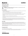
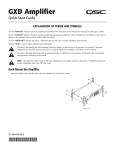
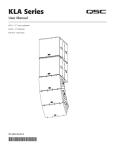
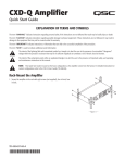
KLA181
Quick Start Guide
Rigging KLA Series Loudspeakers
WARNING!: Read and follow these instructions carefully. If the loudspeakers are not suspended properly, they could fall,
causing personal injury and damage to the equipment.
Rules for Suspension
• Consult a professional mechanical or structural engineer, licensed in the jurisdiction of the sound system installation, to review, verify, and approve
all attachments to the building or structure.
• Employ the services of a certified, professional rigger for hoisting, positioning, and attaching the equipment to the supporting structure.
• Correct use of all suspension hardware and components is imperative in sound system suspension and deployment.
• Always calculate suspended loads before lifting to make sure suspension components and hardware are used within their respective load limits.
• Consult local codes and regulations to fully understand the requirements for suspended loads in the venue in which you will suspend
the equipment.
• Use only the KLA AF12 Array Frame or the M10 installation points for suspending the array.
• Be absolutely certain of the integrity of any structural member intended to support suspended loads. Hidden structural members can have hidden
structural weakness.
• Never assume anything! Owner or third-party supplied suspension attachment points may not be adequate for suspending the loads.
• Before lifting, always inspect all components (enclosures, suspension brackets, pins, frames, bolts, nuts, slings, shackles, etc.) for cracks, wear,
deformation, corrosion, missing, loose, or damaged parts that could reduce the strength of the assembly. Discard any worn, defective, or suspect
parts and replace them with new appropriately load-rated parts.
Shock Loading
When a load is either moved or stopped, its static weight is magnified. Sudden movements can magnify the static weight several times. This
magnification of static weight is called "shock loading". Shock loading poses a danger to equipment and workers. The effects of shock loading can be
instantaneous, or may remain undetected unless the equipment is visually damaged. Proper preparation for shock loading requires careful planning
and knowledge of equipment, suspension, and lifting practices.
Shock loading of equipment and structures is usually confined to lifting and installation, but natural forces (winds, earthquakes, and so on) can impose
shock loads several times the static load. Because of this, structures and suspension equipment must be capable of supporting several times the
weight of the suspended equipment.
KLA Maximum Suspended Load
The KLA components are engineered for a 10:1 design factor. Use a KLA
AF12 Array Frame or the M10 Integrated Suspension points to suspend one
KLA Array consisting of one of the following array configuration options.
The maximum number of KLA12 Loudspeakers in any array, with or without
KLA181 Loudspeakers, is five.
TD-000335-00-C
*TD-000335-00*
Maximum Suspended Loudspeakers per Array
Array Configuration Option
A
B
C
Maximum Number of KLA181 Loudspeakers
2
3
4
Maximum Number of KLA12 Loudspeakers
5
3
0
— Table 1 —
Rigging KLA181 Loudspeakers Together
2
2
1
1
3
Retracted
Position
— Figure 1 —
Locked
Position
Up
Position
— Figure 2 —
1. Insert the supplied 6 mm hex key into the hex socket (Figure 1, 1) and make sure the hex key is rotated completely to the Unlock position.
2. Place a KLA181 on top of the first one with the loudspeakers facing the same direction. Make sure that the four feet (2) on the top KLA181 nest
properly with the four feet receptacles (3) on the top of the bottom KLA181.
NOTE: The bottom portion of Figure 2 shows the motion of the hook during the latching process. This is not visible on the
actual hardware.
3. Insert the 6 mm hex key into the hex socket (1) in the lower KLA181 and turn the key fully to the Locked Position. Repeat for the other side.
a. In the Retracted Position, you cannot see the hook in the view holes.
b. When the hook reaches the Up Position, the hook almost completely fills the large viewing (2) hole at the top.
c. In the final, Locked Position, you can see a small portion of the hook in the bottom of the large viewing hole (2).
Using Integrated Suspension Points
NOTE: The KLA181 suspension points are designed for use with the eyebolts (M10
X 1.50, 35 mm – 38 mm) included in the available accessory kit (model number:
KLA181 M10 KIT).
1. Use a 6 mm hex key to remove the four hex screws from the four KLA181 M10
installation points on the top of the loudspeaker.
2. Thread an eyebolt (1) into each of the threaded inserts.
3. Tighten the eyebolts until their shoulders are snug against the enclosure.
4. Continue to rotate the eyebolts until they reach the desired position. Do not overtighten.
— Figure 3 —
5. The loudspeakers are ready for suspension.
TD-000335-00-C
2
Rigging a KLA12 to a KLA181
The KLA12 cannot be rigged to the top of a KLA181.
There are various ways to facilitate rigging a KLA12 to a KLA181, and they vary depending on the specific circumstances. Be sure to use proper rigging
techniques, and/or employ a professional engineer. Following is one example.
Suspend the KLA181 as described in "Other KLA181 Deployment" on page 4, then carefully rig a KLA12
to the bottom of the KLA181 using the KLA12 rigging system. Continue rigging the remaining KLA12s to
the array.
1. Make sure that levers (1) and slides (2) (on both sides of the KLA12 loudspeaker), are in the positions
shown in Figure 5 "Retracted Position".
Refer to Figure 4.
2. Place the top of the KLA12 up to the bottom of the KLA181 such that the front feet on the KLA181 nest into
the feet receptacles on the top of the KLA12.
IMPORTANT: The front and sides of the KLA12 should be aligned flush with the
front and sides of the KLA181. When the front feet of the KLA181 are properly
nested into the feet receptacles of the KLA12, there will be no gap between the
two boxes.
— Figure 4 —
Refer to Figure 5
3. On the KLA12 loudspeaker with the hook (2) in the Retracted Position, push button "A" to release slide (1). Slide (1) automatically moves
upward, and the hook (2) automatically rotates to the Up Position. In the Up Position, the hook fills the view hole (3) in the KLA181.
4. On the KLA12 loudspeaker, pull lever "B" downward to lock the hook (2) in the Locked Position and secure the loudspeakers. When the hook (2)
is properly latched, you can only see a portion of the hook (2) through the view hole (3).
3
3
3
B
2
B
2
2
B
A
1
1
— Figure 5 —
WARNING!: Make sure that the lever "B" locks in the downward, Locked Position indicating that the hook itself is locked. If the
locking mechanism is not properly latched, the loudspeakers could separate and cause physical damage to the loudspeakers,
and/or personal injury.
5. Repeat the procedure for the other side of the loudspeakers, and for all KLA12 loudspeakers in the array. The loudspeakers are ready to suspend.
TD-000335-00-C
3
Other KLA Series Deployment Options
In addition to the M10 rigging listed above, you can use a KLA AF12 array frame to suspend an array (Figure 6), you can pole-mount up to two
KLA12s over a KLA181 (Figure 7).
Max pole length
36 inches
(914 mm)
— Figure 6 —
— Figure 7 —
Making Connections
AC Mains
Audio Source
ML
AO
X U
I D
MS
U P
ME
F
I
V
E
A
K
E
R
S
— Figure 8 —
WARNING!: Do not connect more than five KLA Series loudspeakers together using the loop-thru power cables (four loop-thru
cables, one AC power cord). Make all loop-thru connections prior to connecting to the AC mains.
CAUTION!: Do not restrict airflow to the rear of the speaker enclosure. Do not expose the rear panels exposed to a heat source such
as direct sunlight.
TD-000335-00-C
4
Mailing Address:
QSC Audio Products, LLC
1675 MacArthur Boulevard
Costa Mesa, CA 92626-1468 USA
Telephone Numbers:
Main Number: (714) 754-6175
Sales & Marketing: (714) 957-7100 or toll free (USA only) (800) 854-4079
Customer Service: (714) 957-7150 or toll free (USA only) (800) 772-2834
Facsimile Numbers:
Sales & Marketing FAX: (714) 754-6174
Customer Service FAX: (714) 754-6173
World Wide Web:
www.qscaudio.com
E-mail:
[email protected]
[email protected]
[email protected]
If you would like a full copy of the KLA Series User manual, visit the QSC Audio Products website
at www.qscaudio.com, or contact Customer Service +1 714 957-7150 or toll free (USA only)
(800) 772-2834 to receive a copy by mail.
Si desea obtener una copia completa del manual del usuario de la serie KLA, visite el sitio web
de QSC Audio Products en www.qscaudio.com, o póngase en contacto con el Servicio al Cliente
al +1 714 957-7150 o sin costo (sólo en EE.UU.) al (800) 772-2834 para recibir una copia
por correo.
Pour obtenir un exemplaire complet du manuel d’utilisation de la série KLA, allez sur le site Web
QSC Audio Products à www.qscaudio.com ou contactez le service clientèle au +1 714 957-7150
ou au (800) 772-2834 (numéro vert - USA seulement) pour recevoir un exemplaire par courrier.
Ein vollständiges Exemplar des Benutzerhandbuchs für die KLA-Serie finden Sie auf der QSC
Audio Products-Website unter www.qscaudio.com. Sie können sich unter +1 714 957-7150
oder unter der (nur in den USA) gebührenfreien Nummer +1 (800) 772-2834 auch an den
Kundendienst wenden, um sich ein Exemplar zuschicken zu lassen.
如果您需要 KLA 系列产品用户手册的完整副本,请访问 QSC 音频产品网站 www.qscaudio.
com,或致电客户服务部门 +1 714 957-7150,或拨打免费电话(仅限美国)(800) 772-2834 通
过邮件获取副本。
© 2011 QSC Audio Products, LLC. All rights reserved. QSC™ and the QSC logo are registered trademarks of QSC Audio Products, LLC in the U.S. Patent and Trademark office and
other countries. Tilt-Direct, Intrinsic Correction, DEEP and GuardRail are all trademarks of QSC Audio Products, LLC. powerCON is a registered trademark of Neutrik.
All other trademarks are the property of their respective owners. Patents may apply or be pending.
TD-000335-00-C
5