1
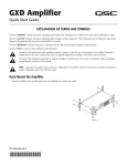
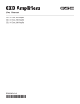
CXD-Q Amplifier
Quick Start Guide
EXPLANATION OF TERMS AND SYMBOLS
The term “WARNING!” indicates instructions regarding personal safety. If the instructions are not followed the result may be bodily injury or death.
The term “CAUTION!” indicates instructions regarding possible damage to physical equipment. If these instructions are not followed, it may result in
damage to the equipment that may not be covered under the warranty.
The term “IMPORTANT!” indicates instructions or information that are vital to the successful completion of the procedure.
The term "NOTE" is used to indicate additional useful information.
The intent of the lightning flash with arrowhead symbol in a triangle is to alert the user to the presence of un-insulated "dangerous"
voltage within the product's enclosure that may be of sufficient magnitude to constitute a risk of electric shock to humans.
The intent of the exclamation point within an equilateral triangle is to alert the user to the presence of important safety, and operating
and maintenance instructions in this manual.
NOTE: This Quick Start Guide is based on the basic configuration as the amplifier comes from the factory. For detailed instructions for
custom configurations refer to the CXD-Q User Guide (TD-000438).
Rack-Mount the Amplifier
1. Secure the amplifier in the rack with eight screws (not supplied), four in front, four
in back.
— Figure 1 —
TD-000437-00-A
*TD-000437-00*
Connections
LAN A LAN B
Q-Sys Q-LAN
Connect the amplifier LAN A, and if available, LAN B, to the Q-LAN network. (Figure 2) Refer to your Q-Sys documentation for
network requirements and connection detail.
— Figure 2 —
Unbalanced
Balanced
Inputs
The analog inputs are converted to digital audio in the CXD-Q amplifiers and then routed to the Q-Sys
Core over the network. The digital signals show up in Q-Sys Designer at the CXD-Q input component
where they can be routed as needed. Refer to the Q-Sys documentation.
—
1. Wire the audio line-level source to up to four Euro-style connectors (supplied). You may use either
balanced inputs (Figure 3) or unbalanced inputs (Figure 4).
2. Plug the connectors into the appropriate receptacles (Routable Inputs 1, 2, 3, 4) Figure 5.
WARNING!: Do not turn the amplifier on at this time.
+
+
—
— Figure 4 —
— Figure 3 —
ROUTABLE INPUTS
1
2
3
4
3. Connect the IEC power cord to the AC receptacle on the rear of the amplifier. (Figure 6)
GPIO
— Figure 5 —
Refer to "GPIO" on page 8 for details about using the GPIO.
1
2
3
4
5
6
7
8
Outputs and Configuration
The configuration of the amplifier and the amplifier component in the Q-Sys design file must match.
Double check that these are identical and if necessary change the configuration by following the
instructions on the front panel of the amplifier. When the output configuration of the amplifier
changes, the Outputs to the loudspeakers change accordingly. Use the diagrams shown in Figure
8 thru Figure 10 as a reference for wiring the loudspeakers. After connecting the outputs to the
loudspeakers, you may turn the amplifier on.
— Figure 6 —
9
10
11
12
13
14
15
16
— Figure 7 —
Figure 8 through Figure 11 are examples of the three types of output configurations: Separate, Bridged and Parallel. The tables to the right of the
loudspeaker connections give all the possible configurations and their connections.
Separate Channels (A B C D)
For Four Separate Loudspeakers
OUTPUTS TO SPEAKERS
Use four 2-wire cables, connect to:
• T1+/T2- (Loudspeaker 1)
• T3+/T4- (Loudspeaker 2)
• T5+/T6- (Loudspeaker 3)
• T7+/T8- (Loudspeaker 4)
CHANNEL CONFIGURATION
Q A
Q B
Q C
Q D
4 Channels: A B C D
Channel Configuration Locked to Design
— Figure 8 —
2
TD-000437-00-A
+
+
CH B
+
CH C
+
CH D
CH A
T1
T2
T3
T4
T5
T6
T7
T8
PARALLEL CHANNEL
COMBINING APPLICATIONS
SETTINGS CAN BE
CH AB
CONFIGURED FOR
T1+ T270V, 100V AND
T3+ T4200V DIRECT
OUTPUT.
BRIDGED
CH A+B
T1+ T3-
CH C+D
T5+ T7CH AB+CD
T1+ T5T3+ T7-
CH CD
T5+ T6T7+ T8CH ABC
T1+ T2T3+ T4T5+ T6CH ABCD
T1+ T2T3+ T4T5+ T6T7+ T8-
Bridged (A+B) and Separate (C D) Channels
For A+B (Bridged) One Loudspeaker
OUTPUTS TO SPEAKERS
Use one 2-wire cable connect to:
• T1+/T3-
+
+
CH B
+
CH C
+
CH D
CH A
For C & D (Separate) Two Loudspeakers
Use two 2-wire cables connect to:
• T5+/T6- for CH C
• T7+/T8- for CH D
CHANNEL CONFIGURATION
Q A+B
Q C
Q D
T1
T2
T3
PARALLEL CHANNEL
COMBINING APPLICATIONS
CH AB
SETTINGS CAN BE
T1+ T2CONFIGURED FOR
T3
+ T470V, 100V AND
200V DIRECT
OUTPUT.
BRIDGED
T4
CH A+B
T1+ T3-
T5
CH C+D
T5+ T7-
T6
CH AB+CD
T1+ T5T3+ T7-
T7
T8
CH CD
T5+ T6T7+ T8CH ABC
T1+ T2T3+ T4T5+ T6CH ABCD
T1+ T2T3+ T4T5+ T6T7+ T8-
3 Channels: A+B C D
Channel Configuration Locked to Design
— Figure 9 —
Parallel Channels (ABCD)
For One Loudspeaker
OUTPUTS TO SPEAKERS
Full power to one loudspeaker
Use one 2-wire cable, connect to:
• T1+/T2• Jumper T1, T3, T5, T7
• Jumper T2, T4, T6, T8
+
+
CH B
+
CH C
+
CH D
CH A
For Multiple Loudspeakers
Full power for multiple loudspeakers in parallel
Use up to four 2-wire cables, connect to:
• T1+/T2CHANNEL CONFIGURATION
• T3+/T4• T5+/T6Q ABCD
• T7+/T81 Channel: A B C D
Channel Configuration Locked to Design
T1
T2
T3
SETTINGS CAN BE
CONFIGURED FOR
70V, 100V AND
200V DIRECT
OUTPUT.
T4
T5
T6
T7
T8
T1+, T3+, T5+, and T7+ are electrically the same point
T2-, T4-, T6-, and T8- are electrically the same point
— Figure 10 —
Connect the Loudspeakers
1. Connect the loudspeaker wiring to the 8-pin Euro-style connector as needed for
your amplifier's configuration.
2. Install the female 8-pin Euro-style connector onto the male connector on the rear of
the amplifier as shown in Figure 11.
3. Use a Phillips screwdriver to secure the connector.
— Figure 11 —
3
TD-000437-00-A
BRIDGED
CH A+B
T1+ T3-
CH C+D
T5+ T7CH AB+CD
T1+ T5T3+ T7-
PARALLEL CHANNEL
COMBINING APPLICATIONS
CH AB
T1+ T2T3+ T4CH CD
T5+ T6T7+ T8CH ABC
T1+ T2T3+ T4T5+ T6CH ABCD
T1+ T2T3+ T4T5+ T6T7+ T8-
Amplifier Control
NOTE: The following scenarios assume that the amplifier
is connected to the Q-Sys Core via Q-LAN. When the
amplifier is not connected to the Q-Sys Core, it is in a Fault
mode, and not operational.
Off Mode
• Rear power switch is off, the amplifier is not operable. The power
switch is the AC Mains disconnect.
Master Control Knob
• Adjusts the Gain for the selected channel or channels. At least one
channel must be selected.
• When one or more channels are selected, turn the Master Control
knob to jump to the Gain screen. After a few seconds with no activity,
it returns to the earlier screen.
• If there is more than one channel selected, and the gains for those
channels are different, the difference is maintained unless the gain is
raised or lowered to the limits for both channels.
• The power button is not illuminated.
• Turn the power switch to on. The amplifier enters the mode in which
it was when power was removed – Run, Mute All, or Standby.
Run Mode
• From Standby or Mute All mode, press and release the power button
on the front panel. The amplifier is in Run Mode.
• The power button is illuminated green.
• The amplifier is fully operable; audio can pass.
Standby Mode
• From Mute All or Run mode, press and hold the power button on
the front panel for approximately four seconds.
• The power button illuminates solid red.
• The amplifier is not operable; audio will not pass.
Mute All Mode
• From the Run Mode, quickly press and release the power button.
• The power button flashes red, all output Mute buttons are red.
• The amplifier output is disabled, but the front panel is fully operable.
4
TD-000437-00-A
NEXT and PREV Buttons
NEXT
PREV
• Navigates forward and
backwards through the screens.
ID Button
ID
• Press this button to display a
screen with the amplifier's network name. In addition, the ID buttons
on the associated Q-Sys Amplifier component and the associated
Q-Sys Configurator item flashes. Press again, or click one of the other
ID buttons, to stop the flashing and exit the screen.
• When prompted, press this button to change the amplifier
configuration to match the configuration of the associated
Q-Sys design.
SEL Buttons
SEL
• Use these buttons to select an output channel in order to change
the Gain.
• Select more than one channel to change multiple gain settings at the
same time.
• If two or more outputs are bridged or in parallel, pressing one button
in the group selects all channels in that bridged or parallel group.
Inputs and Outputs
The CXD-Q amplifiers have four Mic/Line Inputs and four amplified Outputs on the rear of the amplifier. The Inputs and Outputs on the rear of the
amplifier are not connected inside the amplifier.
The analog inputs are converted to digital audio in the CXD-Q amplifiers and then routed to the Q-Sys Core via Q-LAN (LAN A, LAN B). The digital
signals are brought into the design in the CXD-Q Amplifier Input component. From the CXD-Q Input component the signals can be sent anywhere
within the system.
Likewise, in Q-Sys Designer digital signals are received at the CXD-Q Output component and fed from the Q-Sys Core to the analog amplified outputs
of the CXD-Q via Q-LAN. The CXD-Q output component can have one to four outputs depending on the configuration of the amplifier. The desired
configuration is selected in the properties menu for that amplifier. Use the ID button on the front panel of the amplifier to accept the configuration.
+
+
CH B
+
CH C
+
CH D
-
T1
CH A
ROUTABLE INPUTS
1
2
3
4
Q-LAN
CXD4.3Q In
cxq-1234
Q-Sys
DSP, Routing,
and so on.
CXD4.3Q Out
cxq-1234
CXD-Q Input
Component
Q-LAN
CXD-Q Output
Component
T2
T3
T4
T5
T6
T7
T8
— Figure 12 —
Screens
CHANNEL CONFIGURATION
Channel Configuration Screens
1. Graphic representations of the amplifier's output configuration. Inputs (Q) are from Q-Sys, 1
outputs (A-D) show the amplifier channels and their configuration.
2. Text indicating how many channels, and the output configuration. For possible
configurations refer to the Q-Sys help for the CXD-Q Amplifier component.
Q A
Q C
Q D
4 Channels: A B C D
2
3
Q B
Channel Configuration Locked to Design
3. Status of the amplifier and Q-Sys design indicating the design and amp are in synch.
4. Status of the amplifier indicating that action is necessary to synchronize the design and
amplifier.
CHANNEL CONFIGURATION
4
5. Action you need to perform to change the amplifier configuration. Press the ID button to
the right of the message.
Status Screen
Design requires 3 Channels: A+B C D
Q A
Press ID to Accept
— Figure 13 —
3. STATUS: Displays the current status of the amplifier both in text and color. The following is 1
2
a list of possible status colors, and some example conditions.
5
DEVICE:
STATUS
CXQ-1234
DESIGN:
My Design Filename
• OK – Green – Audio is good, hardware is good.
3
STATUS:
• Compromised – Orange – Audio is good but a redundancy mechanism is active (one
LAN down but the other is still up) or a non-fatal hardware problem exists (fans too
slow, temperature higher than expected, etc.)
4
FIRMWARE:
TD-000437-00-A
Q D
4 Channels: A B C D
2. DESIGN: This is the name of the Q-Sys design containing the amplifier. The amplifier must
be in a running design to operate.
• Initializing – Blue – In the process of initialization, and design start. Audio is not passed.
Q C
5
1. DEVICE: This is the hostname (network name) of the amplifier. A default name is given at
the factory, similar to the example. You may change the name in the Q-Sys Configurator.
• Fault – Red – Audio is not passing, or hardware is malfunctioning or mis-configured
(amplifier power off, audio streams broken, amplifier fault, loudspeaker short circuit,
etc.)
Q B
5
OK
4.0.00
GAIN AB: -27.0 dB
6
— Figure 14 —
GAIN C:
0 dB
GAIN D:
10.0 dB
4. FIRMWARE: The Q-Sys Designer firmware version. To update the firmware:
a.
b.
c.
d.
The version you want to use must be installed on your PC,
The amplifier must be connected to the network, and turned on.
Open the Q-Sys design containing the amplifier and select "Save to Core and Run" from the File menu.
The amplifier Q-LAN processor and any other Q-Sys peripherals in the design are automatically updated.
5. GAIN A - D: Displays the current Gain setting for each channel. If channels are combined, they are displayed together. The green background gives
a graphical indication of the Gain.
LAN A
LAN A / LAN B Screen
1. Default IP Address. You can change this and the other parameters in Q-Sys Configurator.
LAN A is required, and cannot be turned off.
1
2
3
IP ADDRESS:
192.168.xxx.xxx
NETMASK:
255.255.0.0
GATEWAY:
0.0.0.0
LAN B
4
IP ADDRESS:
2. Default Netmask.
NETMASK:
3. Default Gateway.
GATEWAY:
4. LAN B is not required, as indicated by empty fields in Figure 15.
— Figure 15 —
Health Screen
1. FAN Speed – varies depending on the temperature.
2. TEMP – three different temperatures, are monitored and automatically put the amplifier
into limiting or shutdown if the limits below are exceeded.
HEALTH
FAN:
1
2
• Thermal Limiting starts at 69ºC
35.3°C
CH A&C Temp:
35.4°C
CH B&D Temp:
35.3°C
• Thermal Shutdown at 80ºC
3. Voltage Rails
1109
PSU TEMP:
3
VRAIL 1:
149
VRAIL 2:
-151
• VRail 1 = +147VDC +/- 5V typical
— Figure 16 —
• VRail 2 = -147VDC +/- 5V typical
Output Screens
Each output or group of outputs has a dedicated screen. Figure 17 is an example of Output A.
1. GAIN – The amount of gain applied to the input signal. Controlled by the GAIN knob on
the front panel of the amplifier, or the GAIN control in the CXD-Q Output component in
the Q-Sys Design.
2. INPUT – The level of the audio signal applied to the CXD-Q Output component in the
Q-Sys design. The CXD-Q Output component is the connection to the output section of
the amplifier. This meter reading can be changed from RMS to Peak in the Amplifier Out
component in the Q-Sys design.
OUTPUT A
1
GAIN:
-23.0 dB
2
Q-LAN INPUT:
-45.0 dB
3
VOLTAGE:
.777 V
4
POWER:
.011 W
5
HEADROOM:
3. VOLTAGE - The voltage being delivered to the loudspeaker. This reading can be RMS or
Peak depending on the Meter Select setting in the Q-Sys design for the associated channel.
-41.3 dB
DAC LIMIT
PROTECT
CLIP
LIMIT
6
7
8
9
— Figure 17 —
4. POWER – The power of the amplifier / loudspeaker circuit. This reading can be RMS or
Peak depending on the Meter Select setting in the Q-Sys design for the associated channel.
5. HEADROOM – The amount of room left before reaching the amplifier's maximum capabilities.
6. DAC LIMIT – When illuminated, this indicates that the signal to the D to A Converter is larger than can be reproduced and a limiter has been
engaged to prevent clipping. This is an indication that the gain structure is not correct.
7. PROTECT – When illuminated, this indicates that the channel is in Protect Mode. Usually due to driving too low of an impedance for too long.
8. LIMIT – When illuminated, this indicates the amplifier limiter is active. This occurs if the signal is driving the power, current, or voltage above the
amplifier rated values or due to thermal limiting.
6
TD-000437-00-A
Output Gains Screen
1
2
The Output Gains screen provides a quick overview of all outputs and is the screen on which
GAIN adjustments are made.
Use the NEXT or PREV buttons to access this screen or, press one or more of the SEL buttons
to access the screen and make GAIN adjustments for the selected channels. If you press one
or more of the SEL buttons, and do not make any GAIN adjustments, this screen remains
visible for a short time the returns to the previous screen.
1. The highlighted background indicates that the Channel is selected by the SEL button.
3
OUTPUT GAINS
AB
-45.0 dB
Q-LAN:
-8.08 dB
VOLTS:
101 V
6
C
D
-45.0 dB
-45.0 dB
Q-LAN:
-100.0 dB
VOLTS:
.014 V
Q-LAN:
-100 dB
VOLTS:
.014 V
2. Channel – the channels display according to the configuration of the amplifier.
3. Output Gain – the output gain is controlled by the GAIN knob on the amplifier or with the
Gain control in the CXD-Q Output component in the Q-Sys design.
— Figure 18 —
4. Q-LAN Input Level – the level of the audio signal applied to the CXD-Q Output component in the Q-Sys design. The CXD-Q Output component is
the connection to the output section of the amplifier.
5. Voltage – The voltage applied to that output.
6. Output B is combined with Output A, the slot for Output B is removed.
7
TD-000437-00-A
4
5
GPIO
Connector
Pin
GPIO # and
Function
Specifications
1
3.3 V
100 mA max (power cycle to reset current limiting IC)
2
GPIO 1
5mA in/out, 3.3V max, 127 Ohm resistor in series
3
GPIO 2
5mA in/out, 3.3V max, 127 Ohm resistor in series
4
GND
Ground
5
GPIO 3
5mA in/out, 3.3V max, 127 Ohm resistor in series
6
GPIO 4
5mA in/out, 3.3V max, 127 Ohm resistor in series
7
GND
Ground
8
GPIO 5
18mA in/out max, 3.3V max, 127 Ohm resistor in series
9
RELAY NO
Relay Normally Open
10
RELAY COM
Relay Common
11
RELAY NC
Relay Normally Closed
12
GND
Ground
13
GPIO 6
18mA in/out max, 3.3V max, 127 Ohm resistor in series
14
GPIO 7
18mA in/out max, 3.3V max, 127 Ohm resistor in series
15
GND
Ground
16
GPIO 8
18mA in/out max, 3.3V max, 127 Ohm resistor in series
1
2
3
4
5
6
7
8
9
10
11
12
13
14
15
16
— Figure 19 —
Examples
Button or Contact Closure
GPIO
Potentiometer
Ground
— Figure 20 —
8
TD-000437-00-A
GPIO 5-8
+3.3 V
GPIO
Analog In
Ground
Q-Sys-Powered LED
10 kΩ
Ground
Works for LEDs up to 18 mA.
Current is limited in the GPIO circuit
by a 127Ω resister in series.
Contact
Support
Mailing Address
24/7 Support
QSC Audio Products, LLC
1675 MacArthur Boulevard
Costa Mesa, CA 92626-1468 U.S.
Main Number
(714) 754-6175
World Wide Web
www.qscaudio.com
Sales & Marketing
Voice
(714) 957-7100 International
Toll free (U.S. only) (800) 854-4079
QSC offers 24/7 support on Q-Sys™
Networked Audio Systems only.
Q-Sys™ Customer Support
Full Support for all QSC Products
Business Hours: 6 AM to 5 PM Pacific Time (Mon-Fri)
Tel. 800-772-2834 (U.S. only)
Tel. +1 (714) 957-7150
Fax. +1 (714) 754-6173
Q-Sys Emergency-only After-Hours and Weekend Support*
Tel: +1-888-252-4836 (U.S./Canada)
Tel: +1-949-791-7722 (non-U.S.)
* After hours calls are guaranteed a 30 minute response time from a
Q-Sys Support Team member. For Q-Sys ONLY!
E-mail
[email protected]
FAX
(714) 754-6174
E-mail
(An immediate e-mail response is not guaranteed. For URGENT issues
use the phone numbers above.)
[email protected]
If you would like a full copy of the CXD-Q User manual, visit the QSC Audio Products website at www.qsc.com, or contact
Customer Service +1 714 957-7150 or toll free (USA only) (800) 772-2834 to receive a copy by mail.
Si desea obtener una copia completa del manual del usuario de la CXD-Q, visite el sitio web de QSC Audio Products en
www.qsc.com, o póngase en contacto con el Servicio al Cliente al +1 714 957-7150 o sin costo (sólo en EE.UU.) al (800)
772-2834 para recibir una copia por correo.
Pour obtenir un exemplaire complet du manuel d’utilisation de la CXD-Q, allez sur le site Web QSC Audio Products à www.
qsc.com ou contactez le service clientèle au +1 714 957-7150 ou au (800) 772-2834 (numéro vert - USA seulement) pour
recevoir un exemplaire par courrier.
Ein vollständiges Exemplar des Benutzerhandbuchs für die CXD-Q finden Sie auf der QSC Audio Products-Website unter
www.qsc.com. Sie können sich unter +1 714 957-7150 oder unter der (nur in den USA) gebührenfreien Nummer +1 (800)
772-2834 auch an den Kundendienst wenden, um sich ein Exemplar zuschicken zu lassen.
如果您需要 CXD-Q 产品用户手册的完整副本,请访问 QSC 音频产品网站 www.qsc.com,或致电
客户服务部门 +1 714 957-7150,或拨打免费电话(仅限美国)(800) 772-2834 通过邮件获取副
本。
© 2014 QSC Audio Products, LLC. All rights reserved. QSC and the QSC logo are registered trademarks of QSC Audio Products, LLC in the U.S. Patent and Trademark office and
other countries. All other trademarks are the property of their respective owners.
http://patents.qsc.com.
9
TD-000437-00-A