1
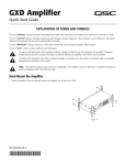
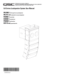
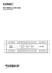
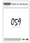
PLD Amplifier
Quick Start Guide
EXPLANATION OF TERMS AND SYMBOLS
The term “WARNING!” indicates instructions regarding personal safety. If the instructions are not followed the result may be bodily injury or death.
The term “CAUTION!” indicates instructions regarding possible damage to physical equipment. If these instructions are not followed, it may result in
damage to the equipment that may not be covered under the warranty.
The term “IMPORTANT!” indicates instructions or information that are vital to the successful completion of the procedure.
The term "NOTE" is used to indicate additional useful information.
The intent of the lightning flash with arrowhead symbol in a triangle is to alert the user to the presence of un-insulated "dangerous"
voltage within the product's enclosure that may be of sufficient magnitude to constitute a risk of electric shock to humans.
The intent of the exclamation point within an equilateral triangle is to alert the user to the presence of important safety, and operating
and maintenance instructions in this manual.
NOTE: This Quick Start Guide is based on the basic configuration as the amplifier comes from the factory. Four separate inputs, and
four separate outputs. For detailed instructions for custom configurations refer to the PLD User Guide (TD-000368).
Rack-Mount the Amplifier
1. Secure the amplifier in the rack with eight screws (not supplied), four in front,
four in back.
— Figure 1 —
TD-000351-00-B
*TD-000351-00*
1
Connections
Inputs
1. Wire the audio line-level source to four male XLR connectors. You may use either
balanced inputs (Figure 2) or unbalanced inputs (Figure 3).
2. Plug the male XLR connectors into the appropriate receptacles (Routable Inputs 1,
2, 3, 4) Figure 4. If you are daisy-chaining inputs with another amplifier, plug the
female XLR connectors, from the other amplifier, into the XLR's on the bottom row
of the Routable Inputs.
— Figure 2 —
— Figure 3 —
— Figure 4 —
3. Connect the IEC power cord to the AC receptacle on the rear of the amplifier. (Figure 5)
WARNING!: Do not turn the amplifier on at this time.
— Figure 5 —
Outputs
When the output configuration of the amplifier changes, the Outputs to the loudspeakers change accordingly. Connect the loudspeakers to the NL4
twist-lock connectors as shown in Figure 6 thru Figure 8. After connecting the Outputs to the Loudspeakers, you may turn the amplifier on.
Separate Channels (A B C D)
For Four Separate Cables
Use four 2-wire cables, connect to:
• 1+/1- on connectors #1 thru #4
For Bi-amp Operation
1
2
5
3
4
6
Use two 4-wire cables, connect to:
• 1+/1- for CH A and 2+/2- for CH B
on connector #1
• 1+/1- for CH C and 2+/2- for CH D
on connector #3
A
B
C
D
8.0 8.0 8.0 8.0
625 625 625 625
625 625 625 625
— Figure 6 —
2
Bridged (A+B) and Separate (C D ) Channels
For A+B (Bridged)
Use one 2-wire cable connect to:
• 1+/1- on connector #5
For C & D (Separate)
Use two 2-wire cables connect to:
• 1+/1- for CH C on connector #3
•1+/1- for CH D on connector #4
Bi-amp operation, use one 4-wire cable connect to:
• 1+/1- for CH C on connector #3
• 2+/2- for CH D on connector #3
A+B
C
D
A+B
8.0
8.0
8.0
8.0
8.0
1250
625
625
1250
1250
1250
625
625
1250
1250
1
2
5
3
4
6
C+D
— Figure 7 —
Parallel Channels (ABCD)
For Multiple Loudspeakers
Full power for multiple loudspeakers in parallel
Use up to four 2-wire cables, connect to:
• 1+/1- on connectors #1 thru #4
1
2
5
3
4
6
For One Loudspeaker
Full power to one loudspeaker
Use one 2-wire cable, connect to:
• 1+/1- on connector #1, #2, 3#, or #4
ABCD
8.0
2500
2500
— Figure 8 —
PLD Amplifier Signal Flow
Output Processing
Input Settings
Amp Configuration
Sensitivity
Switch
Meter
Gain
1
Source
Select
Mute
Highpass
Filter
Gain /
Polarity
Lowpass
Filter
5-band
PEQ
Delay
RMS / Peak
Limiter
Meter
A
Sensitivity
Switch
Meter
Gain
2
Source
Select
Mute
Highpass
Filter
Gain /
Polarity
Lowpass
Filter
5-band
PEQ
Delay
RMS / Peak
Limiter
Meter
B
Sensitivity
Switch
Meter
Gain
3
Source
Select
Mute
Highpass
Filter
Gain /
Polarity
Lowpass
Filter
5-band
PEQ
Delay
RMS / Peak
Limiter
Meter
C
Sensitivity
Switch
Meter
Gain
4
Source
Select
Mute
Highpass
Filter
Gain /
Polarity
Lowpass
Filter
5-band
PEQ
Delay
RMS / Peak
Limiter
Meter
D
Button
Actuated
Crossover
— Figure 9 —
3
Set by Wizard
Amplifier Control
ENTER Button
Off Mode
• Navigates into the menu structure
• Enters the edit mode for adjusting parameters
• Confirms the changes you make
• Rear power switch is off, the amplifier is not operable. The power
switch is the AC Mains disconnect.
• The power button is not illuminated.
• Turn the power switch to on. The amplifier enters the Run Mode.
• The power button is illuminated blue.
EXIT Button
ENTER
EXIT
• Navigates out of the menu structure and parameter selection.
• In the edit mode, pressing EXIT reverts the value back to its prior
state, and exits the edit mode.
Run Mode
HOME Button
• From Standby or Mute All modes, press and release the power button
on the front panel.
• The power button is illuminated blue.
• The amplifier is fully operable; audio can pass.
• If you are on the Home screen, pressing HOME displays the alternate
Home screen. Pressing HOME again returns you to the primary
Home screen.
• If you are on a navigation screen, pressing HOME takes you to the
home screen.
• If you are on an edit screen, pressing HOME will confirm any value
being edited and take you to the Home screen.
Standby Mode
• From Mute All or Run modes, press and hold the power button on
the front panel.
• The power button illuminates solid red.
• The amplifier is not operable; audio will not pass.
GAIN Button
HOME
GAIN
• Pressing the GAIN button from any screen takes you to the output
gain screen for the most recently accessed output channel.
• Pressing GAIN again confirms the gain change and returns to the
screen you were on when you pressed GAIN.
Mute All Mode
• From the Run Mode, press and release the power button.
• The power button flashes red.
• The front panel and DSP functionality are fully operable. Any changes
you make are saved and take effect in the Run Mode.
SEL Buttons
SEL
• Use these buttons to navigate between input channels or output
channels. For example, if you are adjusting output gain on channel A,
pressing the channel B SEL button takes you to the gain adjustment
for channel B.
• The SEL buttons are active only when the LCD screen is on an input
or output parameter adjustment screen.
Master Control Knob
• Scrolls up/down and right/left to select menu items and parameters
• Adjusts parameters
Menu Tree
Presets
Inputs
Outputs
Utilities
Preset Recall
Input Sensitivity
Source Select
Status
Preset Save
Input Gain
Processing
Amp ID
Preset Wizard
Array Correction*
Display
Crossover
Lockout
PEQ
Password
Delay
Limiter
Load Speaker
*For QSC Line Arrays only
Save Speaker
— Figure 10 —
4
Screen Types
Informational
Informational screens, like the HOME screen, are
designed to provide you with a good amount of
useful information at a glance.
Preset # and Configuration
Location and breadcrumbs
F1: Config - A B C D
Home (Press HOME for more information)
Full
Full
Full
Full
A - FR
+1.5 dB
B - FR
+3.5 dB
C - FR
+1.5 dB
D - FR
+1.5 dB
AC Voltage: 121 V
Channel Configuration
and Gain
AC Voltage and Current
AC Current: 7.2 A
Amplifier Status
Amp Status: OK
— Figure 11 —
Navigational
Navigational screens provide the means to move
around and select menu items. Use the Master
Control knob, ENTER and EXIT buttons for navigation.
This is an example of one type of navigational screen,
there are others.
Preset # and Configuration
Location and breadcrumbs
F1: Config - A B C D
Menu
Empty area indicates no
selections above (CCW).
PRESETS
Current Menu Selection
Preset Recall and Save
Next Menu selection below
(CW)
INPUTS
— Figure 12 —
Parameter Editing
F1: Config - A B C D
Output
A
20 dB
Parameter Editing screens allow you to select, edit,
and confirm changes for various system parameters.
Use the ENTER button to edit and confirm changes
to parameters. Use the Master Control knob to select
parameter, and make adjustments. Use the EXIT
button to exit the edit mode without saving changes.
Parameter being edited
Parameter not selected
Parameter selected
-60 dB
Gn/Pol
Gain
-7.0 dB
Polarity
POL+
Gain
-7.0 dB
— Figure 13 —
Presets
The PLD amplifiers are preset driven, so to get the most out of the amplifiers an understanding of how presets work is essential. A Preset, in the
context of the PLD amplifiers, is a combination of amplifier configuration and DSP processing; as a preset is recalled it can change the output routing
and wiring and/or any DSP processing.
Preset Creation
A preset can be created in two ways, the first is to modify an existing preset, then save this as a new Preset; the second is to use the Preset Wizard to
create a Preset from scratch.
Preset Wizard
The Preset Wizard simplifies the preset creation process, and allows the user to create a preset from the ground up. The Wizard provides a mechanism
for the user to select his desired power and load. Based on these selections, the best amplifier configuration is selected and the user is then allowed to
select and assign loudspeakers to each output.
5
To start the Wizard: HOME > PRESETS > PRESET WIZARD > ENTER
STEP 1 — Adjust Impedance and Power
OUTPUTS
SPEAKERS
SAVE
Output:
A
B
C
D
Imped:
8.0
--
--
--
Default = 8 Ω
Power:
25
--
--
--
Default = min. for amp
Adjust Impedance
Adjust Power
To confirm, press
ENTER
Remaining Power Available: 1875 W
Adjust Impedance based on the total loudspeaker load connected to the channel.
Enter Load Profile (Impedance and Power)
Possible Output Mode Combinations using the Preset Wizard
A
B
C
D
A+B
C
D
A+B
C+D
AB+CD
ABCD
8.0
8.0
8.0
8.0
8.0
8.0
8.0
8.0
8.0
8.0
8.0
1250
625
625
1250
1250
2475
2500
625 625 625 625
Modes:
A B = Separate Channels
A+B = Bridge Mode
AB = Parallel Mode
— Figure 14 —
STEP 2 — Select Output Channel for Speaker Assignment
OUTPUTS
SPEAKERS
SAVE
Output:
A
B
C
D
Imped:
8.0
8.0
8.0
8.0
Power:
625
625
625
625
Spkr:
----
----
----
----
Assign
Assign
Assign
Assign
Optional: Scroll to desired Output channel
To Assign a loudspeaker, press
ENTER
Loudspeaker assignment is optional.
STEP 3 — Select Speaker Type for Channel
OUTPUTS
SPEAKERS
A
Output:
Speaker:
To edit Speaker, press
SAVE
ENTER
Scroll to select Speaker type
WL2102 BiLFNS
Band:
2-Way LF
Filter:
80 Hz
Band and Filter
selections are based
on the Speaker.
CONFIRM
To exit edit mode and confirm, press
ENTER
Scroll to edit Band then Filter
STEP 4 — Save Wizard Preset
OUTPUTS
SPEAKERS
SAVE
Scroll to the Save screen
User Preset Number:
21
To edit User Preset number, press
New Preset Name
C
o
n
f
i
g
-
A
To name and save the preset,
Complete steps 1 thru 3 under
“To Save a New User Preset”
SAVE
Edit preset number or press EXIT
6
ENTER
Saving Presets
Presets can be modified and saved using the Save Preset menu. You can start with a Factory Preset (F<n>: <name>), make modifications, then save
it as a User Preset (U<n>: <name>). You cannot overwrite Factory Presets. There are two ways to save Presets, Overwrite an existing User Preset, or
Save a new User Preset.
To Overwrite a User Preset, HOME > PRESETS > PRESET SAVE > ENTER
Overwrite Preset
U1: Config - A B C D
To save, press
SAVE
To exit without saving, press
To confirm the save, press
ENTER
EXIT
ENTER
Press ENTER to save preset
To Save a New User Preset, HOME > PRESETS > PRESET SAVE AS > ENTER
STEP 1 — Select and Edit Preset Number
U1: Config - A B C D
User Preset Number:
21
To edit User Preset number, press
A
Scroll to desired number (1 thru 50)
ENTER
New Preset Name
C
o
n
f
i
g
-
SAVE
To confirm User Preset number, press
ENTER
Edit preset number or press EXIT
STEP 2 — Name the Preset
U1: Config - A B C D
User Preset Number:
Indicates editing
Indicates New Preset
Name selection
21
New Preset Name
C
o
n
f
i
g
X
Indicates more positions
A
SAVE
Scroll to New Preset Name
Press
Scroll to desired position
Press
Press ENTER to edit preset name
ENTER
ENTER
Up to 21 characters, A - Z / a - z / 0 - 9 / _ / - / space
STEP 3 — Save Preset
U1: Config - A B C D
When you are finished naming, press
User Preset Number:
21
Scroll to SAVE
New Preset Name
C
o
n
f
i
g
EXIT
X
A
Press
ENTER
To confirm Save, press
ENTER
SAVE
Press ENTER to save preset
7
Recalling Presets
Recalling a Preset changes the configuration of the amplifier. You can recall factory or user-defined presets. To Overwrite a User Preset,
HOME > PRESETS > PRESET RECALL > ENTER
STEP 4 —
F1: Config - A B C D
Indicates more Presets
F1: Config - A B C D
Full
Full
1 A
Input
Full
2 B
Sub
LF
Full
3 C
MF
Scroll to desired Preset
20 Factory, up to 50 User-defined
4 D
HF
Full
STEP 5 — Confirm Selection
F1: Config - A B C D
F18: Triamp - A+B C D
LF
MF
HF
1 A+B
3 C
4 D
Press ENTER to confirm selection
To select the Preset configuration, press
ENTER
To Confirm the selection, press
ENTER
Bottom message changes to: “Recalling Preset now...”
You may hear relays clicking
Utilities
The Utilities section provides the following amplifier information and functionality:
• STATUS
• ID
• Serial Number
• LOCKOUT
• PASSWORD.
Please refer to the PLD User Manual for complete details.
8
Mailing Address:
QSC Audio Products, LLC
1675 MacArthur Boulevard
Costa Mesa, CA 92626-1468 USA
Telephone Numbers:
Main Number: (714) 754-6175
Sales & Marketing: (714) 957-7100 or toll free (USA only) (800) 854-4079
Customer Service: (714) 957-7150 or toll free (USA only) (800) 772-2834
Facsimile Numbers:
Sales & Marketing FAX: (714) 754-6174
Customer Service FAX: (714) 754-6173
World Wide Web:
www.qsc.com
E-mail:
[email protected]
[email protected]
[email protected]
If you would like a full copy of the PLD User manual, visit the QSC Audio Products website at www.qsc.com, or contact
Customer Service +1 714 957-7150 or toll free (USA only) (800) 772-2834 to receive a copy by mail.
Si desea obtener una copia completa del manual del usuario de la PLD, visite el sitio web de QSC Audio Products en www.
qsc.com, o póngase en contacto con el Servicio al Cliente al +1 714 957-7150 o sin costo (sólo en EE.UU.) al (800) 772-2834
para recibir una copia por correo.
Pour obtenir un exemplaire complet du manuel d’utilisation de la PLD, allez sur le site Web QSC Audio Products à www.
qsc.com ou contactez le service clientèle au +1 714 957-7150 ou au (800) 772-2834 (numéro vert - USA seulement) pour
recevoir un exemplaire par courrier.
Ein vollständiges Exemplar des Benutzerhandbuchs für die PLD finden Sie auf der QSC Audio Products-Website unter www.
qsc.com. Sie können sich unter +1 714 957-7150 oder unter der (nur in den USA) gebührenfreien Nummer +1 (800) 7722834 auch an den Kundendienst wenden, um sich ein Exemplar zuschicken zu lassen.
如果您需要 PLD 产品用户手册的完整副本,请访问 QSC 音频产品网站 www.qsc.com,或致电客户服
务部门 +1 714 957-7150,或拨打免费电话(仅限美国)(800) 772-2834 通过邮件获取副本。
© 2013 QSC Audio Products, LLC. All rights reserved. QSC and the QSC logo are registered trademarks of QSC Audio Products, LLC
in the U.S. Patent and Trademark office and other countries.
All other trademarks are the property of their respective owners. Patents may apply or be pending.
9