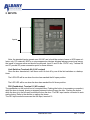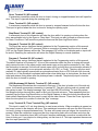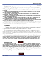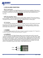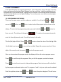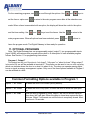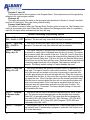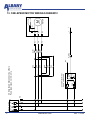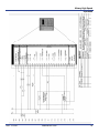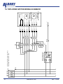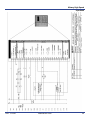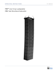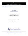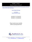
1
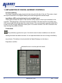
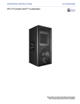
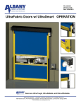
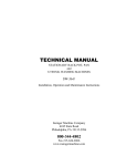
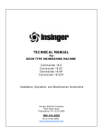
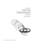
High Performance Doors Digital Gateway User’s Manual 1080 Maritime Drive, Port Washington, WI 53074 975A Old Norcross Road, Lawrenceville, GA 30045 STATEMENT OF WARRANTY UltraSeries™ ONE-YEAR WARRANTY ON MECHANICAL AND ELECTRICAL COMPONENTS Albany Door Systems warrants to the original owner of the door that the mechanical and electrical components will be free from defects in material and workmanship for a period of one (1) year from the date of shipment. The warranty does not cover fuses, bolts, heat lamps, sleeves, and seals. The warranty is void twelve (12) months following the shipment date of the door.` Only defects brought to the attention of Albany Door Systems during the warranty period will be covered by this warranty. Albany Door Systems will replace component parts covered by this warranty, which are found to be defective upon inspection by an Albany Door Systems representative. Installation or use of parts other than those authorized by Albany Door Systems will void this warranty. This warranty covers material failure under normal wear conditions; it does not cover damage caused by collision or other abuse of the product. Adjustments made to the control panel or to the mechanical operation of the door without the authorization of Albany Door Systems will void this warranty. PARTS AND ASSEMBLIES sold separately by Albany Door Systems that fail due to defects in material or workmanship within ninety (90) days from the date of shipment will be replaced under warranty provided installation has been carried out in accordance with all Albany Door Systems procedures. This warranty is limited to providing a replacement part only. This warranty does not cover freight, special charges, or any costs associated with the installation of the replacement part. This warranty shall be void in its entirety if the failure of any product shall be caused by any installation, operation, or maintenance of the product which does not conform with the requirements set forth by the seller in the applicable product manuals or is in the result of any cause other than a defect in the material or workmanship of the product. Albany Door Systems shall not be responsible for any other losses or damages due to the operation of any door or parts covered by this warranty. No other oral or written representation made by Albany Door Systems or its agents are a part of this THE ABOVE SET FORTH WARRANTY IS SELLER’S SOLE WARRANTY. SELLER MAKES NO OTHER WARRANTY OF ANY KIND WHATSOEVER, EXPRESSED OR IMPLIED; AND ALL IMPLIED WARRANTIES OR MERCHANTABILITY AND FITNESS FOR A PARTICULAR PURPOSE WHICH EXCEED THE AFORESTATED OBLIGATION ARE HERBY DISCLAIMED BY SELLER AND EXCLUDED FORM THIS AGREEMENT. 1 Manual #001445 Rev. 1/12/09 Albany High Speed Operation TABLE OF CONTENTS Explanation of Digital Gateway Controls 3 Inputs 5 Timers 8 Start-Up Procedures 9 Alarm Conditions 10 Non-Alarm Conditions 11 Power 11 Outputs 11 Replacement 12 Program Options 12 Optional Programs 13 Control Panel Layout 16 One-Speed Motor Wiring Schematic 17 Two-Speed Motor Wiring Schematic 19 Georgia Facility Wisconsin Facility 975-A Old Norcross Road Lawrenceville, GA 30045 1080 Maritime Drive Port Washington, WI 53074 Phone: (770) 338-5000 Fax: (770) 338-5024 Toll Free: (800) ALBANY1 Phone: (262) 268-9885 Fax: (262) 268-9895 Toll Free: (866) 387-7222 Rev. 1/12/09 Manual #001445 2 1. EXPLANATION OF DIGITAL GATEWAY CONTROLS For Ease of Wiring The Digital Gateway has plug-in terminal strips along the left side of the unit. The power, output, and input connections to the Digital Gateway are made through these terminal strips. Input Status LED’s are located next to each available input. These lights will show the status of the activator, safety device or other input connected to the controller. The light will be on if the input has been activated. If the input requires a normally open (NO) contact, the LED will light when the contact closes. If the input requires a normally closed (NC) contact, the LED will light when the contact opens. In an alarm condition, the LED connected to the input causing the problem will blink. Pushbuttons This pushbutton jogs the door open. It is also the reset for alarm conditions once the fault causing the alarm has been corrected. It is not operational when the door is being controlled by any activator. This button is functional while the Digital Gateway is in the Ajar or Edge alarm condition. Indicates the door is on the open limit switch 3 Manual #001445 Rev. 1/12/09 Albany High Speed Operation This pushbutton jogs the door closed. It is not operational when the door is being controlled by any activator. The close jog button is functional while the Digital Gateway is in the Ajar or Edge alarm condition. The 7 digit display shows timer settings, alarm conditions, door functions, program settings, and the number of door cycles. The number of close cycles is permanent even with the loss of power. These pushbuttons are used to choose a timer for changing the preset value. They can also be used to set various program options. Refer to the timer and programming sections of this manual. These pushbuttons are used to change the preset value of the selected timer. The up arrow will increase the setting. The down arrow will decrease the setting. In the program mode the arrows are used to set various program options Display Message Explanation The front of the Digital Gateway gives an explanation of the various display messages. It also lists actions required to solve the problems indicated by the Digital Gateway display. Rev. 1/12/09 Manual #001445 4 2. INPUTS Inputs Note: the standard inputs operate on a 24 VAC and, should be contact closure or NPN open collector only. RC networks, MOV's or noise suppression devices allowing leakage current may cause the inputs to become active and should be removed. Input 15 and 30 are 12V DC only. Terminal 29 and 31 provide DC power connection point for these devices. Limit Switches Terminals 8 & 9 (NC contact) Once the door has started, it will move until it is shut off by one of the limit switches or a backup timer. The LSO LED will be on when the door has reached the full open position. The LSC LED will be on when the door has reached the full close position. PB1 (Pushbutton), Terminal 11 (NO contact) The pushbutton on the control box is connected here. Pushing the button (a momentary connection) while the door is closed, closing or stopped between limits will open the door. Pushing the button while the door is in the full open position will close the door. The PB1 input can be converted to automatic closing. Refer to the section on setting the timers. The PB1 input works the same as the A/A input, terminal 12. 5 Manual #001445 Rev. 1/12/09 Albany High Speed Operation Alternate Action Input - Momentary Contact Activators, Terminal 12 (NO Contact) A momentary connection while the door is closed, closing or stopped between limits will open the door. A momentary connection while the door is in the full open position will close the door. The A/A input can he converted to automatic closing. Refer to the section on setting the timers. Typical activators include pull cords, pushbuttons, or radio controls. This input works the same as the PB1 input. Auto Inputs - Terminal 14 Maintained Contact Activators, Terminal 14, (NO contact) A maintained connection while the door is closed, closing or stopped between limits will open the door. The door will remain open as long as the connection is present. When the connection is removed, the Auto Close Delay Timer (dEL) will count down and close the door. The Auto close delay timer will reset if another maintained connection is made while the timer is timing out. If you require no closing delay set the timer to 0. Typical activators include floor loops and motion detectors. Photoeye, Terminal 15, (NC contact) A loss of this Connection while the door is closing will immediately reverse the door to the open position. The door will remain open as long as something is in the path of the photoeye beam. After the obstruction is removed the door will remain open, if it was originally opened by a non-automatic activator (A/A, PB1, or Close). The door will close automatically if it was originally opened with an automatic activator. (Auto or PB1/AA with A/A close delay timer on). If the photoeye is activated while either close delay timer is timing down, the timer will reset and resume timing down after the photoeye beam is cleared. The photoeye input is inactive while the door is closed or opening. Reversing Edge, Terminal 17, (NC* contact) A momentary loss of this connection, while the door is closing will immediately reverse the door to the open position. The door will remain open and the Digital Gateway display will read Edge until the system is reset. To reset the system and close the door, activate an A/A activator, the push button (PB1) on the enclosure, or the Close input. The system will reset and the door will close. To reset the system and leave the door open, activate the Stop input or push the Open Jog/Reset button on the Digital Gateway. The system will reset and the door will remain open. This input is inactive when the door is opening or when the door is closed (on the close limit switch). A loss of this connection for 2 seconds while the door is open (LSO on) will keep the door from closing. This is an alarm condition. The display message Edge and the Reversing Edge LED will blink. To reset the system the connection must be made again. Then push the Open Jog/Reset button or the Stop input. Refer to the section on Alarm Conditions for more information. *This is a failsafe NC connection. The Digital Gateway terminal 17 input looks for a diode in series with the reversing edge sensing loop. This input is considered “activated” when the loop is shorted and considered to be “not connected” when the loop is open while the diode is not detected. A “normal” condition only exists when the diode is detected. Rev. 1/12/09 Manual #001445 6 Open, Terminal 20, (NO contact) A momentary connection while the door is closed, closing or stopped between limits will open the door. This input is ignored during the opening cycle. Close, Terminal 21, (NO contact) A momentary connection while the door is opened or stopped between limits will close the door. This input is ignored when the door is closed or during the opening cycle. Stop/Reset, Terminal 23, (NC contact) A momentary loss of this connection will stop the door while it is opening or closing when the door was activated only by the Open or Close input. This input can also he used as a remote reset for Alarm Conditions. It will reset the system the same as the Open Jog/Reset button. Program 2, Terminal 24, (NO contact) This input has various functions that are explained in the Programming section of this manual. The default function is the LOC command. When a connection is present and the door is closed (LSC on) the Digital Gateway will be idle. The message LOC will be on the display and no inputs will be active. Removing the connection will return the Digital Gateway to normal operation. Program 3, Terminal 26, (NC contact) This input has various functions that are explained in the Programming section of this manual. The default function is Photoeye AC. A loss of this connection while the door is closing will immediately reverse the door to the open position and remain open as long as the connection is lost. After the obstruction is removed, the door will remain open until it is closed by a non-automatic activator (if it was originally opened by a non-automatic activator: A/A, PB1, or Close). The door will close automatically if it was originally opened with an automatic activator (Auto or PB1-A/A with A/A close delay timer on). If the photoeye is activated while either close delay timer is timing down, the timer will reset and resume timing down after the photoeye beam is cleared. The photoeye input is inactive while the door is closed or opening. LSB (Breakaway Kill Switch), Terminal 27, (NO contact) The breakaway kill switches are connected to this input. If the door is broken out of the side columns, it will cause a momentary connection to terminal 27. The door will stop and not operate until the system is reset. The display message “Ajar” and the LSB LED will blink. To reset the system, first bring the bottom bar and door panel to the front of the side columns. Then repeatedly and momentarily tap the Open Jog/Reset button on the Digital Gateway to bring the bottom bar above the black retrack flaps where the door panel is reset into the side columns. Press the Close Jog button when the door panel is in position to clear the “Ajar” message. Loop, Terminal 29, Three Terminal Plug, (NO contact) This input is used if a 12 vdc loop detector is used as an activator. When something is present on the loop a contact in the detector will close. This maintained connection will open the door if the door is closed, closing or stopped between limits. The door will remain open as long as the connection is present. When the connection is removed the Auto close delay timer will count down and close the door. The Auto close delay timer (dEL) will reset if another maintained connection is made while the timer is timing out. It you require no closing delay, set the timer to 0. This input operates the same as the Auto input (terminal 14). 7 Manual #001445 Rev. 1/12/09 Albany High Speed Operation Priority of inputs, Various inputs to the Digital Gateway have priority over other inputs. The following paragraphs explain how some inputs affect others. If any other input is activated while the door is being opened by the Auto input, the new input will be ignored. If the Auto input is activated while the door is being opened by the A/A. PB1, or Open input the Auto input will become the main activation. If the RE, Close, Stop, or Program 2 inputs are activated while the Auto Close delay timer is counting down, these inputs are ignored. If the A/A, PB1 or Open input is activated while the Auto Close delay timer is counting down the new input will immediately take over. If the A/A Close delay timer option is turned on and the A/A or PB1 input is activated while the Auto Close timer is counting down the A/A Close delay timer will immediately take over. If the Auto, Photo DC or Program 3 input is activated while the Auto Close delay timer is counting down, the timer will reset and start over when the activator is no longer activated. If the door is open in a normal condition and the Auto input is activated, the door will remain open when the Auto input is not present. If another activator tries to close the door while the Auto input is on the door will remain open until the Auto input is not present. 3. TIMERS The timers have a range of 0 - 99 seconds. The timer will count down from the set value to 0 in 1 second intervals. The factory default setting for each timer is 1 second. The timers are set using the Up and Down arrow buttons described in the pushbutton section and the individual button for each timer. The Digital Gateway should be in a normal state before setting the timers (display showing the cycle count and no activators activated). The timers will count in one (1) second increments. To set the timers push the button for the timer you want to set. The display will show the present setting of that timer. Use the Up and Down arrow keys to raise or lower the setting. Releasing the arrow key will put the new setting into memory. The display will show the selected timer for 4 seconds or until another button is pushed. Below shows the setting of the Close Delay backup timer. CL=3 Open Backup Timer This is the back up timer for the opening of the door. This timer will stop the door if it does not reach the open limit switch in the time set. When the time has been exceeded, the display message OP = 0 and the LSO and LSC LEDs will blink until the system has been reset. To test the system determine the reason the door didn't make it to the limit switch and correct the problem. Then reset the Digital Gateway by pressing the Open Jog/Reset button or Stop button. This timer should be set to 1 or 2 seconds longer than it takes the door to open. It will count down as the door is opening. Settings and messages for this timer will be displayed as: OP = Rev. 1/12/09 Manual #001445 8 Close Backup Timer This is the backup timer for the closing of the door. It functions the same as the open backup timer. When the time has been exceeded, the display message CL = 0 and the LSO and LSC LEDs will blink until the system has been reset. This timer should be set 1 to 2 seconds longer than it takes the door to close. Settings and messages for this timer will be displayed as: CL = Alternate Action (A/A) Close Delay Timer This timer delays the closing of the door when it is opened by an A/A activator or PB1 (terminal 11 or 12). After the A/A or PB1 connection is removed and the door has reached the open limit switch, the timer will time out and close the door. For no closing delay set the timer to 0. Settings and messages for this timer will be displayed as "ACL =" plus time. Using this timer is optional. It is turned on with the A/A Close Delay Option button. The LED above the button will be on when the timer is on. To operate the door manually with the A/A or PB1 connection this timer should be off. ACL=2 Auto Close Delay Timer This timer delays the closing of the door when it is opened by an Auto input activator (terminal 14 or 30). After the connection is removed and the door has reached the open limit switch, the timer will time out and close the door. For no closing delay set this timer to 0. This timer is always on. Settings and messages for this timer will be displayed as: dEL = 4. START-UP PROCEDURES Install the door following the procedures outlined in the door installation manual. Make all the necessary electrical connections. Follow the electrical schematic shipped in each doors control box. The schematics shown in this manual are for informational purposes only. See Section 2 for a description of the various inputs to the Digital Gateway. Turn on the power. If any required NC connections are missing, the display message COnnECt and the missing input LED will blink. Once the connection is made, the LEDs will go off and the system will be ready for operation. Set the timers as required. The backup timers should be set 1 - 2 seconds longer than it will take the door to open or close. The A/A Close Delay and Auto Close Delay timers should be set as required for proper closing of the door. See Section 4: Setting the Timers. Run the door. Check the door for proper operation. Check the motor rotation, limits, reversing edge, breakaway kill switch, timer settings etc. Check all activators for proper operation. 9 Manual #001445 Rev. 1/12/09 Albany High Speed Operation 5. ALARM CONDITIONS Missing Connections, COnnECt The Digital Gateway monitors the NC inputs on power up. This alarm indicates one or more of the required NC inputs are missing. The LED(s) for the missing input(s) and the display message “COnnECt” will blink. Once the missing input(s) are connected the LED(s) will go off, the display will change to the cycle count and the system will he ready for operation. COnnECt Open Time exceeded, OP = 0 This alarm indicates that the open backup timer has expired before the door has fully opened. The display message OP = 0 and the LSO LED will blink. Check the door for proper operation and reset the Digital Gateway. OP = 0 Close Time exceeded, CL =0 This alarm indicates that the close backup timer has expired before the door has fully closed. The display message CL= 0 and the LSC LED will blink. Check the door for proper operation and reset the Digital Gateway. CL = 0 Breakaway Kill Switch, AJAr This alarm tells you the bottom bar on the door has been broken away. The display message “AJAr” and the LSB LED will blink. To reset the system, first bring the bottom bar and door panel to the front of the side columns. Then repeatedly and momentarily tap the Open Jog/Reset button on the Digital Gateway to bring the bottom bar above the black retrack flaps where the door panel is reset into the side columns. Press the Close Jog button when the door panel is in position to clear the “Ajar” message. AJAr Reversing edge, EdGE This Alarm indicates that the reversing edge connection (input 17) is missing. The Digital Gateway continuously monitors the connection. If the connection is missing for 2 seconds or more, the door will remain open, the display message Edge, and the REV EDGE input LED will blink. Reconnect the input and reset the Digital Gateway. The message EdGE will be displayed, but will not blink if the reversing edge was activated. The door will then reverse to the open position. EdGE Rev. 1/12/09 Manual #001445 10 6. NON ALARM CONDITIONS HELLO, Safe Start-Up When power is applied to the Digital Gateway the door will not move regardless of the status of any activator. The display will read HELLO. The system will reset and be operational with any activator change. This will also occur if the Digital Gateway is reset with the Open Jog/Reset button or Stop input. HELLO EdGE, Reversing Edge Tripped The message EdGE will be displayed if the reversing edge is activated. The door will reverse to the open position. To reset the system and close the door use the PB1, A/A, or Close input. To reset The system and leave the door open use the Open Jog/Reset button or the Stop input. EdGE LOC, Idle State This message will be displayed when input 24 is activated, the door is fully closed (on the closed limit switch) and the Digital Gateway programmed for LOC. This feature pertains to settings commanding the door to stay locked closed for security purposes. The Digital Gateway will be inactive and no inputs will operate the door. LOC 7. POWER The Digital Gateway operates at 24 volts ac. Power is connected to terminals 1 & 2. Terminal 1 is 24 vac hot, terminal 2 is 24 vac neutral and terminal 3 is ground. 8. OUTPUTS The 3 triac outputs of the Digital Gateway share a common power source which is terminal 4. Terminal 4 is internally connected to the 24 vac power source. Terminal 5 is the open output, supplying power to the open contactor. Terminal 6 is the close output, supplying power to the close contactor. Terminal 7 is the Program 1 output. It can be used to power a relay which can be used for a variety of things. See the programming section. An RC network and MOV are connected across each output for noise suppression. An external MOV is recommended across any contactor coil or solenoid coil. The maximum rating for each output is 1 amp inductive continuous. Power Outputs 11 Manual #001445 Rev. 1/12/09 Albany High Speed Operation 9. REPLACEMENT If the Digital Gateway ever requires replacement, turn off the power, remove the plug-in terminal blocks, and remove the existing Digital Gateway from the control box. Install the replacement and reconnect the plug in terminal blocks, making sure the numbers on the terminal blocks correspond with the terminal numbers on the Digital Gateway. Turn on the power, reset all timers and program options as required. 10. PROGRAM OPTIONS There are 6 program menus and their submenus available. You will use the arrows, the button, and and button to select and set the program options shown on the display. To enter into the programming mode press and hold both three seconds. The display will change to 000 and buttons for To continue the programming mode, enter the three digit security code. Consult the factory for the code. The first (left) digit will blink. Press the first digit is set, press or to raise or lower the value of the first digit. After to move to the next digit. Repeat the same process for all three digits of the security code, then press to enter the program mode. Once you have entered the program mode, the display will show the various program menus. Press to scroll through the programs. After you find the program you wish to change, Press to enter the sub-menu for that particular program. Each sub-menu will be identified by the program number and option code. For programs 1 and 2, only one option can be selected. Scroll through the options using Press to select the option displayed. This will return you to the main program menu. Rev. 1/12/09 Manual #001445 12 For the remaining programs, use set the time or option and to scroll through the options. Use and keys to to return to the main program menu after all the selections are made. When a timer is associated with an option, the display will show the code for the option and the timer setting. Use and keys to set the timers. Use the main program menu. When all options have been selected, press and to return to the buttons to leave the program mode. The Digital Gateway is then ready for operation. 11. OPTIONAL PROGRAMS Note: The Digital Gateway has one programmable output (output 7), two programmable inputs (input 24&26) and various other program options built in. A description of each available program follows. See Section 11 for programming instructions. Program 1, Output 7 This output can tell you if the door is “not closed”, “fully open” or “about to close”. When output 7 is turned on 24 vac will be available at terminal #7. This power can be used to turn on a 24 vac relay which can indicate where the door is or what it is about to do. The relay can operate warning lights, horns or signal an energy management system. Only one of the three options available in Program 1 can be selected at a time. Common Formatting Options available in Program 1 Option 1 - P1 = LSC On when the door is not closed (factory default). Option 2 - P1 = LSO On when the door is fully open, off when the door is below the open position. Option 3 - P1 = dtc When the door is signaled to close, output 7 will turn on and the Delay to Close timer (dtC) will start. When the delay to close timer expires the door will close. Output 7 will remain on until the door is completely closed. Maximum time is 15 seconds. 13 Manual #001445 Rev. 1/12/09 Albany High Speed Operation Program 2, Input 24 This input can be used to place the Digital Gateway into an inactive condition, operate the door manually or automatically or open the door to a height below fully open. Only one of the Program 2 options can be selected at a time. Common Formatting Options available in program 2. Option 1 - P2 = LOC When input 24 is on and the door is fully closed the Digital Gateway will go into an inactive condition. No inputs will be able to activate the door. The message LOC will be on the display. Once the connection is removed from the input, the system will be ready for normal operations. This is the factory default program 2 setting and can be used to “lock out” the door. Option 2 - P2 = SSA If this option is selected, a manual - automatic two position selector switch can be connected to input 24. When the switch is in MAN position (there is no connection at terminal 24) the A/A and Auto Close delay timers are disabled. The Auto and Loop inputs are inactive when the door is closed, but will reverse the door if it is closing or hold it open when it is fully open. When the switch is in the AUTO position (there is a connection at input 24) the A/A Close Delay timer will turn on and all inputs will operate normally. This option allows you to operate the door manually or automatically. Option 3 - P2 = SSb This option operates the same as the MAN-AUTO option described in Option 2 except in the Auto position the Open and Close inputs are inactive. Option 4 - P2 = Pet When this option is used the door may be activated to a partially open position with input 24 other activators connected to other inputs will open the door fully. When input 24 is activated the door will open and the Passage timer (PEt) will begin counting down. When the Passage timer expires the door will stop. Activating this input again will close the door. If the A/A Close Delay timer is on when the door is opened with input 24, the door will open until the Passage timer reaches zero. Then the A/A Close Delay timer will time out and close the door. Option 5 - P2 = PEP When this option is turned on Program 3 -Option 2 will also be turned on. These 2 options allow you to open the door partially using an activator connected into input 24 and another limit switch (Passage Limit LSP) connected to input 26.Using the activator connected to input 24 would open the door to the Passage Limit. Other activators would open the door completely. When input 24 is activated while the door is fully closed it will open until it reaches the Passage Limit switch connected to input 26. When input 24 is activated again the door will close. If the A/A Close Delay timer is used the door will open until it reaches the Passage limit switch, then the A/A Close Delay timer will time out and close the door. If the input is activated while the door is closing, the door will open until it reaches the OPEN or Passage limit switch. Rev. 1/12/09 Manual #001445 14 Program 3, Input 26 This program option will not appear in the Program Menu. These options are set through factory defaults or by other program options. Photoeye AC This input will operate the same as the photoeye input described in Section 2 except it would be used for AC photoeyes. This is the factory default setting. Passage Limit Switch, LSP This option is turned on when the Passage Entry Position option is turned on. The Passage Limit switch is connected to this input. When the door reaches the Passage position after it is opened by input 24, this input will be activated and the door will stop. Common Formatting Programming Options Option 1 - Close Jog, This option converts the Close Input (input 21) to constant pressure/jog CLJ = On/CLJ = OFF operation. The door will only close while the input is activated. Option 2 - Open Jog, This option converts the Open Input (input 20) to constant pressure/jog OPJ = On/OPJ = operation. The door will only open while the input is activated. OFF Option 3 - Reverse Delay, rdt = 00 The Digital Gateway is programmed to immediately reverse the door if an activator or safety input is operated while the door is closing. This option can be used to delay the reversal of the door. If the A/A, Auto or Open input is activated while the door is closing the reversal will be delayed by the time set on the Reverse Delay timer. The door will stop, the Reverse Delay timer (rdt) will time out and the door will then open. Reversals due to the photoeye or reversing edge inputs will not be delayed. The maximum setting is 15 seconds. The factory default setting is 0 which disables the timer. Option 4 - Loop Call Delay, LPt = 00 This option will delay the opening of the door when it is opened by the Loop input. This can be used for cross traffic situations. Traffic crossing in front of the door will not remain on the loop long enough to open the door but traffic approaching the door will activate the door. When the Loop input is activated while the door is fully closed the Loop timer will count down and then open the door. If the Loop input returns to the normal inactivated state while the timer is counting down the door will not open and the system will return to the normal state. If the Loop input is activated while the door is closing the door will immediately reverse to the fully open Position. The maximum setting is 15 seconds. The factory default setting is 0 seconds which disables the timer. Option 5 - Program 5, Reverse Input Logic This option can be used to reverse the required logic for some of the inputs. The required contact arrangement can be changed from normally closed (NC) to normally open (NO). The inputs that can be changed are Open Limit (LSO - #8), Close Limit (LSC - #9), Photoeye - DC (Pdc#15), Reversing Edge (rE - #17), Stop (StP- #23) Program 3 (PG3-#26) and Breakaway Limit (LSb - #27). Option 6 - Program 6 This program option is set for factory use. It requires an additional three digit security code. If accidentally in program 6, press the “Set” button to re turn to the main menu. 15 Manual #001445 Rev. 1/12/09 Albany High Speed Operation 12. CONTROL PANEL LAYOUT Rev. 1/12/09 Manual #001445 16 17 Manual #001445 1L1 1L2 1L3 PE 0.5A FU5 H4 X1 FU6 Control Transformer 50 VA 460/24 VAC FU4 0.5A X2 XF M1C M1C M1C X2 E-Stop OL207 OL206 M10 M10 OLR1 M10 30 Amp fused Disconnect by others Fuse type: class J or CC only 2A DS1 DS1 DS 102 102 102,102 V1 W1 T2 T3 1 U1 T1 1 1~ 2~ MOTOR M BRAKE 13. ONE-SPEED MOTOR WIRING SCHEMATIC Rev. 1/12/09 Albany High Speed Operation Rev. 1/12/09 Manual #001445 18 DS1 DS1 DS 102 102 102,102 PE Manual #001445 0.5A FU5 H4 FU6 X1 2A 19 Control Transformer 50 VA 460/24 VAC FU4 0.5A X2 XF 30 Amp fused Disconnect by others Fuse type: class J or CC only E-Stop OLR1 OL210 OL211 M1C M1C M1C X2 M1C M1C M1S OL207 OL206 M10 M10 OLR2 M10 M1O M1C 1 W1 T3 W2 T6 V1 V2 T5 T2 U2 T4 U1 2~ B2 T1 1~ B1 1 LOW SPEED MOTOR WINDINGS M HIGH SPEED MOTOR WINDINGS M BRAKE 14. TWO-SPEED MOTOR WIRING SCHEMATIC Rev. 1/12/09 Albany High Speed Operation Rev. 1/12/09 Manual #001445 20 www.albanydoors.com 1080 Maritime Drive, Port Washington, WI 53074 Phone: (262) 268-9885 Fax: (262) 268-9895 975A Old Norcross Road, Lawrenceville, GA 30045 Phone: (770) 338-5000 Fax: (770) 338-5024