1
US006570348B2
(12)
United States Patent
(10) Patent N0.:
US 6,570,348 B2
(45) Date of Patent:
May 27, 2003
Belliveau
(54)
APPARATUS FOR DIGITAL
6,388,399 B1 *
COMMUNICATIONS WITH
MULTIPARAMETER LIGHT FIXTURES
5/2002 Eckel et al. .............. .. 315/312
OTHER PUBLICATIONS
Carlson, Steven B., A Guided Tour of DMX512, ROXCO/
(76) Inventor: Richard S‘. Belliveau, 10643 Floral
Park> Ausmb TX (Us) 78759
Entertainment Technology, Man 25, 1996_
High End Systems, Inc., High End Systems Product Line,
(*) Notice:
subject_to any disclaimer: the term of this
Clay Paky Light Dimension, Golden Scan: The absolute
patent is extended or adJusted under 35
Winner, in Light Dimensions, Dec 1988_
U'S'C' 154(k)) by 0 days‘
Electronic Theatre Controls, Inc., Sensor CEM Dimming
System User Manual, Version 2.14, 1996.
1996.
(21) APP1-NO-3 10/231s823
(22) Filed:
Aug 29’ 2002
Electronic Theatre Controls, Inc., Sensor CEM Dimming
System User Manual, Version 3.0, 1998.
(65)
* Cited by examiner
Prior Publication Data
US 2003/0001523 A1 Jan. 2, 2003
Primary Ex?miner—David V11
(74) Attorney, Agent, or Firm—Dorsey & Whitney LLP
(57)
ABSTRACT
Related US. Application Data
(60)
Continuation of application No. 10/002,708, ?led on Nov. 1,
2001’ now Pat‘ NO‘ 6,459,217’ which is a division of
application No. 09/394,300, ?led on Sep. 10, 1999, now Pat.
No. 6,331,756.
(51) Int. Cl.7 .............................................. .. H05B 37/00
_
_
-
-
-
-
-
A typical light ?xture is'an'integral unit that has a lamp
assembly @1901 a_ commumcanons?ode to contfol the lamp
assembly. Lighting systems contain many such light ?xtures.
one type of llghnng System has at least two comm-ur-manons
systems that interconnect the light ?xtures. A digital con
(52)
US. Cl. ...................... .. 315/315, 315/316, 315/317
(58)
Field Of Search ............................... .. 315/315, 316,
at least one of the light ?xtures of that Communications
315/317> 312
system is a designated gateWay for sending control signals
_
(56)
to the other communications system. Another type of light
References Cited
ing system has tWo digital controllers connected to respec
tive communications systems. Each of the communications
systems interconnects many light ?xtures, at least one of
Which has tWo communications nodes respectively con
nected to the communications systems. A third type of
lighting system mixes combines the ?rst and second types.
U.S. PATENT DOCUMENTS
3,706,914 A
12/1972 Van Buren
3,898,643 A
8/1975 Ettlinger
4,095,139
4,697,227
4,980,806
5,828,485
A
A
A
A
6/1978
9/1987
12/1990
10/1998
troller is Connected to one of the Communications Systems,
Symonds et al.
Callahan
Taylor et al.
Hewlett
9 Claims, 7 Drawing Sheets
642
640
616
U.S. Patent
May 27, 2003
Sheet 1 0f 7
16 1
14
\
/
i?
1/12
A7
LLLLJ
[EU]
10'-\ F'FFFI
+++=1++<>>
FIG. 1
(PRIOR ART)
US 6,570,348 B2
U.S. Patent
May 27, 2003
100
Sheet 2 0f 7
102
\
\
----
104
US 6,570,348 B2
10°
E
\
“2
@ xii/A06
0
l
104
\0
/
/D
l
114
l
l
108
__/
103
/11O
11o
FIG.2
FIG.3
(PRIOR ART)
(PRIOR ART)
U.S. Patent
May 27, 2003
US 6,570,348 B2
Sheet 3 0f 7
LIGHTING
COMMUNICATIONS
SYSTEM
L'GHT
FIXTURES
322
QZQ
-—
LIGHT
FIXTURE
DIGITAL
CONTROLLER
2&2.
LIGHTING
4m
COMMUNICATIONS
L'GHT
FIXTURES
SYSTEM
312
m
LIGHT
FIxrURE
LIGHTING
m
COMMUNICATIONS
L'GHT
FIXTURES
SYSTEM
32
E9
DIGITAL
CONTROLLER
522
LIGHTING
COMMUNICATIONS
SYSTEM
5M
]
DIGITAL
CONTROLLER
LIGHT FIXTURES
LIGHT FIXTURES
519.
5.12
I
|
LIGHTING
COMMUNICATIONS
SYSTEM
5%
FIG. 5
U.S. Patent
May 27, 2003
Sheet 4 0f 7
US 6,570,348 B2
U.S. Patent
May 27, 2003
Sheet 6 0f 7
US 6,570,348 B2
CABLE
c
INTERFACE
-
m
MICRO
PROCESSOR
SUBSYSTEM
c
CABLE
INTERFACE
112
-
M
POWER
vil
SUPPLY
1.1.2.
FIG. 8
CABLE
c
INTERFACE
—
m
MICRO
PROCESSOR
SUBSYSTEM
m
POWER LINE
INTERFACE
—
QQZ
V04
.
l
[
POWER
SUPPLY
HZ
FIG. 9
U.S. Patent
May 27, 2003
Sheet 7 0f 7
US 6,570,348 B2
CABLE
c
INTERFACE
-
m2
9
MICRO
PROCESSOR
SUBSYSTEM
___l
TRANSCENER
RF TRASQSZCE'VER-
INTERFACE
9M
m
POWER
V41
SUPPLY
L12
COM IN 0-
COM OUT q_
OTHER
OTHER
INTERFACE
CIRCUITS
m
INTERFACE
CIRCuITs
m
COM 'N’°UT°—'
1202
COM IN E_{§’_
COM OUT
1302
OTHER
INTERFACE
CIRCuITs
j :1
1204
FIG. 13
OTHER
INTERFACE
qRCUITS
COM 'N’OUT
1m
1m
1304
FIG. .14
US 6,570,348 B2
1
2
APPARATUS FOR DIGITAL
COMMUNICATIONS WITH
MULTIPARAMETER LIGHT FIXTURES
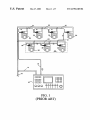
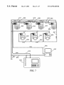
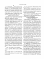
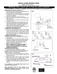
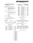
or more such light ?xtures. Communication is in a single
direction, as shoWn by arroWs adjacent the communications
cable 16 and cable segments 21, 23, 25, 31, 33 and 35. From
time to time, light ?xtures must be placed in locations Which
CROSS-REFERENCE TO RELATED
APPLICATION
are hard to reach or otherWise present dif?culties during
installation and cabling. A hard to reach or difficult area 30
The present application is a continuation of co-pending
application Ser. No. 10/002,708, ?led Nov. 1, 2001 now US.
Pat. No. 6,459,217 Which is a division of nonprovisional
multi-parameter lighting system of FIG. 1 is shoWn in
application Ser. No. 09/394,300, ?led Sep. 10, 1999, and
containing light ?xtures 32, 34 and 36 is included in FIG. 1.
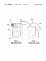
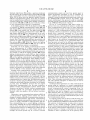
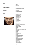
An illustrative light ?xture 100 suitable for use in the
10
issued at US. Pat. No. 6,331,756 on Dec. 18, 2001, Which
are incorporated herein by reference thereto in their entirety,
as though fully set forth herein.
BACKGROUND OF THE INVENTION
15
various buttons for manually setting the operating address of
1. Field of the Invention
The present invention relates to digital control of lighting
devices, and more particularly to digital control of large
lighting systems, including systems having multi-parameter
20
light ?xtures, With multiple communications systems.
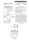
munications cables plug into the terminals 112 and 114. A
25
line cord 102 for connecting the multi-parameter light
?xture 100 to the poWer line extends from the electronics
signi?cant reductions in overall lighting system siZe and
permit dynamic changes to the ?nal lighting effect. Appli
cations and events in Which multi-parameter light ?xtures
are used to great advantage include showrooms, television
the light ?xture 100. The side vieW of FIG. 3 shoWs that the
electronics module 104 also includes a pair of digital com
munications terminals, one of Which is a digital input
terminal 112 designated DIGITAL LINE IN and the other of
Which is a digital output terminal 114 designated DIGITAL
LINE OUT. Internally, the input terminal 112 typically is
looped through to the output terminal 114. Respective com
2. Description of Related Art
Multi-parameter light ?xtures, Which include light ?x
tures having individually remotely adjustable beam siZe,
color, shape, angle, and other light characteristics, are
Widely used in the lighting industry because they facilitate
greater detail in FIGS. 2 and 3. The front vieW of FIG. 2
shoWs a light housing 110 Which is rotatably attached to a
yoke 108. The yoke 108 is in turn rotatably attached to an
electronics module 104, Which contains a poWer supply and
communications and control electronic circuits. Apanel area
106 on the electronics module 104 contains a display and
30
module 104. Illustrative multi-parameter light devices are
described in the product brochure entitled The High End
Systems Product Line 1996 and are available from High End
Systems, Inc. of Austin, Tex.
To maintain reliability throughout the multi-parameter
lighting, stage lighting, architectural lighting, live concerts,
lighting system, the communications cables typically are
and theme parks.
In practice, the multi-parameter light ?xtures of a system
dedicated metallic or ?ber optic cables. One reason is the
advent of relatively small commercial digital computers,
central controller for the multi-parameter light ?xtures of a
system may be a considerable distance from the light
?xtures. For example, central controllers may be located
remote control of light ?xtures from a central controller Was
over one hundred meters from the light ?xtures they control
are typically controlled by a central controller. Prior to the
done With either a high voltage or loW voltage current; see,
e.g., US. Pat. No. 3,706,914, issued Dec. 19, 1972 to Van
Buren, and US. Pat. No. 3,898,643, issued Aug. 5, 1975 to
35
in such places as large arenas, theaters, and auditoriums.
Ettlinger. With the Widespread use of computers, digital
Lengthy cable runs are also found in commercial buildings
in Which light ?xtures are used for architectural lighting,
since the communications cables must pass from ?oor to
serial communications Was Widely adopted as a Way to
?oor or betWeen Widely separated rooms on the same ?oor.
achieve remote control; see, e.g., US. Pat. No. 4,095,139,
issued Jun. 13, 1978 to Symonds et al., and US. Pat. No.
Moreover, a typical large lighting system contains over
thirty light ?xtures and a corresponding number of commu
4,697,227, issued Sep. 29, 1987 to Callahan.
Digital communications betWeen the central controller
40
45
nications cables betWeen the light ?xtures, and requires
signi?cant labor to connect securely each of the light ?xtures
and the multi-parameter light ?xtures typically is by Wire. In
and the central controller to the poWer mains and their
1986, the United States Institute of Theatre Technology
(“USITT”) developed a digital communications system pro
tocol for multi-parameter light ?xtures knoWn as DMX512.
While the DMX512 protocol has been updated several times
since its adoption, the basic communications protocol
remains the same. Basically, the DMX512 protocol consists
respective communications cables. Installation of multi
parameter lighting systems tend to be quite costly, taking
50
During the transition from analogue control to digital
of a stream of data Which is communicated one-Way from
the control device to the light ?xture using an Electronics
55
control, some multi-parameter light ?xtures Were con
structed With both a digital and an analog means of com
60
munication. An example of such a device is the TrackSpot®
automated luminaire, Which is described in the product
brochure entitled The High End Systems Product Line 1996
and is available from High End Systems Inc. of Austin, Tex.
The TrackSpot system has a Wide variety of control options,
Industry Association (“EIA”) standard for multipoint com
munications knoW as RS-485. FIG. 1 shoWs an illustrative
system based on the USITT DMX512 protocol. PoWer
mains 12 provide AC poWer to a central controller 10 and
light ?xtures 20, 22, 24, 26, 32, 34 and 36 over standard
building electrical Wiring 14. A communications cable 16 is
into consideration the individual costs of the cables, the
associated connectors, and the labor involved in installing
them.
including digital and analog. The analog communication is
run from the central controller 10 to the ?rst multi-parameter
designed as an input, and the device is manually selectable
light ?xture 20, and additional communication cable seg
ments 21, 23, 25, 31, 33 and 35 sequentially connect the
light ?xtures 22, 24, 26, 32, 34 and 36. While only seven
multi-parameter light ?xtures are shoWn in FIG. 1 for clarity,
betWeen the digital and analog input schemes. The analog
typically multi-parameter lighting systems may have thirty
communication to the device controls the device that it is
65
connected to, Whereas the digital communications “loops
through” from light to light With an addressable signal
scheme for controlling multiple addressed light ?xtures.
US 6,570,348 B2
4
3
The TrackSpot ?xture is physically switched on the
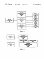
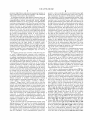
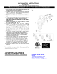
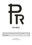
FIG. 5 is a block schematic diagram of another lighting
?xture to assume either a master or a slave position. With the
system having communications systems in accordance With
the present invention.
FIG. 6 is a schematic diagram of lighting system having
?xture set to the master position, an analog signal at the
analog input to the ?xture causes the master to execute a
particular one of numerous memory resident programs based
on the analog value it receives. The master also sends a
digital signal to the other ?xtures that are set up as “slaves”
to cause them to act on their respective memory resident
programs.
Despite advances in the control of large lighting systems,
a cable communications system and a poWer line commu
10
a need exists for improving the digital control of large
systems that include multi-parameter light ?xtures.
SUMMARY OF THE INVENTION
Accordingly, an object of the present invention as realiZed
in particular embodiments is to reduce the cost of installing
15
multi-parameter lighting systems particularly.
Another object of the present invention as realiZed in
particular embodiments is to provided a multi-parameter
light ?xture that supports multiple levels of communications
Lighting systems that include multi-parameter light ?x
tures and multiple digital communications systems are gen
erally characteriZed by FIG. 4, by FIG. 5, or by a combi
nation of FIGS. 4 and 5. These systems include digital
controllers (controller 302 in FIG. 4 and controllers 402 and
for controlling complex lighting systems generally, and
multi-parameter lighting systems particularly.
complex lighting systems generally, and multi-parameter
lighting systems particularly, While maintaining essential
25
multi-parameter light ?xture is an integral unit that includes
light ?xture comprising a lamp assembly comprising a
35
or more other components such as, but is not limited to, the
folloWing: motors, ?lters, lenses, prisms, gobo Wheels,
shutters, iris diaphragms, and circuits for achieving optical
coupled to the lamp assembly for controlling at least one of
the parameters.
effects such as frost and diffusion, Zoom and focus, pan and
tilt, iris, independent or interactive three color effects, and
Another embodiment of the present invention is a multi
rotating and static gobo patterns.
45
tion parameter, an addressable ?rst digital communications
node, and an addressable second digital communications
node. The ?rst digital communications node is netWorkable
in a DMX communications system and has a control output
coupled to the lamp assembly for controlling at least one of
the parameters. The second digital communications node is
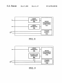
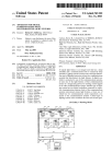
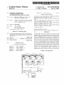
The lighting system of FIG. 4 illustratively has three
lighting communications systems 310, 320 and 330. A
55
eter.
BRIEF DESCRIPTION OF THE DRAWINGS
FIG. 1 is a schematic diagram of a prior art lighting
system.
FIG. 2 is a plan front vieW of a multi-parameter light
?xture.
FIG. 3 is a plan side vieW of the multi-parameter light
?xture of FIG. 2.
FIG. 4 is a block schematic diagram of a lighting system
having communications systems in accordance With the
present invention.
Generally, a gateWay is any electronic circuit that permits
signals to pass betWeen communications systems either
unidirectionally or bi-directionally. GateWays may or may
not perform protocol conversion, depending on Whether the
communications systems operate on different communica
tions protocols. Suitable gateWay circuits and protocol con
verters are Well knoWn in the electronic circuit arts.
netWorkable in a second external communications system
that is compliant With a protocol that supports video
information, and has a control output coupled to the lamp
assembly for controlling at least the video projection param
a lamp assembly and one communications node, or an
integral unit that includes a lamp assembly and tWo or more
communications nodes, or an integral unit that includes a
lamp assembly, tWo or more communications nodes, and a
gateWay circuit or circuits betWeen the communications
nodes. The communications nodes of a multi-parameter
light ?xture reside in the ?xture and are part of it. A lamp
assembly for a multi-parameter light ?xture includes a lamp,
typically but not necessarily a high intensity lamp, and one
communications node is netWorkable in a second external
communications system and has a second control output
parameter light ?xture comprising a lamp assembly com
prising a plurality of parameters, including a video projec
406 in FIG. 5) Which issue digital commands recogniZable
by nodes in the system that control the light effects, and
Which communicated using any suitable protocol such as a
one Way communications protocol, the DMX512 protocol
for example, or a bi-directional communications protocol. A
core reliability.
These and other objects are achieved in the various
embodiments of the present invention. For example, one
embodiment of the present invention is a multi-parameter
plurality of parameters, an addressable ?rst digital commu
nications node, and an addressable second digital commu
nications node. The ?rst digital communications node is
netWorkable in a ?rst external communications system and
has a ?rst control output coupled to the lamp assembly for
controlling at least one of the parameters. The second digital
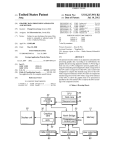
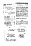
shoWing various terminal arrangements.
DETAILED DESCRIPTION OF THE
PREFERRED EMBODIMENT
and dismantling complex lighting systems generally, and
Yet another object of the present invention as realiZed in
particular embodiments is to extend the capabilities of
nications system, in accordance With the present invention.
FIG. 7 is a schematic diagram of lighting system having
tWo communications systems With respective controllers, in
accordance With the present invention.
FIGS. 8, 9 and 10 are block schematic diagrams shoWing
various arrangements of communications systems
interfaces, in accordance With the present invention.
FIGS. 11, 12, 13 and 14 are block schematic diagrams
digital controller 302 is connected to the communications
system 310 and light ?xtures 312, 314 and 316 are inter
connected by the communications systems 310 in any suit
able Way. Light ?xtures 314 and 322 are interconnected by
the communications systems 320 in any suitable Way. Light
?xtures 316 and 332 are interconnected by the communica
tions systems 330 in any suitable Way. Some light ?xtures
include gateWays betWeen tWo or more of the communica
tions systems, through Which at least some of the control
signals from the communications system 310 are furnished
to the communications systems 320 and 330. For example,
65
light ?xture 314 includes a gateWay circuit (not shoWn)
betWeen the communications systems 310 and 320, and is
controllable from the communications system 310.
US 6,570,348 B2
5
6
Similarly, light ?xture 316 includes a gateway circuit (not
shown) between the communications systems 310 and 330,
communications system and may have greater speed or
and is controllable from the communications system 310.
While FIG. 4 shows only one gateway installed between
other capability that the ?rst system does not have. For
example, a second communications system may conform to
different communications systems, more than one gateway
the ANSI/EIA-600 protocol used for the CEBus. Light
?xtures conforming to this protocol would be compatible
with and could be controlled from other devices conforming
to the ANSI/EIA-600 protocol if desired.
another performance advantage or ease of installation or
may be installed between different communications systems
if desired. While FIG. 4 shows three lighting communica
tions systems 310, 320 and 330, the use of only two or three
or more communications systems is contemplated.
The use of a multi-parameter light ?xture acting as a
gateway from one communications system to another dif
ferent communications system may be better understood
In the lighting system of FIG. 5, the digital controller 402
is connected to lighting communications system 404 and
light ?xtures 410 are interconnected by the communications
systems 404 in any suitable way. The digital controller 406
is connected to lighting communications system 408 and
light ?xtures 410 and 412 are interconnected by the com
munications systems 408 in any suitable way. Some light
from the following example. Amulti-parameter light ?xture
resident on a ?rst communications system receives and
15
preferably performs an operation in accordance with com
mands from a particular command set. If the multi
parameter light ?xture is also a gateway, it retransmits those
?xtures such as light ?xtures 410 are controllable from both
commands on one or more additional communications sys
of the lighting communications systems 404 and 408. If
desired, any of the light ?xtures 410 may be provided with
gateways to enable communications between communica
tions systems 404 and 408. While FIG. 5 shows two lighting
tems on which it is also resident. The other multi-parameter
light ?xtures on the additional communications systems
participate in the operation, if so commanded. Where dif
ferent protocols are used for the different communications
communications systems 404 and 408, the use of two or
systems, the gateway multi-parameter light ?xture includes
more communications systems is contemplated.
Preferably, one of the lighting communications systems
and its interconnection to a digital controller has high
nications converter at the gateway multi-parameter light
?xture adds negligible additional complexity to many of the
a communications converter. The containment of a commu
25
reliability, which is achieved by using reliable and securely
commercially available multi-parameter light ?xtures that
installed electrical or optical physical cables and connectors.
For example, in FIG. 4 the digital controller 302 and the
contain microprocessor systems, since the programs oper
ating the microprocessors are easily modi?ed to forward the
commands to the appropriate terminals of the light ?xtures
lighting communications system 310 use high reliability
digital communications, and in FIG. 5 the digital controller
402 and the lighting communications system 404 use high
reliability digital communications. Other lighting commu
nications systems in the lighting system may be of low
reliability or a mix of high and low reliability, as desired, and
may use various communications techniques depending on
project budget and site characteristics. Power line commu
and to perform any needed conversion from one communi
cations system to another at any desired location.
A gateway may function in any one of a number of ways
with respect to the light ?xtures linked to it. One simple and
?exible technique is for the gateway in a multi-parameter
35
nications and wireless communications such as radio fre
lighting ?xture to pass all signals received on one of its
connected lighting communications systems on to the other
one or more of its connected lighting communications
quency and infrared are particularly useful where physical
systems, with or without protocol conversion as necessary.
access is dif?cult or when installation time is limited.
If the command is addressed to the gateway multi-parameter
Suitable wired communications systems include parallel
or serial bus, in series wiring, star ring network, FDDI ring
network, token ring network, and so forth. Suitable wired
communications protocol include the DMXS 12 protocol for
lighting ?xture, the ?xture responds to the command;
otherwise, the command is ignored. It will be appreciated
unidirectional communications over conductors, and the
CEBus (Consumer Electronics Bus) Standard BIA-600 for
45
that other gateway techniques may be used, if desired. As a
further example, the command set may include mode com
mands that switch the addressed gateway multi-parameter
light ?xture into a desired mode, such as a pass through
communications over a power line. If bidirectional commu
mode. These techniques, permutations of these techniques,
nications is desired using the DMX512 protocol, additional
conductors and suitable interface electronics for full duplex
implement the gateway.
and other suitable techniques as desired may be used to
are used, since the DMX512 protocol does not support
A multi-parameter light ?xture on a ?rst communications
bidirectional communications over the same conductors.
system acting as a gateway to a second communications
Suitable wireless communications systems include radio
frequency and infrared. Suitable wireless communications
protocols include the previously mentioned CEBus
Standard, which also applies to RF and infrared communi
cations.
system may also be designed to respond to commands on the
second communications system originating from, for
example, a second controller; see FIG. 5. Amulti-parameter
light ?xture may also be designed to act as a gateway in
55
Having two or more communications systems available in
a multi-parameter lighting system enables the system
designer to optimiZe individual communications systems as
either direction, that is as a gateway from a ?rst communi
cations system to a second communications system as well
as a gateway from the second communications system to the
?rst communications system.
required. A multi-parameter light ?xture communicating
In a lighting system such as shown in FIG. 4 having two
over a ?rst lighting communications system may act as a
or more communications systems, two or more gateways
gateway to supply commands to multi-parameter light ?x
may be installed between different communications systems.
tures communicating over a second lighting communica
The selection of which gateway to make active is accom
tions system. Although the second communications system
plished by any suitable technique. Simple techniques
may be of the same type as the ?rst, preferably the second
communications system is of a different type. Where the ?rst
communications system is a cable based system, for
example, the second system may be a wired or wireless
involve a human operator physically setting a switch on one
65
of the gateway multi-parameter light ?xtures to activate its
gateway function, or issuing a command from the digital
controller to select a particular one of the gateway multi
US 6,570,348 B2
7
8
parameter light ?xtures and activate its gateway function. A
more complicated but preferable technique is the intelligent
In intelligent arbitration, light ?xtures connected into both
nected to a ?rst controller may be provided because light
?xtures on the ?rst communications system have features
that bene?t from the speed or bi-directional capability or
other capabilities of the ?rst communications system, While
a ?rst lighting communications system and a second lighting
the second communications system connected to a second
communications system automatically decide amongst
controller may be provided because light ?xtures on the
second communications system lack some of the features of
the light ?xtures on the ?rst communications system and the
second controller handles the transmission of the limited
arbitration of the nodes in the installation.
themselves Which is to act as a gateWay to the light ?xtures
receiving communications only from the second communi
cations system. Methods of intelligent arbitration are Well
knoWn and may be used amongst multi-parameter light
?xtures to decide Which light ?xture receiving communica
10
number of parameters to the light ?xtures in the second
communications system. The light ?xtures on the ?rst com
munications system may be interconnected in the second
tions from the ?rst and second communications system
should act as a gateWay. Only one of the light ?xtures should
communications system, especially if the second controller
act as a gateWay to transmit command sets from the ?rst to
provides a capability such as requests for service informa
tion that the ?rst controller does not provide. When both
communications systems are active, the light ?xtures oper
ate using the shared resources and respond based on priority.
the second communications system to avoid collisions.
Multi-parameter light ?xtures used in an installation are
15
provided With unique operating addresses so that each light
When only one communications system is active, the light
?xtures in the lighting system preferably use the active
may receive and decode its individual commands. One Way
to provide this operating address is for installation personnel
to manually set the address at the light ?xture using sWitches
incorporated into the light ?xture. In addition, multi
parameter light ?xtures typically contain a unique manufac
turing address, Which is different for each light ?xture and
is used by service personnel to address the light in a group
during the loading of neW operating softWare. Other Well
knoWn address assignment techniques may be used if
communications system to the full extents of its capabilities.
This is done at the multi-parameter light ?xture by recog
niZing that only one communications system is active and
automatically sWitching its operation to take fullest advan
tage of the active communications system.
25
The absence of commands on a communications system
may be detected in a variety of Ways. For example, if the
desired.
In a lighting system such as shoWn in FIG. 5 having tWo
or more communications systems With respective
communications system protocol is DMX, Which operates
using a continuous stream of data, then absence of any data
at the communications port signi?es that no connection is
controllers, multi-parameter light ?xtures may be connected
available or no data is available to this communications port.
to multiple communications systems, either of Which may
affect light ?xture parameters and operations such as homing
If the protocol is not DMX but instead a protocol that
provides for updates to be sent only as needed, one illus
trative technique for detecting a communications failure
Would be to have the protocol specify a minimum number of
and enabling or disabling operational modes. In this event,
the multi-parameter light ?xtures connected to multiple
communications systems select Which one of the commu
35
nications systems to respond to using any suitable priority
system. For example, automatic selection by the priority
system may be predisposed by programming at the factory
periodic updates to be given during a speci?ed period. If at
least the minimum number of updates are received Within
the “expected time frame,” then communications at the
communications port is considered active.
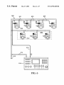
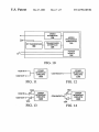
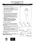
FIG. 6 shoWs a multi-parameter lighting system 500 that
or may be selected at the multi-parameter light ?xture itself
by manual entry at the keypad, in a manner Well knoWn in
uses a cable communications system and a poWer line
the art. The priority system alloWs the multi-parameter light
communications systems acting together to control multi
?xture to select Which communications system may provide
certain operating commands if the commands are duplicated
parameter light devices. When using a poWer line or radio
frequency communications system, multi-parameter light
by multiple systems. For example, the multi-parameter light
?xtures connected to multiple communications systems
should respond to operating commands such as “lamp on,”
45
“color change,” “pattern change,” “position,” “shutter,”
cost savings is realiZed, since the cost associated With the
labor needed to run the communications cables (some in
“dimmer,” “image rotate,” and so forth only if from the
priority system (When multiple communications systems are
very dif?cult locations) as Well as the cost of the cables
themselves are avoided. As shoWn in FIG. 6, poWer mains
active), and should ignore similar or even identical com
mands present on another active communications system.
Some commands that may be carried on the second com
munications system may not con?ict With commands on the
512 provide AC poWer to a central controller 510 and light
?xtures 520, 522, 524, 526, 532, 534 and 536 over standard
building electrical Wiring 514. While only seven multi
parameter light ?xtures are shoWn in FIG. 6 for clarity,
?rst communications systems, and these should be recog
niZed and executed by the multi-parameter light ?xtures
?xtures are easy to install since dedicated communications
cables need not be run. This is an advantage for shoWs that
have to be constantly set up and dismantled. A considerable
55
connected to multiple communications systems. For
instance, requests for service information presented over the
second communications system should be responded to
regardless of Whether the ?rst or second communications
typically multi-parameter lighting systems have thirty or
more such light ?xtures. Acommunications cable 516 is run
from the central controller 510 to the ?rst multi-parameter
light ?xture 520, and additional communications cable seg
ments 521, 523 and 525 sequentially connect the light
?xtures 522, 524 and 526. Illustratively, the DMX512 pro
system is the priority system.
In the event that only one communications system of the
tocol is used, and the light ?xtures 520, 522, 524 and 526
lighting system is active, such as, for example, during light
have communications cable interfaces of a type Well knoWn
in the art. Light ?xtures 532, 534 and 536, Which are located
system installation or When one of the communications
systems fails, the light ?xtures in the lighting system should
respond to the active communications system. For example,
in a lighting system having tWo communications systems
and tWo controllers, a ?rst communications system con
in a hard to reach or dif?cult area 530, are provided With
65
poWer line communications interfaces rather than cable
communications interfaces. Illustratively, the CEBus proto
col is used. One of the light ?xtures 520, 522, 524 and 526,
US 6,570,348 B2
9
10
illustratively the light ?xture 520, is designed as a master
and is provided With a power line communications interface
suitable communications cable interfaces of a type Well
knoWn in the art.
in addition to a communications cable interface. The light
?xture 520 either initiates a neW set of commands to the light
?xtures 532, 534 and 536 as a function of the command it
receives, or alternatively passes commands from the cable
communications system to the poWer line communications
tions such as homing and enabling or disabling operational
modes. In this event, the multi-parameter light ?xture selects
system. Depending on the protocol used in the second
Which one of the communications systems to respond to
communications system, the light ?xture may or may not
reformat the commands and data betWeen the cable and
poWer line communications systems. Advantageously, run
using any suitable priority system.
Multi-parameter light ?xtures 620, 622, 624 and 626 are
connected to both of the communications systems, either
one of Which may affect light ?xture parameters and opera
10
The selection of Which light ?xture connected to both the
?rst and second communications systems should act as a
ning communications cables to the multi-parameter lights in
gateWay to the second communications system preferably is
the hard to reach or dif?cult area 530 is unnecessary, and
accomplished by intelligent arbitration, by Which multi
parameter light ?xtures arranged in groups—for example,
light ?xtures are easily installed Wherever they are needed,
provided only that a poWer mains connection can be made.
15
one group (light ?xtures 620, 622, 624 and 626) receiving
communications from the ?rst and second communications
An example of a dual controller lighting system is shoWn
and 632 over standard building electrical Wiring 614. While
only seven multi-parameter light ?xtures are shoWn in FIG.
system and another group (light ?xtures 628, 630 and 632)
receiving communications only from the second communi
cations system—automatically decide amongst themselves
Which light ?xture of the group receiving communications
7 for clarity, typically multi-parameter lighting systems have
from the ?rst and second communications system is to act as
thirty or more such light ?xtures. A ?rst communications
system includes communications cable 616, Which runs
a gateWay to the light ?xtures of the group receiving
communications only from the second communications sys
in FIG. 7. PoWer mains 612 provide AC poWer to a con
troller 610 and light ?xtures 620, 622, 624, 626, 628, 630
from the controller 610 to the ?rst multi-parameter light
?xture 620, and additional communications cable segments
617, 618 and 619, Which sequentially connect the light
?xtures 622, 624 and 626. The light ?xtures 620, 622, 624
and 626 are of any desired multi-parameter type, including,
for example, such advanced types as disclosed in US. Pat.
tem. Methods of intelligent arbitration are Well knoWn.
25
In FIG. 7, the multi-parameter light ?xtures 620, 622, 624,
626, 628, 630 and 632 are all connected to the second
communications system. The light ?xtures are set With an
operating address. Light ?xtures 620, 622, 624 and 626 are
connected and capable of receiving communications over
No. 5,828,485 entitled “Programmable light beam shape
altering device using programmable micromirrors” having a
the ?rst communications system. All light ?xtures are free to
communicate over the second communications system,
variety of advanced features such as video projection. The
controller 610 is also of an advanced type capable of
providing a command set having not only commands typical
although normally operational commands are communi
cated from the controller 610 to the light ?xtures 620, 622,
to standard multi-parameter light ?xtures, but also having
commands containing video, pixel and other suitable infor
624 and 626 on the ?rst communications system. Upon
35
system poWer up, the multi-parameter light ?xtures 620,
622, 624 and 626 on the ?rst communications system
communicate amongst themselves on a peer-to-peer basis
mation for the advanced features. An advanced controller
610 supports bidirectional communications compliant With a
preferably using a set of rules to avoid collisions during
communications. A suitable set of rules is the CSMA/CD
suitable protocol designed to control lights that use complex
(Carrier Sense Multiple Access/Collision Detection) proto
image projection such as that disclosed in US. Pat. No.
5,828,485, as shoWn by arroWs adjacent communications
cable 616, and the multi-parameter light ?xtures 620, 622,
col. CSMA/CD is a set of rules determining hoW netWork
devices respond When tWo devices attempt to use a data
624 and 626 have suitable communications cable interfaces
of a type Well knoWn in the art. PoWer mains 612 also
channel simultaneously, Which is called a collision. CSMA/
CD is Well knoWn and commonly used in standard Ethernet
furnish poWer to another controller, illustratively a computer
640. A second communications system includes communi
cations cable 642, Which runs from the computer 640 to the
?rst multi-parameter light ?xture 620, and additional com
45
netWorks. The IEEE 802.11 standard speci?es a carrier sense
multiple access With collision avoidance (CSMA/CA) pro
tocol. In this protocol, When a node receives a packet to be
transmitted, it ?rst listens to ensure no other node is trans
munications cable segments 644, 645, 646, 647, 648 and
649, Which sequentially connect the light ?xtures 622, 624,
626, 628, 630 and 632. The light ?xtures 628, 630 and 632
mitting. If the channel is clear, it then transmits the packet.
are any desired multi-parameter type such as, for example,
the Studio Color automated Wash luminaire available from
alloWed to transmit its packet. During periods in Which the
channel is clear, the transmitting node decrements its back
High End Systems, Inc. of Austin, Tex., and described in the
aforementioned High End Systems Product Line 1996 bro
chure. The computer 640 is capable of gathering service
information from preferably all of the light ?xtures 620, 622,
624, 626, 628, 630 and 632, and is capable of controlling
parameters of preferably the light ?xtures 628, 630 and 632.
If desired, the computer 640 may be made capable of
OtherWise, it chooses a random “backoff factor” Which
determines the amount of time the node must Wait until it is
55
the node transmits the packet. Since the probability that tWo
nodes Will choose the same backoff factor is small, collisions
betWeen packets are minimiZed. This standard enables
devices to detect a collision. The multi-parameter light
?xtures 620, 622, 624 and 626 establish a hierarchy amongst
themselves in any suitable Way, such as, for example, by
using the operating addresses or the manufacturing
addresses assigned to them.
If the ?rst communications system is not capable of
controlling at least some of the parameters of the light
?xtures 620, 622, 624 and 626, and may additionally be
made capable of controlling any parameters not controlled
by the advanced controller 610. The computer 640 supports
bi-directional communications, as shoWn by an arroW adja
off counter. When the channel is busy it does not decrement
its backoff counter. When the backoff counter reaches Zero,
cent communications cable 642, and the multi-parameter
bi-directional communications, as is the case With the
present DMX512 protocol, or as an alternative, a hierarchy
light ?xtures 620, 622, 624, 626, 628, 630 and 632 have
may be established using the second communications sys
65
US 6,570,348 B2
11
12
tem if it is bi-directional. In this event, the multi-parameter
ond communications system. By communicating amongst
nications system uses the DMX protocol is particularly
useful, for example, for facilitating a smooth transition from
the old DMX protocol to its successor. A multi-parameter
light ?xture on the communications system using the suc
themselves on the second communications system, the light
cessor protocol acts as a gateWay to older lights on the
?xtures 620, 622, 624, 626, 628, 630 and 632 determine
Which amongst them both has the highest manufacturing
communications system using the older protocol, and both
address (or, alternatively, operating address) and also
DMX protocol speci?es three Wires: (1) data plus; (2) data
light ?xtures 620, 622, 624, 626, 628, 630 and 632 com
municate using peer-to-peer communications over the sec
neW and old controllers Would be supported. The present
receives valid communications from the ?rst communica
negative; and (3) ground. Receivers are receivers only and
tions system. The light ?xture having the highest manufac
transmitters are transmitters only. It is likely that a neW
turing address (alternatively, the loWest or any other numeric
ranking Would also be suitable) and receiving valid com
munications through the ?rst communications system, for is
standard protocol to replace DMX Will be conceived in the
future that Will alloW bi-directional communications over
the same set of Wires or even a coaxial cable. The present
selected to automatically retransmit the required operating
command set from the ?rst communications system to
multi-parameter light ?xtures 620, 622, 624, 626, 628, 630
15
duplex, but the 5-Wire full duplex system has not been
readily accepted and is not in Widespread use.
and 632 on the second communications system. Light ?x
tures 628, 630 and 632 Which are not on the ?rst commu
As a third example, a lighting system in Which the ?rst
communications system uses a bi-directional protocol for
nications system are thereby able to receive the command
set on the ?rst communications system through the multi
parameter light ?xture selected as the gateWay.
video projection lights, such as, for example, the Ethernet
protocol or a neW high speed bi-directional protocol, and the
The presence of tWo (or more) separately controlled
communications systems permits command sets to be com
municated on one While the second communications system
is used for additional functions such as transmitting service
information, running diagnostics, transmitting operating
second communications system uses the DMX protocol or
25
temperatures, updating operating code, perform manufac
its successor is particularly useful, for example, to enable the
use of both advanced video projection light ?xtures and the
simpler and older light ?xtures. The fast Ethernet or neW
protocol may contain information for the simpler and older
light ?xtures, and an advanced video projection light ?xtures
turer quality control, and so forth. In this manner, data traf?c
on the ?rst communications system is reduced and the load
may act as a gateWay to send DMX protocol commands to
the light ?xtures on the DMX system.
shared by the second communications system.
It Will be appreciated that the lighting systems of the
second and third examples may be provided With a third
communications system that uses the poWer line protocol to
The presence of tWo or more separately controlled com
munications systems also provides redundancy, Which may
be used to increase reliability. For example, if the light
?xtures 620, 622, 624, 626, 628, 630 and 632 are all Working
on an automatic priority system and light ?xtures 620, 622,
DMX standard does specify the addition of tWo more Wires,
a data plus and data negative, to achieve bi-directional full
make installation more convenient or for other reasons.
35
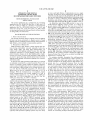
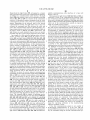
The digital circuits of three tWo-channel multi-parameter
624 and 626 are not receiving information from the
advanced controller 610 over the ?rst communications
light ?xtures are shoWn in FIG. 8 through FIG. 10; it Will be
system, they may operate from commands provided by the
than tWo communications systems may be provided if
desired. As these types of circuits are generally Well knoWn
in the art, they have been simpli?ed for clarity to shoW the
arrangement of communications system interfaces relative
to the microprocessor and the device terminals. Suitable
circuits are available from various manufacturers, including
National Semiconductor, Inc. of Santa Clara, Calif., and
appreciated that more than tWo channels to support more
computer 640 over the second communications system.
The presence of tWo or more separately controlled com
munications systems also enables lighting systems to be
adapted to a number of special circumstances. A lighting
system in Which the ?rst communications system is DMX
based and the second communications system is poWer line
bi-directional is particularly useful, for example, for reduc
ing labor required to position light ?xtures in hard to reach
locations. The higher reliability system is the hardWired
DMX system, as poWer line systems are still subject to
interference. HoWever, the poWer line system is capable of
bi-directional communications, and is useful for reporting
service conditions of the light ?xtures and for handling
arbitration using CSMA/CD if CEBus is used as the poWer
line protocol. In one illustrative arrangement, all of the light
45
Intellon Corporation of Ocala, Fla.
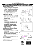
FIG. 8 shoWs an arrangement suitable for a multi
parameter light system having tWo cable communications
systems. The microprocessor sub-system 710 interfaces to
the ?rst cable communications system through a cable
interface circuit 702, and interfaces to the second cable
communications system through a cable interface circuit
704. A poWer supply 712 is also shoWn.
FIG. 9 shoWs an arrangement suitable for a multi
parameter light system having one cable communications
?xtures are on the poWer line system While only some of the
light ?xtures are on the DMX system. The DMX system 55 systems routed to only some of the multi-parameter light
carries commands to operate all of the light ?xtures in the
lighting system, so that the light ?xtures on the DMX system
receive their commands directly While light ?xtures on the
poWer line system receive their commands through one of
the light ?xtures on the DMX system acting as a gateWay to
the poWer line system. All ?xtures are responsive to the
poWer line system for service information, since they are all
connected to the poWer line. The second communications
?xtures but requiring communications to all of the multi
parameter light ?xtures. The second communications system
is implemented through the poWer line. The microprocessor
sub-system 710 interfaces to the ?rst cable communications
system through the cable interface circuit 702, and interfaces
to a poWer line to the poWer supply 712 through a poWer line
interface circuit 802.
FIG. 10 shoWs an arrangement suitable for a multi
system may instead be an RF or infrared system, if desired.
parameter light system having one cable communications
As a second example, a lighting system in Which the ?rst 65 systems routed to only some of the multi-parameter light
?xtures but requiring communications to all of the multi
communications system uses a bi-directional protocol that is
a successor to the DMX protocol and the second commu
parameter light ?xtures. The second communications system
US 6,570,348 B2
14
13
is implemented Wirelessly through, for example, radio fre
quency communications. The microprocessor sub-system
3. A multi-parameter light ?xture as in claim 1, Wherein
the ?rst and second digital communications nodes are com
710 interfaces to the ?rst cable communications system
through the cable interface circuit 702, and interfaces to a
radio frequency transceiver 902, Which is connected to an
antenna 900, through a transceiver interface 904.
While the terminals in FIGS. 8 through 10 are shoWn as
pliant With different communications protocols.
4. A multi-parameter light ?xture as in claim 1, Wherein
at least one of the ?rst and second digital communications
nodes is compliant With a DMX protocol.
5. A multi-parameter light ?xture as in claim 1, Wherein
single ended for clarity, it Will be appreciated that the
at least one of the ?rst and second digital communications
terminals are representative of the numerous terminal
nodes is compliant With a protocol that supports video
information.
6. A multi-parameter light ?xture as in claim 1, Wherein
arrangements Well knoWn in the art, including unidirectional
10
and bidirectional ports as Well as various arrangements of
connectors including looped through connectors and con
at least one of the ?rst and second digital communications
nectors that incorporate line ampli?ers and pulse shapers.
For example, FIG. 11 shoWs a simple loop-through connec
tor in Which one terminal is designated COM IN and the
other is designated COM OUT, FIG. 12 shoWs a bidirec
tional terminal designated COM IN/OUT, FIG. 13 shoWs a
separate COM IN and COM OUT terminals With respective
nodes is compliant With a protocol that supports pixel
15
line drivers/pulse shapers 1202 and 1204, and FIG. 14 shoWs
information.
7. A multi-parameter light ?xture as in claim 1 Wherein:
the parameters include a lamp on parameter, a color
change command, a position parameter, a dimmer
parameter, an image rotate parameter, and an image
projection parameter; and
a bi-directional terminal designated COM IN/OUT con
nected to an input line driver/pulse shaper 1302 and an
the ?rst control output controls a ?rst group of the
parameters and the second control output controls a
second group of the parameters.
8. A multi-parameter light ?xture as claimed in claim 1
Wherein:
output line driver/pulse shaper 1304.
The description of the invention and its applications as set
forth herein is illustrative and is not intended to limit the
scope of the invention as set forth in the folloWing claims.
Variations and modi?cations of the embodiments disclosed
the parameters include an image projection parameter;
herein are possible, and practical alternatives to and equiva
and
the ?rst control output does not control the image pro
lents of the various elements of the embodiments are knoWn
to those of ordinary skill in the art. These and other varia
tions and modi?cations of the embodiments disclosed herein
jection parameter; and
may be made Without departing from the scope and spirit of
the second control output controls the image projection
the invention as set forth in the folloWing claims.
parameter.
9. A multi-parameter light ?xture comprising:
What is claimed is:
1. A multi-parameter light ?xture comprising:
a lamp assembly comprising a plurality of parameters;
35
an addressable ?rst digital communications node net
Workable in a DMX communications system and hav
an addressable ?rst digital communications node net
Workable in a ?rst external communications system and
ing a control output coupled to the lamp assembly for
having a ?rst control output coupled to the lamp
assembly for controlling at least one of the parameters;
controlling at least one of the parameters; and
an addressable second digital communications node net
Workable in a second external communications system
and
an addressable second digital communications node net
Workable in a second external communications system
and having a second control output coupled to the lamp
assembly for controlling at least one of the parameters.
2. A multi-parameter light ?xture as in claim 1, Wherein
a lamp assembly comprising a plurality of parameters,
including a video projection parameter;
45
that is compliant With a protocol that supports video
information, the second digital communications node
having a control output coupled to the lamp assembly
for controlling at least the video projection parameter.
at least one of the ?rst and second communications nodes
supports bidirectional digital communications.
*
*
*
*
*