Download Selectable audio controlled parameters for multiparameter lights

Transcript
US006249091B1
(12) United States Patent
(10) Patent N0.:
(45) Date of Patent:
Belliveau
(54)
(76)
SELECTABLE AUDIO CONTROLLED
PARAMETERS FOR MULTIPARAMETER
LIGHTS
Inventor:
5,209,560
5/1993 Taylor et a1. ........................ .. 362/85
5,493,281
2/1996 Owens
5,896,457
4/1999
5,921,659
7/1999 Hunt et al.
Tyrrel
340/825.24
.......
. . . . . ..
381/56
. 362/233
OTHER PUBLICATIONS
“Trackspot User Manual”; ftp://ftp.highland.com/pub/Prod
Subject to any disclaimer, the term of this
patent is extended or adjusted under 35
ucts/Trackspot/manual/tsv1.pdf.
U.S.C. 154(b) by 0 days.
* cited by examiner
(21) Appl. No.: 09/566,763
May 8, 2000
(22) Filed:
(51) Int. Cl.7 ................................................... .. H05B 37/00
(52) US. Cl. ........................ .. 315/312; 315/316; 315/362;
(58)
Jun. 19, 2001
6,166,496 * 12/2000 Lys et al. ........................... .. 315/316
Richard S. Belliveau, 10643 Floral
Park, Austin, TX (US) 78759
Notice:
US 6,249,091 B1
Primary Examiner—Haissa Philogene
(74) Attorney, Agent, or Firm—Walter J. TencZa, Jr.
(57)
ABSTRACT
Individual variable parameters of a multiparameter lighting
362/85; 340/82524
device may be varied in response to a processed audio
Field of Search ................................... .. 315/149, 154,
signal. The multiparameter lighting device is equipped With
315/292, 295, 312, 316, 362; 362/85, 233,
239; 340/82522, 825.24
an audio transducer to receive sound Waves in the vicinity of
the device. The audio signal generated by the transducer in
response to the sound Waves is sent to a signal processor
References Cited
Where the audio signal is processed and converted to a
U.S. PATENT DOCUMENTS
parameter lighting device. The multiparameter lighting
(56)
control signal for varying selected parameters of the multi
3,635,121
1/1972
3,720,939 *
3/1973 Polanek et al.
Knauff ................................. .. 84/464
340/815.46
4,392,187 *
7/1983
Bornhorst ........ ..
4,394,656
7/1983
Goettsche .... ..
340/825.73
10/1983
Smith et al. ..
..... .. 367/197
4/1984
Hunter ........ ..
.. 84/464 R
4,408,308
4,440,059
4,621,557
4,753,148
5,023,517
*
11/1986
Newell
......
362/233
. . . ..
84/1.19
6/1988 Johnson
6/1991 Husak ..... ..
.... .. 84/464
315/200
5,083,064
1/1992 Jones, Sr. ..
315/294
5,140,304
8/1992
Miller ................................. .. 340/472
device is operated remotely from a control device using a
digital communication scheme. An operator of the control
device may remotely select Which parameter of the multi
parameter lighting device may be varied in response to the
processed audio signal. One or several parameters may be
varied in response to the processed audio signal. The inten
sity of the light source may also be varied in response to the
processed audio signal.
29 Claims, 5 Drawing Sheets
U.S. Patent
Jun. 19, 2001
Sheet 1 015
US 6,249,091 B1
U.S. Patent
Jun. 19, 2001
Sheet 2 015
Fig. 2A
(Prior Art)
/
Fig. 2B
(Prior Art)
10o
/
139
US 6,249,091 B1
140\
100
CE
136 138 \1 (131
102
13; \\g’;1 / 11\séf/zl/mo
if
11317, 52/9
133
114\
/
Q‘
I
*132
/1°4
\_,/
152//—\4 l
110
k,
//
116
113
\W
150
/
112
104
114
{0/
/ 120
110
U.S. Patent
Jun. 19, 2001
Sheet 3 015
US 6,249,091 B1
U.S. Patent
Jun. 19, 2001
Sheet 4 015
US 6,249,091 B1
Fig. 4
410
0
414
O
4|
|
/
420
416
\_
450
_\
418
U.S. Patent
Jun. 19, 2001
Sheet 5 015
US 6,249,091 B1
500
555
556
557
/
DIED
550
“
+0111 @
576
577
US 6,249,091 B1
1
2
SELECTABLE AUDIO CONTROLLED
PARAMETERS FOR MULTIPARAMETER
LIGHTS
additional operator inputs to specify each parameter of the
multiparameter lighting device).
For instance, to set the color parameter of a multiparam
eter light may require setting a color Wheel to a particular
rotational position (a color Wheel may typically have eight
FIELD OF THE INVENTION
The invention relates to stage lighting and more particu
larly multiparameter lights With remote controlled param
eters.
BACKGROUND OF THE INVENTION
10
Stage lighting instruments may be used in theatre, rock
concerts, restaurants, nightclubs, or special events. Multi
parameter stage lighting instruments or devices are typically
comprised of a light source and one or more parameters that
may be controlled by an operator through a control device.
US. Pat. No. 4,392,187 to Bohnhorst, Which is incorporated
scenes of selected colors are sequenced at the control device
15
from the control device. The prior art multiparameter light
20
tiparameter lighting devices may offer several variable
parameters such as pan, tilt, color, pattern, iris and focus.
Multiparameter lighting devices are often controlled by a
remote control device under the direction of an operator. The
remote control device is typically hardWired to the multi
grammed scenes (that he programmed) sequentially by
ing devices do not typically store the “scenes” or if they are
stored they are pre-stored as in the prior art TRACKSPOT
lighting system having automatically variable position,
color, intensity and beam divergence,” describes multipa
by the operator. The operator may “play back” the pro
inputting a command to the control device or by a signal
by reference and Which is titled: “Computer controlled
rameter lighting devices and a central control device. Mul
apertures one for each color) Which is located on the
multiparameter lighting device. The color Wheel of a mul
tiparameter lighting device may index from one color (one
rotational position) to another When a color change com
mand is received from the control device. If the operator
Wants to sequence several colors from the Wheel to be placed
in the light path he normally must program a separate scene
for each color to be presented into the light path. Next, the
(registered trademark) device at a factory. The TRACK
SPOT (registered trademark) device is disclosed in TRACK
SPOT (registered trademark) User Manual, copyright High
25
End Systems, Inc. 1997, P/N 60600034, Version 4.1 Which
is incorporated by reference. The control device, Which is
located remotely, sends control signals Which cause the
parameter lighting devices through communication lines and
scenes to sequence. The programming of the shoW, With its
corresponding scenes, can be very time consuming for the
there is “remote” control in the sense that the multiparameter
lighting devices may be at distant locations. An operator
may program the control device to produce a shoW With the
operator, as each multiparameter lighting device might be
individually addressed and its many parameters varied.
multiparameter lighting devices.
30
In order to reduce the programming time that the operator
requires to be creative, manufactures of multiparameter
The shoWs programmed by the operator may consist of
lighting devices have included various additional commands
tWenty or more multiparameter lighting devices. Each mul
tiparameter lighting device may have as many as eight to
tWelve parameters that may be varied to produce a desired
lighting effect. The parameters to be varied are selected by
an operator of the remote control device. The operator may
program the multiparameter lighting devices from the con
trol device to produce a “scene”. A scene is produced by
for many of the parameters. These various additional com
mands might be considered as macros. A color Wheel
varying the parameters for each of the multiparameter
lighting devices as to produce a desired effect. In the prior
art Within a scene a particular multiparameter lighting device
Will have its parameters set in a particular manner, for
example the color may be set to “red”, the tilt may be set to
ninety degrees, the pattern may be set to a circular pattern,
35
additional commands or macros may include random color
40
ing one of the color parameter macros, the operator can save
45
As another example, a mechanical shutter parameter used
to blackout the light emitted by the multiparameter lighting
device considerable time to program. For each scene the
50
55
particular multiparameter lighting device, and then after the
address signal has been sent, alloWs the operator through
device, may not only be programmable “on or off” but
different actions of the shutter may also be chosen. This
means for a stroboscopic effect Where the shutter may open
and close several hundred times, the operator need not
program the shutter to open and close several hundred times
by programming several hundred scenes that sequence.
Instead the operator may communicate from the control
device to the multiparameter lighting device a macro com
mand that operates from the operating memory of the
multiparameter lighting device. This macro command may
able time programming the shoW using the control device.
Sometimes the shoW rehearsal times do not alloW enough
parameter lighting device, it can be very time consuming for
the operator to address each one. (“Addressing” typically
requires an operator of the control device to identify by
operator inputs the“address” or unique identi?cation for a
that might be accomplished using multiple scenes With the
corresponding required indexing commands.
rameter lighting devices may take the operator of the control
time for the operator to be as creative as they Would like.
With so many parameters available from each multi
at a fast change speed, random color at a sloW change speed,
color spin at a fast change speed (the color Wheel rotates
continuously), color spin at a sloW change speed. By select
the programming time necessary to create something similar
Each scene for the total of the tWenty or more multipa
the shoW that utiliZes tWenty or more multiparameter light
ing devices may have ?fty to one hundred scenes Where each
scene contains hundreds of parameters of many multiparam
eter lighting devices that are varied.
The operator of the control device may spend consider
often respond to indexing commands that are sent to the light
from the control device. An indexing command alloWs the
operator to choose Which color is to be placed in the light
path of the multiparameter lighting device. The various
etc.
average of tWenty multiparameter lighting devices often
comprised of eight to tWelve parameters each, results in a
large amount of options for the operator. The ?nal result of
utiliZed by the multiparameter lighting device may most
provide the repetitive opening and closing of the shutter
60
necessary to create the stroboscopic effect.
The operator of the control system may implement several
macros in to each scene during the programming of the
shoW. Many multiparameter lighting devices may have
several macros available per parameter. The macro com
65
mands available affect the parameters of the multiparameter
lighting device, save the operator time and alloW for greater
creativity.
US 6,249,091 B1
3
4
After programming the show on the control device, the
shoW containing all the scenes and corresponding param
eters for each of the multiparameter lighting devices is
recalled from the control device’s memory. The scenes can
specify additional parameters. The parameters of the multi
parameter lighting device may be the color emitted by the
device, tilt of the device, a pattern of light emitted by the
device, or the intensity of the light emitted by the device.
be called up during the actual shoW by the operator Who may
be present at the control device during the shoW or they
provides the ?rst digital communications signal. The control
might be synchroniZed to a timer, so that they are automati
cally called up during the shoW. If the scenes are called up
rameter lighting device through one or more communication
In one embodiment a control device is provided Which
device may be electrically connected to the ?rst multipa
by the operator during the shoW, it is important that the
correct scene be called up at the correct moment during the
shoW. During a musical or a rock concert, the operator may
call up scenes precisely in time With a climactic musical
score. This offers the audience of the shoW a sense that the
lines.
10
may have a sound transducer for receiving sound Waves, a
lighting is tracking or responding to the shoW.
Various methods of controlling a shoW to audio Without
the operator precisely keeping time With a musical score
have been tried in the prior art. Control systems such as the
node for receiving a digital communications signal from the
15
devices to be modi?ed in response to a particular audio
electrical signal. The control device may provide various
digital communications signals to control the multiparam
ler as illustrated in the High End Systems All Product
Brochure have included an audio input to the control device.
An audio signal is provided to the audio input of the control
device. This audio input is converted to a control signal that
is used to advance a scene that has already been programmed
eter lighting devices. The communication signals may be
provided in response to operator inputs supplied at the
control device.
The present invention in various a embodiment provides
by an operator. Several scenes may be advanced as an audio
25
mean Where a control device is located at a different location
At least one manufacture has included a transducer or
Wired system is used. From time to time the Wires can not
be run and the hard Wired communications node at the
control device is plugged into a transmitter. In a Wireless
microphone Within the multiparameter lighting device hous
ing to detect an audio signal. The TRACKSPOT
(trademarked) multiparameter lighting device as illustrated
in the High End Systems All Product Brochure is equipped
35
unit”. The master unit converts the audio signal received by
the microphone and utiliZes the converted signal to advance
the preprogrammed scenes contained Within the master’s
form, a transmitter Would typically send the communica
tions signal or signals to a receiver that outputs again to hard
Wire. The present invention in one embodiment alloWs the
operator of a control device for a group of multiparameter
lighting devices the ability to select audio macros for certain
equipped parameters of the multiparameter lighting devices.
For eXample, a color parameter of a multiparameter lighting
device may respond to the prior art commands received from
memory. The master in turn advances the scenes of the rest
of the multiparameter lighting devices that are on the same
communication system visually simultaneously With the
audio advance signal received by the master. This prior art
audio advance system is limited as it only advances the
preprogrammed scenes to a processed audio signal. An
the ability to “remotely” select audio controlled parameters
for multiparameter lighting devices. “Remotely” is used to
from a multiparameter lighting device but the control device
may still be hardWired to the multiparameter lighting device
through communication lines. For the most part, the hard
the scenes.
With a microphone for advancing scenes When one of the
multiparameter lighting devices is selected as a “master
control device; and a processor for causing an individual
parameter of any of the plurality of multiparameter lighting
High End Systems INTELLABEAM (trademarked) control
signal is received at the input of the control device. Unfor
tunately this prior art method of advancing the scenes to
audio only advances the preprogrammed scenes and What
ever parameters have changed due to the programming of
Aplurality of further multiparameter lighting devices may
also be provided Whose parameters can be controlled by the
control device. Each further multiparameter lighting device
45
operator cannot program a scene at the control system and
select a parameter of an individual TRACKSPOT
operator inputs of a control device such as color indeX or
macros such as color spin or random color yet also respond
to certain audio controlled macros. The present invention in
one embodiment alloWs several parameters of a multipa
rameter light to be selected to respond to an audio signal
While several others may be selected not to respond to the
audio signal.
(trademarked) multiparameter light to be audio responsive.
The Trackspot system only advances the factory pro
With embodiments of the present invention, a much
greater dimension of control options are made available for
grammed scenes to the audio. When a scene is advanced the
parameters of the lights in that scene are not audio respon
multiparameter lighting devices. During the programming of
shoWs that have limited programming time available, the
audio controlled parameters alloW the operator of the control
s1ve.
SUMMARY OF THE INVENTION
55
device more creativity and as such greater productivity.
Embodiments of the present invention alloW an operator of
The present invention in one embodiment provides an
the multiparameter lighting devices to select, during
apparatus comprising a ?rst multiparameter lighting device,
programming, Which parameter of Which light is to be
responsive to audio signals.
The multiparameter lighting device of the invention can
Wherein the ?rst multiparameter lighting device is com
prised of a ?rst transducer, and a ?rst node for receiving a
?rst digital communications signal, and a ?rst processor.
be equipped With a sound transducer such as a microphone
for receiving external sound Waves and converting the sound
The ?rst transducer may change sound Waves into a ?rst
audio electrical signal. The ?rst processor may receive a
digital communications signal and in response cause a ?rst
Waves into one or more audio electrical signals. The audio
electrical signal derived from the microphone may be ampli
parameter of the ?rst multiparameter lighting device to be
modi?ed in response to the ?rst audio electrical signal. The
?rst digital communications signal may specify the ?rst
parameter. The ?rst digital communications signal may
?ed and the ampli?ed audio electrical signal may be fed to
65
an analog to digital converter as part of a signal processor.
The ampli?er and analog to digital converter, and other
signal processing, may be integrated into a microprocessor
US 6,249,091 B1
5
6
on the multiparameter lighting device. The microprocessor
line 54 (Which may be a communications bus comprised of
processes the digital audio signal in various Ways that are
tWo or more Wires) is connected to control device 50 and to
derived from operating softWare programmed in the micro
processor. For instance, the digital audio signal may be
processed to remove all frequency components eXcept the
is electrically connected to communications output 2b and to
the communications input 2c. Digital communication line 55
communications output 4c. Digital communication lines 56,
loW frequencies.
The microprocessor may process the audio signal to
remove all frequency components eXcept the midrange
audio frequencies. The processed midrange information may
be used by the microprocessor to effect changes to the
parameters of the multiparameter lighting device controlled
by the processor. The microprocessor may omit all fre
quency components eXcept the loW frequency components.
57, 58, 59, and 60 are electrically connected to communi
cations output 4b and communications input 6c, communi
cations output 6b and communications input 8b, communi
10
transmit control information from the control device 50 to
The loW frequency information might be processed by the
microprocessor to effect changes to the selected parameters
cations output 8c and communications input 14b,
communications output 14c and communications input 12b,
and communications output 12c and communications input
10b respectively. The digital communication lines 54—60
15
of the multiparameter lighting device controlled by the
microprocessor.
the multiparameter lighting devices 2—14, such as control
information for controlling all available parameters of each
of the multiparameter lighting devices 2—14 such as for
eXample, but not limited to pan, tilt, color, shutter, pattern
ming a scene. The creation of the scene may involve the
and focus.
FIG. 2A illustrates a prior art multiparameter lighting
programming of several multiparameter lighting devices and
their parameters. One of the multiparameter lighting devices
device 100. The multiparameter lighting device 100 includes
a base 102, a bearing 104, a yoke 114, bearings 116 and 118,
The operator of the control device may start by program
and lamp housing 120.
The lamp housing 120 is connected to the yoke 114 by
is addressed by the control device under the guidance of an
operator as it has been in the prior art. The operator may
select from the addressed multiparameter lighting device a
parameter to control. For instance, the operator may select to
bearings 116 and 118 Which are shoWn in simpli?ed form.
The yoke 104 is connected to the base 102 by bearings 104
shoWn in simpli?ed form.
The lamp housing 120 includes an aperture 112 for light
control the color parameter. With the multiparameter light
ing device of embodiments of the present invention, the
color command set for the color parameter of a particular
multiparameter lighting device might include one or several
audio macros that affect the color parameter. The control
device Would tell a multiparameter lighting device Which
to be emitted from the lamp housing 120. The lamp housing
120 houses various electronic, mechanical and optical parts.
The external parts shoWn in FIG. 2A are knoWn in the prior
art. The present invention Will introduce neW internal parts
audio macro is to be eXecuted in response to Which audio
signal inputs.
BRIEF DESCRIPTION OF THE INVENTION
35
or neW operation of internal parts such as Will be shoWn and
described With reference to FIG. 3C into the prior art
structure of FIG. 2A.
The base 102 typically houses electronic circuitry for
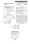
FIG. 1 illustrates a typical multiparameter light system of
the prior art;
controlling positioning of the lamp housing 120. The lamp
housing 120 may be “positioned” by remote control
(“positioning” means control of “tilt” and “panning”). “Tilt
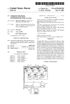
FIG. 2A illustrates the general appearance of a prior art
type of multiparameter lighting device;
ing” the lamp housing 120 refers to tilting the lamp housing
FIG. 2B illustrates a side vieW of the prior art multipa
rameter lighting device described in FIG. 2A;
FIG. 3A illustrates a color Wheel of the prior art. ShoWn
“panning” the lamp housing 120 refers to panning the yoke
114, and thus the lamp housing 120, about the bearings 104
FIG. 3A;
parameters. The base 102 includes a display and keypad
device 130. The display and keypad device 130 includes
120 about bearings 116 and 118 With respect to the yoke 114;
With respect to the base 102. The “positioning” of the lamp
are several color apertures, a motor and the color Wheel;
housing 120 can thus be controlled With at least these tWo
45
FIG. 3B is a side vieW of the color Wheel described in
FIG. 3C illustrates a multiparameter lighting device of an
buttons 131—134 and Light Emitting Diode Displays
embodiment of the present invention;
135—138. The buttons 131—134 are input devices to alloW on
FIG. 4 illustrates a multiparameter lighting device of an
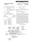
board control of the various parameters for such things as
embodiment of the present invention; and
FIG. 5 illustrates a multiparameter lighting system in
setting the address of a multiparameter lighting device (such
accordance With an embodiment of the present invention.
(such as pan, tilt, etc). The LED displays 135—138 (or a
lesser number of such LEDs) are shoWn in simpli?ed form
DETAILED DESCRIPTION OF THE DRAWINGS
as device 100) and for performing tests on the parameters
55
of the prior art. A control device 50 is shoWn that is used to
program the parameters of a plurality of multiparameter
lighting devices 2, 4, 6, 8, 10, 12, and 14. The control device
50 and the multiparameter lighting devices 2 through 14 are
connected to the poWer source 30 (Which may be an alter
nating current “AC” poWer source) through poWer lines 52a
and 52b. Although seven multiparameter lighting devices
2—14 are shoWn, typical systems may consist of tWenty or
more of such multiparameter lighting devices.
A digital communication line comprised of a plurality of
communication lines is illustrated. Digital communication
and are typically used to display the address information as
Well as service information for the multiparameter lighting
device 100. The base 102 includes input (152) and output
(150) communications connections (Which are shoWn in
FIG. 2B) for connecting to in and out electronic communi
cations lines.
The display and keypad device 130 is used to select a
FIG. 1 illustrates a typical multiparameter light system 10
65
communications address for the multi-parameter lighting
device 100. By using the display system and keypad 130 the
multi-parameter lighting device 100 (and any similar multi
parameter lighting device) may be given a unique address so
that the multiparameter lighting device 100 may respond
separately to commands from a control device (not shoWn
US 6,249,091 B1
7
8
but may be control device 50 as in FIG. 1) over a commu
shaft 361 Which is connected to the motor 362. Optical
Wheel 364 is ?xed to the shaft 365, Which is connected to the
motor 366. Optical Wheel 368 is ?xed to the shaft 369, Which
is connected to the motor 370. Optical Wheels 360, 364, and
368 can be made to rotate by their respective motor. The
nication system (not shown but may include for example
communications lines 54 through 60 in FIG. 1) for the
unique address, is recognized by the multiparameter lighting
device 100. The unique address is set for each multiparam
eter lighting device such as device 100, by using the input
buttons on the display and keypad device, such as 130. The
unique address is set to be different from the other multi
parameter lighting devices used in a shoW and possibly
referenced by the location as seen by the operator. For
instance the ?rst multiparameter lighting device such as
device 2 in FIG. 1, closest to the operator in the shoW may
optical parameter Wheels 360, 364, and 368 can be rotated
to a different position (i.e. a different aperture like one of
apertures 202—214) to provide a particular color parameter
10
focusing lens 391, each of Which Would be connected to its
oWn motor not shoWn.
Sound Waves 315 are shoWn going into the microphone
311.
be set as address one.
ApoWer cable With plug 140 is also shoWn in FIG. 2A for
plugging into a standard electrical poWer outlet.
or a particular pattern parameter.
The lamp housing 350 also includes an iris 390 and a
15
In operation, the multiparameter lighting device 300
functions as folloWs. The multiparameter lighting device
The display and keypad device 130 may also be used to
300 ?rst receives an electronic signal command from a
control the parameters of the multiparameter lighting device
control device (not shoWn but may be similar to control
100 directly Without the need for a control device. The
device 50 in FIG. 1) through communication line 313 (an
localiZed control of the multi-parameter lighting device 100
by utiliZing the display and keypad device 130 may be used
electronic signal command received over communication
line 313 Would be a digital communications signal in
accordance an embodiment of the present invention) or by
for small shoWs or events Where a control device may not be
cost effective.
receiving an input by an operator via a display and keypad
device (not shoWn but may be similar to display and keypad
device 130 shoWn part of base 102 in FIG. 2A) of the
FIG. 2B shoWs a side vieW of the multiparameter lighting
device 100.
FIG. 3A shoWs a back vieW of a color Wheel 200 of the 25 multiparameter lighting device 300. The microphone 311
prior art. The color Wheel 200 includes apertures 202, 204,
206, 208, 210, 212, and 214. The aperture 212 is shoWn in
picks up various audio signals. The microphone 311 is
preferably ?xed to and contained Within the housing 319
dashed lines because aperture 212 has no color and freely
passes the White light from a lamp, such as lamp 354 in FIG.
3C. The other apertures 202—210 and 214 may contain color
(shoWn by dashed lines) of the base 310. The microphone
311 may of course be separate from the housing 319 and
connected to the signal processor 312c Within the housing
319 of the base 310 by Wire, radio frequency or other
transmission means. The audio signal is sent from the
?lters. The color Wheel 200 can be made to rotate in a
clockWise CLK direction or in a counterclockWise CTR
direction as shoWn in FIG. 3A through the use of a motor
230 Which has a shaft 232 connected to the color Wheel 200.
FIG. 3B is a side vieW of the color Wheel 200 and the
motor 230 and shaft 232 described in FIG. 3A.
microphone 311 to the signal processor 3120 via the signal
line 311a. The signal processor 312c may contain an ampli
35
FIG. 3C illustrates a multiparameter lighting device 300
of an embodiment of the present invention. (FIG. 3C shoWs
the internal components, FIG. 4 shoWs the external structure
into Which components of FIG. 3C can be incorporated). The
multiparameter lighting device 300 includes a base 310
(Which may include electronics housing and corresponds to
base 410 in FIG. 4) and a lamp housing 350 (Which may
correspond to lamp housing 450 of FIG. 4). The base 310 is
connected to the lamp housing 350 by a yoke (not shoWn,
Which may correspond to yoke 420 in FIG. 4), Which
audio information as Well knoWn in the art.
The signal processor 312c provides the ?rst modi?ed
signal to the microprocessor 312b. The microprocessor 312b
converts the ?rst modi?ed signal to create a second modi?ed
45
includes an internal bearing assembly 380 Which has Wires
381, 382, 383, and 384 running through the bearing assem
bly. The yoke (not shoWn) may also be similar to the yoke
logic card 312 includes a communications interface 312a, a
55
The logic card 312 of the base 310 is connected to
communications line 313 through communications node
312a. The lamp poWer supply 317, and the logic poWer
connected to an external poWer source. The external poWer
cable 314 provides poWer to the multiparameter lighting
light beam shoWn in dotted lines 356a and 356b, and optical
Wheels 360, 364, and 368. Optical Wheel 360 is ?xed to the
369, respectively, to rotate the Wheels 360, 364, and 368,
respectively, in relation to the original audio signal received
at microphone 311. The modi?cations for transforming the
312b from Which the microprocessor 312b, operates from.
The microprocessor 312b may also provide a lamp inten
sity modi?cation signal to the lamp poWer supply output
driver 312d. The lamp poWer supply output driver 312d may
then provide a lamp driver signal via communications line
317a, based on the lamp intensity modi?cation signal, to the
lamp poWer supply 317. The lamp poWer supply 317 then
Would provide a corresponding output signal to change the
intensity of the lamp 354 through lamp poWer lines 383 and
384.
supply 316 of the base 310 is connected to external poWer
cable 314, Which includes Wires 314a and 314b Which is
device 300.
The lamp housing 350 includes a fan 351, a fan inlet port
352, a re?ector 353, a lamp 354, a condensing lens 355, a
signal, Which is provided to the motor driver section 3126.
The motor drive section 3126 then provides motor drive
signals via control line lines 381 and 382 Which drive the
motors 362, 366, and 370 to turn the shafts 361, 365, and
?rst modi?ed signal into the second modi?ed signal are
stored in operational softWare code of the microprocessor
114 of the prior art in FIG. 2A. Not all Wires running through
the bearing assembly 380 are shoWn for simpli?cation.
The base 310 includes microphone 311, logic card 312, a
logic poWer supply 316, and a lamp poWer supply 317.The
microprocessor 312b, a signal processor 312c, a lamp poWer
supply output driver 312d, and a motor driver section 3126.
?er to amplify the audio signal. The signal processor 312c
may contain an analog to digital converter. Various types of
signal processor systems may be used to extract the desired
65
Although FIG. 3 illustrates a multiparameter lighting
device 300 With a base 310 separate from the lamp housing
350, other types of housings can be utiliZed such as a single
housing for both the base 310 and the lamp housing 350
Without the bearing assemblies.
FIG. 4 illustrates a multiparameter lighting device 400 in
accordance With an embodiment of the present invention,
comprised of a base 410, bearings 414, a yoke 420, and a
US 6,249,091 B1
9
10
lamp housing 450, a light aperture 412, a power cord 440,
and tilt bearings 416 and 418. The multiparameter lighting
example multiparameter lighting device 502 shoWn in FIG.
device 400 may include internal components similar to the
577 in a knoWn manner to uniquely select the address of the
5, by selecting the appropriate input devices of 570 through
embodiment of FIG. 3C. The multiparameter lighting device
multiparameter lighting device 502 as knoWn in the art. The
400 may include a display and keypad device 430 similar to
control device 550 may employ a numerical keypad as one
the display and keypad device 130 shoWn in the prior art for
FIG. 2A. A microphone 411 is shoWn mounted in the
devices could be used such as voice, Light emitting diodes,
electronic housing.
mouse, or any other that Would be knoWn to those skilled in
or more of the input devices 570 through 577. Other input
FIG. 5 illustrates a plurality of multiparameter lighting
devices, including multiparameter lighting devices 502, 504,
10
506, 508, 510, 512, and 514 arranged in a multiparameter
operator may input the address of the multiparameter light
ing device (for example 502) to be addressed by pressing the
lighting system 500 that employs an embodiment of the
present invention. Each of the multiparameter lighting
devices may be similar to multiparameter lighting device
400 of FIG. 4 Which includes internal components shoWn in
FIG. 3C. Each of the multiparameter lighting devices may
the art. The operator may ?rst press a select button (Which
may be one of input devices 570 through 577 on control
device 550) to alloW the input of an address; next the
correct address number on the keypad (such as for example
address 32). Next the operator may use the select button to
15
select a parameter to be adjusted. In accordance With an
embodiment of the present invention, during the adjustment
have a microphone. Multiparameter lighting device 502,
504, 506, 508, 510, 512, and 514 may have microphones
502a, 504a, 506a, 508a, 510a, 512a, and 514a, each of
of the parameter, the operator may select the parameter to
function as audio responsive.
Which may have the function of microphones 411 of FIG. 4
or 311 of FIG. 3C. The system 500 can be capable of
The operator Would adjust the individual parameter
selected, by entering an amount of adjustment on the keypad
(one of devices 570—577). Next he may hit “record” (Which
selecting by remote control Which of the multiparameter
lighting devices (of 502 through 514) Will have What par
may be one of the input devices of 570—577 on control
device 550) or just select another multiparameter lighting
ticular parameter (such as color, pattern, pan, tilt etc. as
mentioned previously) selected to respond to an incoming
audio signal as received by the appropriate transducer
device to be addressed.
25
microphone (such as 502a through 514a).
The operator of the control system continues to address all
The multiparameter lighting system 500 includes a con
trol device 550. The control device 550 and the multipa
of multiparameter lights and in turn adjusts all of their
parameters to produce the desired effect. When the operator
has produced the desired effect, the operator may then
rameter lighting devices 502—514 are each connected to
poWer lines 552a and 552b, Which may be part of an AC
(alternating current) poWer source. The poWer lines 552a
The operator may input a designated number to record and
reference the ?rst scene to, by inputting to one of the input
choose to record What they have programmed as a scene.
and 552b may be the same as the poWer lines 314a and 314b
devices 570—577 on control device 550 as knoWn in the art.
shoWn in FIG. 3C.
The control device 550 includes input devices 570—577
Which are shoWn simpli?ed and may be comprised of rotary
manner as described above. In accordance With embodi
35 ments of the present invention one or more parameters of
encoder Wheels, slider potentiometers, touch screen input
devices and input sWitches that are Well knoWn in the prior
through 514) may be selected as audio responsive during the
art.
scene programming process.
Next the operator may produce further scenes in the same
one or more multiparameter lighting devices (such as 502
When the operator has produced the desired amount of
The control device 550 may be electrically connected by
digital communications line 554 to communications input
502c of multiparameter lighting device 502. Communica
tions input 502c may correspond to communications input
152 shoWn in FIG. 2B. A similar digital communications
line 555 may electrically connect communications output
502b to communications input 504c of device 504. Similar
takes place, the operator may set the control system (by
digital communications lines 556, 557, 558, 559, and 560
inputting to input devices 570—577 on control device 550 as
may electrically connect communications output 504b With
knoWn in the art) to sequentially step through the scenes in
the order that the shoW Was produced. The operator may
choose to step through the previously produced scenes by
inputting to a “next” button (by inputting to input devices
scenes to create the desired effect the operator has created a
shoW.
The programming of the scenes and overall creation of the
shoW is usually done during a rehearsal time for the event
(While the spectators are not present). When the actual event
communications input 506c, communications output 506b
With communications input 508b, communications output
508c With communications input 514b, communications
570—577 on control device 500) as knoWn in the art.
output 514c With communications input 512b, and commu
nications output 512c With communications input 510b.
The multiparameter lighting devices 502—514 may be
In the prior art, a previously varied parameter of a
multiparameter light may be recalled in a previously pro
grammed scene. The varied parameter in the prior art may
electrically connected to the same poWer source, electrically
connected to the same hardWired digital communications
source (i.e. control device 550 through digital communica
tions lines 54 through 60), and are capable in an embodiment
of the present invention of receiving and responding to
55
particular Wireless audio signals.
The digital communications line 554 (and other digital
communications lines 555—560) may be the same as line 313
in FIG. 3C and may connect to an input connection like
connection 152 in FIG. 2B of a multiparameter lighting
device such as 502.
The operation of an embodiment in accordance With
FIGS. 3A, 3B, 3C, 4, and 5 Will noW be described. An
operator of the control device 550 can ?rst select one of the
multiparameter lighting devices available, such as for
65
for example be a color Wheel indexed to the red color. In the
prior art the varied parameter may also be a color Wheel
rotation at a sloW speed.
In one embodiment of the present invention the varied
parameter may or may not be for example an audio respon
sive color Wheel. With embodiments of the present invention
several parameters may or may not be responsive to the
received audio information in a previously programmed
scene. Embodiments of the present invention provide the
operator the ability to recall scenes that have previously
selected parameters responding to audio. The invention can
provide a single scene that may contain several multiparam
eter lights With several selected parameters responsive to
audio. With the invention, creative, audio responsive visual
US 6,249,091 B1
11
12
changes can be viewed by the spectators of the event, yet all
and the second parameter to be modi?ed in response to
the ?rst audio signal.
happen Within a single scene.
Many types of actuators may be controlled by the audio
4. The apparatus of claim 1 Wherein
the ?rst parameter is the color of light emitted from the
electrical signal supplied by the microphone transducer
(such as microphone 311 in FIG. 3C) of a particular multi
parameter lighting device, such as device 300 in FIG. 3C.
The audio electrical signal from the transducer microphone
?rst multiparameter lighting device.
5. The apparatus of claim 1 Wherein
the ?rst parameter is the intensity of light emitted from the
311 is sent to the signal processor 312c Where the desired
audio content is sent to the microprocessor 312b of the
?rst multiparameter lighting device.
6. The apparatus of claim 1 Wherein
the ?rst parameter is a direction of light emitted from the
multiparameter lighting device 300. Computer softWare
routines set up in the operational code of the microprocessor
?rst multiparameter lighting device.
312b are acted upon by the microprocessor 312b based on
7. The apparatus of claim 1 Wherein
the ?rst parameter is a pattern of light emitted from the
the modi?ed audio signal received from the signal processor
312c. The microprocessor 312b in turn controls the actuator
also by routines set up in operational code of the micropro
cessor 312b by interfacing With the drive circuit 3126 for the
?rst multiparameter lighting device.
15
actuators. The actuators in the FIG. 3C embodiment are the
three motors 362, 366, and 370 for the three corresponding
shafts 361, 365, and 369, Which turn the three corresponding
color Wheels 360, 364, and 368.
Using embodiments of the present invention the lamp
the second multiparameter lighting device comprised of
a second sound transducer for changing sound Waves
into a second audio electrical signal;
a second node for receiving a second digital commu
intensity of a lamp, such as lamp 354 of one of the
nications signal;
multiparameter lighting devices, such as device 300 in FIG.
3C, or a plurality of lamps may also be controlled in much
a second processor Which in response to the second digital
communications signal causes a ?rst parameter of the sec
the same manner. The signal processor 312c receives the
audio signal from the sound Waves picked up by the trans
8. The apparatus of claim 1 further comprised of:
a second multiparameter lighting device;
25
ducer microphone 311. In turn the desired audio content as
formed by the signal processor 312c is sent to the micro
processor 312b of the multiparameter lighting device 300.
Routines set up in the operational code of the microproces
ond multiparameter lighting device to be modi?ed in
response to the second audio electrical signal.
9. The apparatus of claim 8 Wherein
the ?rst and second digital communications signals
specify the corresponding ?rst parameters of the
sor 312b are acted upon based on the audio signal received
respective ?rst and second multiparameter lighting
by the signal processor 312c. Multiparameter lighting
devices and cause the corresponding ?rst parameters to
be modi?ed in response to the corresponding ?rst and
devices 502—514 in FIG. 5 may be similar in operation and
structure to multiparameter lighting device 300 in FIG. 3C.
With the invention the operator may save time during
programming as the audio function assigned to a parameter
acts on the parameter as a macro. Many different looks can 35
be created as the parameter of a multiparameter lighting
device, such as 502 in FIG. 5, responds to audio. During
the respective ?rst and second multiparameter lighting
device and cause the corresponding ?rst and the second
playback the operator need not precisely control the chang
parameters to be modi?ed in response to the corre
ing of individual scenes to track the audio as it is accom
sponding ?rst and second audio electrical signals.
plished in the multiparameter lighting device 502 itself by
having the audio signal vary the selected parameters Within
11. The apparatus of claim 8 Wherein
?rst parameter of each of the ?rst and second multipa
rameter lighting devices is the color of light emitted
the scene that is called.
The microphone may be located in the base, or Within any
of the housing components. The microphone may be located
external to the multiparameter light and the light may
receive the signal via Wires, or radio frequency.
from the corresponding ?rst and second multiparameter
45
lighting devices.
12. The apparatus of claim 8 Wherein
the ?rst parameter of each of the ?rst and second multi
I claim:
1. An apparatus comprising:
a ?rst multiparameter lighting device;
the ?rst multiparameter lighting device comprised of
parameter lighting devices is the intensity light emitted
from the corresponding ?rst and second multiparameter
lighting devices.
13. The apparatus of claim 8 Wherein
the ?rst parameter of each of the ?rst and second multi
parameter lighting devices is a direction of light emit
a ?rst sound transducer for changing sound Waves into
a ?rst audio electrical signal;
a ?rst node for receiving a ?rst digital communications
signal;
a ?rst processor Which in response to the ?rst digital
communications signal causes a ?rst parameter of the ?rst
second audio electrical signals.
10. The apparatus of claim 8 Wherein
the ?rst and second digital communications signals
specify the ?rst parameter and a second parameter of
55
multiparameter lighting device to be selected from a plural
ity of parameters for the multiparameter lighting device and
causes the ?rst parameter to be modi?ed in response to the
ted from the corresponding ?rst and second multipa
rameter lighting devices.
14. The apparatus of claim 8 Wherein
the ?rst parameter of each of the ?rst and second multi
parameter lighting devices is a pattern of light emitted
from the corresponding ?rst and second multiparameter
lighting devices.
?rst audio electrical signal.
2. The apparatus of claim 1 Wherein
15. The apparatus of claim 1 further comprised of:
the ?rst digital communications signal speci?es the ?rst
a control device Which provides the ?rst digital commu
parameter and causes the ?rst parameter to be modi?ed
in response to the ?rst audio signal.
3. The apparatus of claim 1 Wherein
16. The apparatus of claim 15 Wherein
the ?rst digital communications signal speci?es the ?rst
parameter and a second parameter and causes the ?rst
nications signal.
65
the control device provides the ?rst digital communica
tions signal in response to an operator input supplied at
the control device.
US 6,249,091 B1
14
13
the ?rst multiparameter lighting device comprised of
17. The apparatus of claim 8 further comprised of:
a ?rst sound transducer for changing sound Waves into
a ?rst audio electrical signal;
a ?rst node for receiving a ?rst digital communications
a control device Which provides the ?rst and second
digital communications signals.
18. The apparatus of claim 17 Wherein
the control device provides the ?rst and the second digital
communications signals in response to respective ?rst
and second operator inputs supplied at the control
signal;
a ?rst processor Which in response to the ?rst digital
communications signal causes a ?rst parameter of the
?rst multiparameter lighting device to be selected from
device.
a ?rst set of a plurality of parameters for the ?rst
19. The apparatus of claim 15 further comprised of
a communications line Which electrically connects the
10
parameter to be modi?ed in response to the ?rst audio
control device With the ?rst multiparameter lighting
electrical signal;
device.
and Wherein the ?rst multiparameter lighting device has a
second set of a plurality of parameters Which includes
20. The apparatus of claim 17 further comprised of:
one or more communication lines Which electrically con
nect the control device With the ?rst and the second
15
multiparameter lighting devices.
the plurality of parameters of the ?rst multiparameter
lighting device include color, pan, tilt, pattern, and
intensity.
23. A method comprising the steps of:
25
a ?rst multiparameter lighting device Which includes a
?rst set of a plurality of parameters Which include pan,
signal;
tilt, color, pattern, and intensity, Wherein a subset of the
setting a parameter of a multiparameter lighting device
based on the digital communications signal and the ?rst
?rst set of a plurality of parameters can be selected by
a ?rst audio signal;
a second multiparameter lighting device Which includes a
second set of a plurality of parameters Which include
audio electrical signal.
24. The method of claim 23 Wherein
the digital communications signal is received from a
connected; to the multiparameter lighting device.
25. The method of claim 23 Wherein
the digital communications signal provides information
Which uniquely identi?es the multiparameter lighting
device.
26. An apparatus comprising:
a ?rst multiparameter lighting device;
multiparameter lighting device.
29. An apparatus comprising:
converting the sound Waves to a ?rst audio electrical
control device Which is electrically
color, pan, tilt, pattern, and intensity.
27. The apparatus of claim 26 Wherein
the ?rst set of a plurality of parameters for the ?rst
multiparameter lighting device is a subset of the second
set of a plurality of parameters for the ?rst multipa
rameter lighting device.
28. The apparatus of claim 26 Wherein
the ?rst set of a plurality of parameters for the ?rst
multiparameter lighting device is the same as the
second set of a plurality of parameters for the ?rst
21. The apparatus of claim 1 Wherein
the ?rst sound transducer is a microphone.
22. The apparatus of claim 1 Wherein
receiving a digital communications signal;
receiving sound Waves;
multiparameter lighting device and causes the ?rst
pan, tilt, color, pattern, and intensity, Wherein a subset
35
of the second set of a plurality of parameters can be
selected by a second audio signal; and
a control device Which controls the ?rst set of a plurality
of parameters of the ?rst multiparameter lighting
device and the second set of a plurality of parameters
of the second multiparameter lighting device.
*
*
*
*
*