1
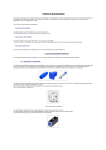
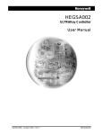
US005‘754960A
United States Patent [19]
[11] Patent Number:
Downs et a1.
[45]
[54] DISPLAY CONSOLE AND USER INTERFACE
FOR
TISITE RF TR
D SYSTEM
[75] Inventors: Stephen R_ Downsz Charles P_ Emma
Date of Patent:
5,754,960
May 19, 1998
OTHER PUBLICATIONS
Jones. ‘The Pye TVT Approach to Audio Controls Sys
terns". International Broadcast Engineer. vol. 6. No. 122. pp.
both of Forest; Satish Kappagantula.
4-6" 8'11‘ Mar" 1975;
Lynchburg an of Va.
Ullah. “Master Sw1tch1ng Control Panel for Broadcast Stud
ies”. ABV Technical Review (Japan). No. 69 (Jul. 1980).
[73] Assigmc; Ericsson Inc" Research Triangle park
Motorola Coverage Guide for Smartnet'l'M System Users (70
NC
page brochure and Table of Contents (pp. l-15).
Trunking Console System Functional Speci?cation. Console
_
Systems. Inc.. Console System Electronics Section 2 (pp.
[21] Appl. No.. 835,689
2_1_2_66).
[22] Filed:
Motorola Centracorn Series II Plus brochure dated Jul. 1.
Feb. 14, 1992
1988 (6 pages).
Related US. Application Data
I
[63]
Motorola System Planner RC-2-37C. Man. 1988. “Centra
.
com Series 11 Control Centers” (pp. 1-42).
cmmnua?o?-in'pal‘l of Sen N0‘ 325,639,13eb- 22, 1991311
Motorola System Planner R4-—2—73A. JuL. 1990. “Centra
No‘ 5’200’954‘
com Series 11 Plus Control Centers" (pp. 1-46).
[51]
Int. Cl.‘5 ..................................................... .. H0413 7/00
Motorola. Inc. Centracom Series 11 PlusTM CR1‘ Console
[52]
US. Cl. ........................ .. 455/508; 455/520; 381/123;
Operator’? Manual (PP- 1—40):Ap1>911¢lix A (PP- 1—6): Glos
379/267
[58]
saw (14» 1—5)
Field Of Search ......................... .. 455/15. 33.1. 53.1.
GB C3” Scri?s- Overview and I"'T°d“c?°“~ Standard Pm
455/541; 379/59. 63. 203. 204. 267. 142;
340/721, 712; 381/123
[56]
‘16° #2-4°°-1°°2-°1~ Jul-- 1983
(List continued on next page.)
References Cited
Primary Examiner—Edward F. Urban
Attorney Agent, or Firm--Nixon & Vanderhye PC.
US. PATENT DOCUMENTS
[57]
3,611,301
10/1971 Parks .................................. .. 340/1725
3,678,391
3,809,910
7/1972 Gough ....................................... 325/55
5/1974 Walker 81 81- Cromwell .......................... n
4,386,118
8/1981 Mgggc?eet et """""""""""" "
new” :1‘ a1‘ ‘
ABSTRACT
A dispatcher console for use in a digitally trunked. multisite
public service radio system. The dispatcher counsel oom
pris6s a personal computer having a co_processor logic
3
board. an audio switching tower. and user I/Os including a
Customized keyboard. display screen. audio speakers. head
4 653,090 3/1937 Haydeny........ .................... .. 379/204
4:698:805 10/1987 Sasuta et a].
...... 370/97
4326954 2/19g3 Molnar ,
56‘ and a "ansmi‘ f°°t Pedal The switching tower mums
audi° c°mmunica?°ns between the °°I1S°1° and multisite
4,866,764
4,901,314
4,924,496
...... 379/368
371/112
the oo-processor board. The customized keyboard is also
connected directly to the co-processor board and has dedi
379/ 142
cated keys for commonly performed functions. The display
iigg?g
,
,
4,947,162
4,961,070
9/1989 Barker, III
2/1990 Lohrbach ..
5/ 1990 Figa et al
52:?“ e1 21
e
switch. The tower is controlled by and connected directly to
screen presents information in a standard format such that
.......... ..
,
8/1990 Kimura
.
340/825 00
_
_
$02113?“her knows prcclscly whcm to ?nd Pamcular
10/1990 Maher a a1. ......................... .. 340/721
1
°“'
(List continued on next page.)
9 Claims, 9 Drawing Sheets
CRT
MONITOR
PERSONAL
1g
coupons
---------------- -»
1
,—\'
£26
3
swim
CWPUYER
:
:
KEVZQRD
"""""
M,
E
MA
1
T0
_
IIJLTIS'T ;
28
AIDCM
COMM
IOWER
|
I
:
_'
:
VOICE :
5,754,960
Page 2
US, PATENT DOCUMENTS
4,964,157
5,548,810
10/1990 Aoshima ............................... .. 379/204
8/1996 Riddell et a1. .......................... .. 455/89
OTHER PUBLICATIONS
4,972,457 11/1990 O‘Sullivan.
ghl'?s ‘ 31
,
,
orst et
379,96
.
............................. ..
GE C3TM Series Console Dispatch Center. Standard Practice
_
5,101,502
3/1992 Felderman et a1. .................. .. 455/531
#2‘403 1003-91‘
5,113,431
5,130,662
5/1992 Hom I
7/1992 Jorgensen a; a1, ,
GE C3TM Senes Mamtenance and Adrmmstratlon Posltlon
(MAP) User Manual. Standard Practice #2,401—1004-01.
5,159,701
10/1992 Barnes et a1. .................... .. 455/541 X
5,169,342 12/1992 Steele et a1. ...... ..
345/146
5,200,954
4/1993 TeeLJretal.
Ch?dress et .......
..
5,223,344
5,241,537
6/1993 Manseu at a],
_ 342/357
8/1993 Gulliford et a1. ....................... .. 370/67
455/331
X
1988‘
, _
_
_ _
1111.. 1988.
GE Mobile Communications C31“ Series Console 16
Plus@ ‘ 0P eratorsas Manual
_
'
_ _
Ericsson GE Mobile Communicatnons 16GEMS Mulusne
Coordinator Maintenance Manual (LBI-38456A).
US. Patent
May 19, 1998
INPUT
QUEUE
EMPTY?
Sheet 6 0f 9
YES
FIG 5’
REMOVE CODE
I FROM QUEUE
SEND COMMANDS
TO A1OCM
802
“803
l
SEND CODE N804
TO PC
GET OUTPUT
MESSAGE
‘\806
FROM DPRAM
_I___
SEND COMMANDS ~30?
TO AIQCM
808 t
SET TONE A509
GENERATOR
5,754,960
US. Patent
May 19, 1993
Sheet 7 of 9
901
READ SCANNER
CHIP SENSOR “902
MEMORY
l
COMPARE NEW
AND OLD
N903
READINGS
l
rmo INPUT
THAT CAUSED N904
INTERRUPT
l
CONVERT tNPUT
POSITION T0
\905
A cool;
i
PUT c005 INTO N906
INPUT QUEUE
R513?
INTERRUPT
FIG 9
5,754,960
5,754,960
1
2
DISPLAY CONSOLE AND USER INTERFACE
FOR MULTISITE RF TRUNKED SYSTEM
speci?cally selecting the groups and individual users to
participate in the call.
The coverage of RF systems has been dramatically
increased by linln'ng several broadcast sites in a multisite
network. Multiple transmitting sites are often necessary to
provide RF communications to all locations within a given
community. Multiple transmitters can accommodate a rural
RELATED APPLICATIONS
This is a continuation-in-part of Ser. No. 825.689 ?led
Feb. 22. 1991. now US Pat. No. 5.200.954. issued Apr. 6.
1993.
community covering many square miles. Similarly. multiple
This application is related to the following co-pending
transmitters may be used in a city having many buildings
that obstruct RF signals. Thus. RF systems are no longer
and commonly assigned US. patent applications:
US. Pat. No. 5.384.854. issued Jan 24. 1995. entitled
“Co-Processor Controlled Switching Apparatus And Method
For Dispatching Console” ?led contemporaneously with this
con?ned to a single transmitter.
The complexity of the system from the view of a dis
patcher console is substantially increased by additional
channels and multiple transmitters. Instead of broadcasting
application. in the name of James L. Teel. In. Stephen R.
Downs. and Charles G. Herndon.
Application Ser. No. 07/658399 ?led Feb. 22. 1991.
which is a continuation-in-part application to Ser. No.
07/573977 entitled “Distributed Multisite Coordination
System” ?led on 28 Aug. 1990 in the name of James L. Teel.
Jr.
US. Pat. No. 5.200.954. issued Apr. 6. 1993. entitled
“Protocol Between Console And RF Trunking System."
US. Pat. No. 5.297.354. issued Feb. 15. 1994. entitled
“Data Protocol And Monitoring System For RF Trunking
Multisite Switch Global Serial Channel."
US. Pat. No. 5.239.538. issued Aug. 24. 1993. entitled
“Controller Architecture For RF Trunking Distributed Mul
tisite Switch.”
US. Pat. No. 5.392.278. issued Feb. 21. 1995. “Distrib
uted Multisite Switch Architecture.”
US. Pat. No. 5.384.776. issued Jan. 24. 1995. entitled
over a single transmitter on a small number of channels.
dispatcher consoles now broadcast over tens. hundreds or
even a thousand channels distributed over several transmit
ters covering a wide area or a large city. A single call can be
broadcast from several sites over as many different channels.
20
Similarly. the complexity of RF systems is also increasing
25
30
35
telecommunication devices. In particular. the invention
relates to a public service radio dispatcher console having a
cathode ray tube (CRT) display. customized keyboard. and
single system handles an entire metropolitan government.
groups can be formed. disassembled and rearranged by the
radio dispatcher. Voice calls can be encrypted for security.
Telephone line calls can be made or received through the
dispatcher console. Moreover. communications can be in the
fonn of data transmission and are no longer just audio
communications.
Dispatchers are facing an increasingly complex RF com
munications systems. This complexity increases the number
of choices to be made by the dispatcher in handling com
munications. Dispatchers cannot be overwhelmed by the
operational aspects of the RF system. The dispatchers must
other user interface devices.
including the police department. ?re department.
With the advent of digitally trunked multisite systems. RF
members covered by different radio broadcast sites. These
FIELD OF THE INVENTION
area that a single system covers have increased substantially.
Since more channels are available. the number of system
users has increased. In the past. an individual system would
have had one police station or one ?re department. Now. a
for that group or individual.
systems can direct calls to individuals or selected group
This invention relates to user interfaces for computerized
INVENTION
Radio dispatchers work with radio communication sys
tems that are becoming increasingly complex. The number
of radio frequency (RF) channels in these systems and the
become available for these systems. Previously. RF systems
had basic key and unkey call terminate functions. In
were made by selecting the appropriate dedicated channel
incorporated by reference.
BACKGROUND AND SUMMARY OF THE
because of numerous additional operation features that have
untrunked systems. calls to selected individuals and groups
“Audio Routing With ATrunked Radio Frequency Multisite
Switc ."
The disclosure of each of these related applications is
‘The dispatcher console must now be informed of the indi
vidual transmitters and channels that are being used. and of
the status of other transmitters and receivers in the system.
45 be free to concentrate on the substance of the calls. any one
of which may be an emergency call. The added features of
a complex RF could become a hinderance to the dispatcher.
unless the dispatcher is able to quickly and easily operate the
dispatch console. Past dispatcher consoles have not been
St]
particularly user friendly.
In the prior art. US. Pat. No. 4.961.070 discloses a “Radio
Console With CRT Display” that allows channel control
windows (CCW). representing selected radio channels. to be
moved about the display. The CCWs present status infor
55
mation on individual sub?eet communication. such as sub
ambulances. hospitals, and other governmental services.
?eet identi?cation. caller id and whether the call is busy. The
CCWs are moved about the display using a computer-mouse
Instead of only communicating with a small number of
interface which also allows the user to operate a menu at the
users. radio dispatchers can now communicate with
bottom of the display screen. It is believed that this patent
discloses the Motorola Centracom 11 Plus dispatcher con
sole.
Another prior art dispatcher console is the Console Dis
hundreds. if not thousands. of system users.
These system users. e.g. mobile radio units. hand-held
radios. other consoles and conventional radio base stations.
are usually grouped by function into agencies. ?eets. and
groups. The dispatcher has the ability to communicate with
patch Center for the C3TM Series Consoles sold by the
assignee Ericsson GE Mobile Communications Inc. The
individual users or these functional groups. In addition. the 65 C31‘M Console is a microprocessor controlled voice switch
dispatcher can patch users and groups together for a speci?c
ing system. The dispatcher workstation includes a control
call. Similarly. the dispatcher can set up a sirnulselect call by
panel of dials. buttons and small displays corresponding to
5 ,754.960
3
4
individual call groups. consoles and other units. Both of
PC computer equipped with VGA graphics. 2 megabytes of
these prior art systems present the dispatcher with compli
cated and non-uniformly displayed information.
The computer uses a proprietary (VRI'X) multi-tasking
RAM. a hard disk and a ?oppy disk for loading software.
operating system published by Ready Systems. Inc. of
Sunnyvale. Calif.
There is a need for dispatcher consoles that displays call
information in an easy-to-comprehend manner. that can be
simply con?gured to suit individual dispatchers. An inven
In addition. the computer has an internal co-processor
logic board 26 that is further described in U.S. Pat. No.
tive dispatch console has been developed that is easy for the
dispatcher to operate through a customized keyboard and
CR1‘ computer display. The dispatch console includes a
standard personal computer (PC) having a novel
co-processor logic board; a customized keyboard connected
to the co-processor board; a CRI‘; devices for audio com
munications such as speakers. earphones. microphones and
a push-to-talk foot pedal; and an audio switching tower for
routing audio between the dispatch console and multisite
switch.
The CRT display screen presents information on ongoing
communications throughout the RF system and historical
information on recently terminated calls. The display is
segmented into functional windows. These windows provide
20
5.384.854 entitled “Co-Processor Controlled Switching
Apparatus and Method for Dispatching Console” and incor
porated by reference above. This co-processor board per
forms the audio and command routing functions necessary
for the dispatcher console. The logic board allows a standard
personal computer to be converted into a dispatcher console.
The customized keyboard 14 is coupled to the logic board
and thereby to the personal computer. A standard keyboard
25 may also be connected to the personal computer. but is
not necessary for the operation of the dispatcher console.
The dispatcher console 10 communicates with the RF
system through a console interface module (CIM) (not
shown) in a multisite switch 28. The multisite switch routes
audio (voice) and data signals throughout the RF system. By
information in a uniform and easy to read manner. For
way of the multisite switch. the dispatcher console commu
example. information on individual communications is
nicates with the trunked and conventional radio systems
shown in an array of communication module windows. Each
coupled to the switch. to telephone lines connected to the
communication module provides information on a speci?c
25 switch and to other dispatch consoles. The dispatch console
call or group such as the caller. volume. and emergency.
and CIM communicate using the messages and the protocols
The customized keyboard has been tailored so that certain
described in further detail in U.S. Pat. No. 5.200.954 entitled
keys are dedicated to speci?c radio functions. For example.
“Protocol Between Console and RF Trunking Switch" and
dedicated keys are provided for transmit. communication
module control. patch and simulselect calls. and telephone
and intercom communications. Common function keys. e.g.
incorporated by reference above.
Individual dispatcher pro?les and entity databases are
F1. F2. are assigned to control various other functions as
loaded into the hard drive of the dispatcher console personal
computer from the MOM-PC 30 via the console-CIM data
needed and in conjunction with display menus.
link to the multisite switch. The MOM-PC is a central
BRIEF DESCRIPTION OF THE DRAWINGS
35
FIG. 1 is a block diagram of a dispatcher console for the
present invention;
FIG. 2 is a display screen for the dispatcher console
Con?guration and Diagnostics Interface" and incorporated
shown in FIG. 1;
FIGS. 3 to 5 illustrate portions of the display screen
shown in FIG. 2;
FIG. 6 is a diagram of the customized keyboard shown in
FIG. 1;
FIG. 7 is a block diagram of the co-processor board in the
personal computer shown in FIG. 1; and
by reference above.
The hard disk and PC-RAM in the personal computer
stores the user pro?le that identi?es among other things. the
dispatcher and the user groups in which the dispatcher
45
DETAIIED DESCRIPTION OF THE DRAWINGS
monitor 12. a customized dispatch keyboard 14 with 101
labeled keys. audio speakers 16 (in the preferred embodi
participates. The pro?le contains information regarding the
preferred console settings for the particular dispatcher and
initial radio settings. As each dispatcher sits down at the
console. such as at the beginning of a new shift. the
FIGS. 8 to 11 are software process ?owcharts showing the
operation of the co-processor board illustrated in FIG. 7.
FIG. 1 shows a dispatcher console 10 having a color CRT
control computer for the RF system and is under the control
of the system operator for the entire RF system. The
operation of the MOM-PC is described in more detail in U.S.
Pat. No. 5.566.388 entitled “RF Trunking Multisite Switch
50
dispatcher calls up the appropriate user pro?le tailored to
that dispatcher. The dispatcher can display the user pro?le
by depressing a function key on the customized keyboard.
The personal computer for the console also stores a
database of user entities. Each entity is an individual trunked
radio unit (e.g. mobile. portable. or console). a radio talk
group. or a conventional radio. There can be several thou
ment each console can have two to twelve speakers). speaker
volume controls 18 underneath each speaker. a microphone 55 sands of radio entities in a multisite system. Accordingly.
20 (or alternatively a headset 21 with volume control 22).
and a foot switch 23 that is a push-to-talk switch. The
dispatcher need look only at the CRI‘ monitor to operate the
console. The dispatch keyboard provides complete control
PC-RAM storage is used. instead of ROM. because the
entity database may be large and changed in real-time. The
entity database includes a record of each entity including the
entity 1]) number. type of entity. e.g. unit and group. home
site. home group and an eight character ASCII name.
The console personal computer saves some database
updates to hard disk immediately. and some updates are
saved only on demand. Thus. the database records are loaded
The speakers. microphone. headset and foot pedal are
from the disk when an operator shift occurs (dispatcher
connected to an audio communications tower 32. The CRT
monitor 12 and an optional standard keyboard 25 are con 65 pro?le change) or at startup. 'Ihe MOM-PC database and
hard disk can be used for back-up storage to the PC-RAM.
nected to a conventional personal computer 24. In the
If the link breaks between the MOM-PC and the console. the
preferred embodiment. the personal computer is an AT-class
over the console to the dispatcher. However. push-to-talk
switches are provided on the microphone 20 and foot pedal
23 for the dispatcher’s convenience.
5 ,754.96()
6
5
console will still have relatively-current database informa
The arrangement of these segments on the screen does not
change. However. the information presented in each window
segment does change. Thus. the dispatcher can become
tion stored on disk.
The dispatcher console relies on the MOM-PC centralized
databases to update and change most of its databases. Since
the personal computer is linked to the MOM-PC via the
mulitsite switch. it has on-line access to these centralized
familiar and comfortable with the arrangement of the seg
ments on the screen. This familiarity allows the dispatcher to
pick out desired information quickly from individual win
databases. The MOM-PC can send an entire database. or
dows because the dispatcher learns precisely where this
information is displayed by knowing the location of each
update information for a database such as a single entity
updates to modify the entity database. New data base
segment.
information can be broadcast on demand by the MOM-PC
operator or requested by a console. such as when the console
comes back on-line after being off-line for a period of time.
One window segment 40 provides a listing of available
entities. e.g. site controllers. groups. units. consoles. con
ventional channels and telephone lines. in the RF system.
Another segment 42 of the display lists the pages of com
munications modules 44 that can be shown. By segregating
the communications modules into pages. the number of
communication modules that can be displayed is drastically
The MOM-PC operator may create multiple dispatcher
user pro?les for each dispatch console. Having multiple
dispatcher user pro?les allow different dispatchers. e.g. a
dispatcher for each work shift. to con?gure the dispatch
console to the individual requirements for each dispatcher
simply by calling up the tailored user pro?le for that
dispatcher. The dispatcher user pro?les are stored in the
increased and the individual modules can be appropriately
grouped by pages.
Communications module windows 44 are arranged con
veniently in columns and rows. These modules provide call
access to individual groups. entities. consoles and telephone
lines in the system. Each communication module is pro
dispatcher console. The dispatcher user pro?les can be set up
and changed only at the MOM-PC.
In addition. each dispatcher console includes an audio
input/output communications module (AIOCM) 32 other
grammed by the dispatcher to represent a particular group.
wise known as a communications tower that links the audio
unit. console. channel. line. etc.. that is available to the
console. To assist in programming the communications
channels from the ClM of the multisite switch 28 with the
25
speakers. microphone and the foot pedal of the dispatcher
module. the available groups. units. consoles. or channels
console. The communications tower is an audio routing
may be displayed in the listing window 40. e.g. a listing of
switch for the dispatcher console. The AICOM is controlled
via link 27 by the co-processor logic board 26 in the personal
sites.
FIG. 3 shows a representative communications module 60
from the communications windows segment 44 of the dis
computer. The communications tower and logic board are
described in more detail in the related U.S. Pat. No. 5.384.
854 entitled “Co-Processor Controlled Switching Apparatus
and Method for Dispatching Console" and incorporated by
reference above.
30
play screen. In the preferred embodiment. each module is
allocated seven rows with nine columns per row. The
individual ?elds in each module are: module page and
position indicator 62. the module name 64. caller name 66.
35
receiving/emergency call indicator 68. console transmit
indicator 70. busy indicator 72 showing that another console
is transmitting to the module id. encrypted call indicator 74.
patch call designator 76. sirnulselect designator 78 and
The overall RF multisite system serves groups of users
and individual users. Each user entity. e.g. mobiles.
personals. other dispatcher consoles. and conventional base
stations in the RF system has an individual identi?cation
volume indicator 80. The background color 81 of the module
is changed to red to signify an emergency call and to green
to signify the select call. The border 82 for the communi
(Logical 11)). Moreover. generally. each mobile radio unit
will be a member of one or more groups. The mobile unit is
programmed with the group identi?cation of its member
group(s) and participates in calls to its group(s). The goups
cations module is highlighted when the module is picked by
can be organized by. for example. police precincts. ?re
department engine units. ambulances and hospitals. Most
depressing the corresponding module key 114. A picked
45
individual users will participate in a call only if the call
involves their group. Individual radio units that are members
of more than one group can scan for calls or the unit can be
set to listen for a particular group to the exclusion of other
groups.
set such that emergency calls are broadcast louder from the
Group identi?cation designations are organized in a four
level hierarchy where (i) the particular group is identified as
dispatcher speakers than other calls. The dispatcher pro?le is
displayed by depressing keys on the console keyboard.
a sub-?eet. (ii) several groups make up a ?eet. (iii) one or
more ?eets make up an agency. and (iv) the total multisite
system is all agencies. Most communications are to particu
lar groups. However. the system allows dispatchers to trans
module is then modi?ed. muted. selected or changed in
volume via keys 118 and 116.
FIG. 4 illustrates a sample dispatcher pro?le 84 that can
be displayed on the screen. The pro?le presents the logical
id for the dispatcher 85. volume settings 86. delay times 87
and other features of the pro?le. The volume levels can be
55
mit to an entire ?eet. agency or system. System wide calls
may be restricted so as to be made only from supervisory
dispatcher consoles.
As shown in FIG. 5. the call history window 52 on the
display presents a chronological list of information on recent
radio calls. The dispatcher can look to the list of recent calls
91 to determine. for example. who is making calls. which
groups have been active. when calls begin and how long
they last. The call history information can be even as little
as a caller identi?cation. This information allows the dis
As shown in FIG. 2 the dispatcher monitor display screen
12 is divided into window segments. These segments pro
patcher to better manage the system and the system users.
Normally. the call history operates in a real time mode 92
vide discrete work areas on the screen. The segments include
an entity listing 40. a page listing 42. communications
where the three most recent calls are displayed in the call
modules 44. status/prompts/messages 46. clock 48. help/call
type/menus S0. and call history 52. These segments display
history window. As a call is terminated. its history comes
information in an organized and regular fashion to the
dispatcher.
65
into view in the call history window. The oldest call dis
played is deleted from the window each time another call
terminates. The dispatcher can freeze the call history win
5 .754.960
7
8
dow to “playback” the previous call. Freezing stops the real
As shown in FIG. 6. the dispatcher inputs commands to
the console through a customized keyboard 14. The key
board includes alphanumeric and function keys. The func
tion keys are not all assigned to static functions. Alterable
time mode at a particular point in time. However. only three
calls can be displayed in the call history window at any one
time.
The dispatch console stores information on more than the
three most recent calls. In the preferred embodiment. infor
mation on 32 calls are stored in the console dispatch
functions keys 102 are assigned varying functions depend
ing upon the operation being performed on the console. The
user can perform a speci?c function on the console by
computer.
depressing the appropriate function key. A dedicated escape
The dispatcher can scroll the call history window through
the history of recent calls by switching the display to the
scrolling mode. The scrolling mode is set up by depressing
the help key to display a menu for the function keys. This
key 104 allows the user to cancel an ongoing operation.
Instruction information regarding the operation of the con
sole and each function key is provided through a help
menu identi?es the function key. e.g. F2. that calls up the
scroll history mode. When in the scrolling mode. the call
history window will display information on any of the stored
calls. The call history is moved forward or backward. i.e.
scrolled. by operation of the up and down arrow keys on the
keyboard. While only three call histories are displayed at
15
20
displayed menu. These default functions include calling up
the user pro?le screen. changing the user pro?le because of
a shift change. signing onto the computer system. and
toggling the call history window. The help key can be used
to display a menu of these default function settings.
The dedicated function keys always perform the same
function and are grouped with other keys of related func
tions. For example. the HELP 106 and ESCAPE 104 keys
25
are grouped with the common control functions 108. In
addition. calls to individual units are made through the
any one time. a much larger number of call histories can be
displayed through scrolling. The dispatcher can revert back
to real time mode on the call history window by depressing
the appropriate function key identi?ed in the call history
window.
The call history window is organized in a bottom-to-top
arrangement with the oldest call at the top and most recent
call (denoted by an asterisk) at the bottom of the window. A
ICALL SEL and ICALL TX keys. 108. that allow the
dispatcher to enter the unit identi?er through the alphanu
meric keypad 117.
header 93 at the top of the call history window shows
column headings identifying each ?eld in the call histories.
The header includes a DATE ?eld that shows the date of the
call. The size of the ?eld underneath the DATE header is
indicated by the mm/dd/yy symbol. Similarly. the time at
which the call began is in the ?led under TIME. the TYPE
of call indicates whether the call was. for example. a group
call. the origin identi?es the site or console of the caller. the
CALLEE identi?es. for example. the group involved in the
call. the CALLER is self-explanatory and DUR is the
duration of the call. The designation REAL TIME 92
30
35
depressing the appropriate key 114. e.g. MDL 3. to pick
45
personal computer.
50
The circular ?le tracks each call by communications
module number. For any period of time. the console may
receive several channel assignment and unkey/drop mes
sages for a variety of calls on various channels. Each
assignment or unkeyldrop message contains an identi?ca
module 3. Once this module has been picked. then the
dispatcher can adjust its volume via volume keys 118. mute
the module. 116. highlight the module for the select speaker
(may be headset). modify the module. 116. or establish (or
clear) an emergency condition for the module 124.
When the module modify key is pressed. a menu screen
is displayed assigning new functions to the alterable func
tions keys 102. These assigned functions allow the dis
patcher to re-program the module to a new unit. group.
then rereads the BIOS timer. The time from the start of the
call is subtracted from the time the call ended to calculate
played
120. A dedicated color coded key 124 sends a push-to-talk
missions to any other module is made by depressing the TX
key 112 corresponding to the communications module.
Through the use of the customized keyboard. the dis
patcher can choose a particular communications module by
upon receipt of a call assignment mes sage. the console takes
from the message the caller ID. callee ID. and site origina
call duration. The digital information corresponding to the
calls to be displayed is converted to ASCII data and dis
muting the console speakers 122; and emergency condition
command over the selected communications module. The
foot switch 23 can also serve this transmit function. Trans
the call history window from command messages from the
multisite switch to the dispatcher console. For example.
Similarly. date and time information is read from the
BIOS timer in the PC computer and also stored in a circular
buffer. The circular buffer holds information on many calls.
32 calls in the preferred embodiment. To calculate length of
call time. the computer waits for an unkeyldrop message and
As can be seen. the more common functions are assigned
dedicated function keys include the establishing of patch
110. sirnulselect 112 and telephone/intercom communica
tions 114; edit control 116 such as paging through screen
displays and cursor and position control on the display;
indicates that the call history window is continually present
ing the three most recently terminated calls.
The dispatcher console obtains the information needed for
tion information and stores it in a circular buffer in the
window on the display accessed via a dedicated help key
106.
The alterable function keys 102 are each assigned a
default function that applies unless over ridden by a screen
55
conventional channel. telephone line. or console.
The co-processor logic board is shown in further detail in
FIG. 7. The heart of the co-processor board is a micropro
cessor 300 which. in the illustrated embodiment. is a
80C152 microprocessor. Firmware executed by the micro
processor 300 is stored in an EPROM 302. The micropro
cessor 300 receives timing signals from a main clock 304.
which also supplies timing signals to a second clock 306.
Pulses from the second clock 306 are utilized by a tone
generator 308. which. in turn. produces the signal TONE for
tion corresponding to one of the module identi?cation
application to the audio tower 32 via an interface cable.
numbers. The computer matches each message to the cor
responding module and stores the information in the appro
Further included in the co-processor system is a dual port
priate circular bu?’er. There is one buffer for each module. 65 RAM (DPRAM 320). The DPRAM 320 handles the com
The call history window tracks all calls regardless of their
munication between the microprocessor 300 and the main
sequence.
processor system in the PC over a bus connector 60.
5 ,754.960
9
10
The co-processor is connected to the audio tower by an
interface cable. The co-processor system has a plurality of
view of DPRAM message are issued to the AIOCM. in step
807. Finally. a check for a new tone command is conducted
in step 808. If a new tone is needed. then the tone generator
is set to sent the tone for a predetermined period of time
inverting and diode protection circuits (lDPCs) 330 for
conditioning input signals received on the interface cable.
The particular input signals applied to each of the IDPCs are
(duration timers are set) in step 809. Once these checks for
commands have been completed. another command check
shown in FIG. 7. and are primarily digital input signals. jack
sense signals. and push-to-talk (P'IT) signals.
begins.
The conditioned signals received from the audio tower 32
As shown in FIG. 9. the scanner chip monitors the
are applied to an appropriate one of three octal tri-state
external inputs. When an input change is detected. the
scanner interrupts the main microprocessor in the
co-processor board in step 901. The microprocessor then
buffers 332 (shown as buffers 332A. 332B and 332C). The
buffers 332 are connected by a buffer data bus 334 and a
buffer control bus 336 to a bu?er scanner 338. In the
illustrated embodiment. the bulfer scanner 338 is a keyboard
scanner chip.
reads the scanner memory to determine which input has
changed. in step 902. This determination is done. in step
903. by comparing the current status of the scanner memory
with the last scanner memory state that is stored and. thus.
The co-processor logic board also includes an analog-to
digital converter (ADC) 350 for converting a signal VU PC
received from the VU meter ampli?er circuit 222 (in the
audio tower 32). Prior to application of the VU PC signal to
the ADC 350. the VU PC signal is conditioned by a
conditioner circuit (CC) 352. The conditioner circuit 352
includes protection diodes and an operational ampli?er.
Selected pins of the microprocessor 300 are connected to
apply signals to the audio tower. In this respect. pins
P5.0—P5.3 are connected to form a bus for carrying a
SELECT signal; pins P41 is connected to carry a STROBE
signal; pin P40 is connected to carry a DATA signal; and
pins P6.0-P6.5 are connected to carry an ADDR signal. The
SELECT. STROBE. DATA and ADDR signals are condi
tioned by respective conditioning circuits 354. 356. 358 and
360. respectively. prior to application to the interface cable.
The conditioning circuits 354. 356. 358 and 360 essentially
are inversion (with pull-up) and diode protection circuits.
In addition to the EPROM 302 and the DPRAM 320. the
co'processor logic board includes random access memory
(RAM) 370. The microprocessor 300 is connected by a
available to the microprocessor. Thus. multiple inputs can
occur while the microprocessor is running other programs.
The inputs will be properly processed when the scanner
interrupt detection routine is conducted.
Once the input (or inputs) that caused the interrupt is
determined. step 904. the microprocessor generates the code
corresponding to that input in step 905. The code (or codes)
is then stored in the input queue in step 906. and the interrupt
routine completed.
25
In this way. the main processing loop (FIG. 8) picks up the
input through a code in the input queue and sends the code
to the input processing routines.
30
An external clock 304 provides pulses to the internal
counter in the co-processor board’s microprocessor. This
internal counter interrupts the microprocessor. e.g. every 10
milliseconds. to trigger a timer service routine. This routine
checks ?ags. decrements active software timers. and checks
35
for active software timers that have been decremented to
zero. Depending on which active software timer reaches
zero. the control logic of the co-processor board issues a key
co-processor data bus 372 to the ADC 350. the buifer
code. updates the VU meter value being displayed in each
scanner 338. the RAM 370. the EPROM 302. and the
communications module on the screen. or changes ?ags and
DPRAM 320. The microprocessor 300 is connected by a
timers related to tone generator sequences.
co-processor address bus 374 to the RAM 370. the EPROM
As shown in FIG. 10. the co-processor board micropro
302. and the DPRAM 320. Eltrther. in conventional manner.
cessor is interrupted by its internal counter in step 1001. The
the microprocessor 300 is connected by a co-processor
interrupt calls up the timer interrupt processing routine
control bus 376 to the ADC 350. the bu?'er scanner 338. the
1000. The microprocessor ?rst checks whether too much
RAM 370. the EPROM 302 and the DPRAM 320.
time has elapsed since receiving the last extended (EXT)
As indicated in FIG. 1. the co-processor keyboard 14 is 45 code. and. if so. re-synchronizes the keyboard routines in
connected to the co-processor. A signal from the
steps 1002 and 1003. If step 1002 yields a yes. then the ?ags
co-processor keyboard is applied to a keyboard input pro
are re-synchronized to be ready for the next code which is
tection circuit 382 prior to application to the microprocessor
expected to be an extended code. The EXT code is the ?rst
300. The keyboard input protection circuit 382 provides
byte of a 2-byte code sent to the co-processor logic board 26
inversion and diode protection functions.
50 each time a key is depressed on the keyboard 14.
The software routines performed by the co-processor
If the repeat timer for a key depression is at zero. step
board monitor the keyboard. scan inputs and other inputs for
1004. then the last key code is resent to the personal
command messages. FIG. 8 shows the over all main pro
computer in step 1005. The dispatcher user will hold down
cessing loop. In step 801. the process checks whether its
a key to signal that a particular key function is to be
input queue is empty. If an input is in the queue. then the
message code is retrieved. step 802. and the commands
necessary in view of the message are issued to the audio
tower (AIOCM) step 803. Similarly. the code is stored in the
DPRAM 320 and an interrupt is sent to the PC micropro
cessor in step 804.
If the input queue is empty (see FIG. 9). step 801. or once
the queue code has been acted upon 803 and the PC
interrupted 804. a check is conducted for an output
command. step 805. If the message number for the retrieved
command with the processed indices for the DPRAM 320
are not equal. then a new command exists. step 806. and it
is retrieved from the DPRAM. The commands necessary in
55
repeated. such as scrolling. Similarly. when the emergency
declare key 120 is depressed. a delay timer. e.g. 1 sec. starts
in order to delay the issuance of the key code to the personal
computer. This delay ensures that the emergency key is held
down for a full second and not inadvertently depressed. In
steps 1006 and 1007. the key code is issued when the delay
timer reaches zero.
The displayed VU meter is updated regularly by the
co-processor. The co-processor decrements a counter each
time it runs its timer interrupt processing routine. in step
1008. When the VU counter equals one (1). step 1009. the
co-processor starts an analog-to-digital conversion (ADC)
from data indicative of the volume level on the select and
5,754,960
12
11
1012. the co-processor converts the new ADC value to a
communication modules presenting information
regarding individual system groups. said communica
logarithmic (LOG) value. step 1013. and sends the log value
to the personal computer. step 1014. The personal computer
then updates the displayed VU meter.
tion modules having a module background color dis
tinctive of a backgound color for said display screen.
the module background color of an individual commu
U0 input. Thus. when the VU counter reaches zero. step
nication module changes when a predetermined key or
key sequence is activated on said keyboard.
2. Adispatcher console as in claim 1 wherein said module
Finally. the timer interrupt processing routine checks
whether the tone sequence is active. step 1015. and. if so.
sets the tone ?ag counters. step 1016. These ?ags are used
to turn tones on/o? and to change the generator frequency
for warble tones. when the timer expires. the ?ags are set so
that the tone sequence continues for a predetermined number
of cycles. Then. the co-processor returns from the timer
interrupt routine until 10 milliseconds later when it is again
interrupted by the logic board’s internal clock counter.
The customized keyboard is connected directly to the
co-processor logic board. When a key is pushed or released.
the keyboard sends a two-byte character sequence to the
co'processor logic board. The ?rst character byte is an
extended code (EXT) that identi?es whether the depressed
key is in a normal or ALT mode. or whether the key has been
released. The second character byte is the key scan code that
identi?es the key on the keyboard. Based on the particular
key codes. the key may be set up with a repeat or delay
15
switch. a dispatcher console operatively coupled to said
multisite switch. said console comprising:
20
counter.
As shown in FIG. 11. the co-processor is interrupted when
it receives the ?rst character byte from a key press or release.
in step 1101. Ifthe co-processor is not waiting for the second
25
tion on numerous terminated audio communications in
said system. and
wherein said display screen is segmented into windows
including a call history window. said call history win
step 1104. ‘The extended code is stored. and the co-processor
waits for the second byte interrupt.
If a second character byte is expected step 1102. then the
dow presenting historical information partially listing
35
upon when the co-processor next executes its main loop
in a scrolling manner on other of said numerous audio
communications.
5. A dispatcher console as in claim 4 wherein said call
history window presents the elapsed time of terminated
communications and wherein said elapsed time is the time
between a call initiation message and a call termination
45
switch. a dispatcher console operatively coupled to said
is presently considered to be the most practical and preferred
embodiment. The invention is not limited to the disclosed
embodiment. It covers various modi?cations and equivalent
arrangements included within the spirit and scope of the
transmitting from said console comprising the following
steps:
appended claims.
console;
wherein said display screen is segmented into windows
including a window of communication modules. said
message as received by said console from said multisite
switch.
6. In a public service radio system including a multisite
multisite switch. said console comprising a personal com
puter including a co-processor board. a display screen hav
ing a window of communication modules. and a keyboard
directly connected to said co-processor board. a method for
The invention has been described in connection with what
What is claimed is:
1. In a public service radio system including a multisite
switch. a dispatcher console operatively coupled to said
multisite switch. said console comprising:
a personal computer including a co-processor board. a
display screen. and a keyboard directly connected to
said co-processor board.
said co-processor board communicating command mes
sages from said computer to an audio switching tower.
said tower routing audio communications between said
multisite switch and audio input/output devices at said
said numerous terminated audio communications. said
call history window being operable in a real time mode
whereby historical information on the most recent
terminated calls is presented. and operable in a scroll
ing mode whereby historical information is presented
key is released. step 1111. then these key timers are
terminated. step 1112.
Unless a delay key has been depressed. step 1113. the
translated PC code is sent to the personal computer. in step
1114. The code from a delayed key is sent after the delay
timer expires. If the transmit key is depressed. step 1115. its
code is loaded into the input queue. step 1116. and then acted
processing routine. Finally. the microprocessor returns from
its interrupt routine. step 1117.
a personal computer including a co-processor board. a
display screen. and a keyboard directly connected to
said co-processor board.
said co-processor board communicating command mes
sages from said computer to an audio switching tower.
said tower routing audio communications between said
multisite switch and audio input/output devices at said
console.
wherein said personal computer stores historical informa
byte of the code. step 1102. then the co-processor reads the
extended code. step 1103. and returns from the interrupt.
scan character code is read from this second byte. step 1105.
and translated into PC code. in step 1106. If a repeating or
delayed key is depressed. then a repeat timer or delay timer
is set as is appropriate. steps 1107 to 1110. Similarly. if the
background color changes to red in a predetermined com
munication module when an emergency key or key sequence
is activated on said keyboard.
3. A dispatcher console as in claim 1 wherein said module
background color changes to green in a select communica
tion module when a predetermined key sequence is acti
vated
4. In a public service radio system including a multisite
a. selecting an individual communication module as the
55
select module by depressing a dedicated key corre
sponding to that individual communication module and
then depressing a module select key;
. transmitting an audio signal over the multisite system
to a group corresponding to the select module by
activating a transmit key; and
c. transmitting an audio signal over the multisite system
to another group other than the select group by depress
ing a transmit key dedicated to a communications
module for that another group.
7. A method as in claim 6 wherein the step of transmitting
to a group corresponding to the select module is initiated by
depressing a key on a microphone at the dispatcher console.
5,754,960
13
8. A method as in claim 6 wherein the step of transmitting
to a group concsponding to "'16 select module is in?ated by
‘kprcssmg a Pedal on a foot “mated Swmh'
9. In a public service radio system including a multisite
switch. a dispatcher console operativcly coupled to said 5
14
presenting historical information partially listing said
numerous terminated audio communications. said call
history window being operable in a real time mode
whereby historical information on the most recent
_
_
multisiw switch said console comprising;
a memory storing historical information on numerous
terminated calls 15 presented. and operable in a scroll
ing mode whereby historical information is presented
terminated audio communications in said system. and
in a scrolling manner on other of said numerous audio
a display screen operatively coupled to said memory. said
display screen being segmented into windows includ- w
ing a call history window. said call history window
communications.
*
*
*
*
*