1
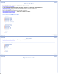
HEGSA002
ULTRAKey Controller
User Manual
518750-2960 - October 2004 – Rev. F
HEMU001007
ISSUE
DATE
REVISIONS
1
September 2000
Initial Release
Rev A
December 2000
Added soft key and hard key default menus, hard key
functions, and SETMAX key code commands.
2
December 2000
Deleted interface box between ULTRAKey and MXAT200.
Rev A
January 2001
Added model KEGSA008, changed references to MAX-1000
model numbers, revised Table 1 and Table 2, added
interface box for extending cable distance between
ULTRAKey and MAX-1000 or for connection to MAX-1000
RDAT200 with DB-15 connector.
Rev B
May 2001
Added a glossary and added the procedure for addressing
KD6 Z-Series domes
Rev C
December 2001
Added Ethernet port setup; added LCD B/L intensity
adjustment menu, corrected screen display for configuring a
soft key, added Icons for the button names, added selecting
a camera, selecting a monitor, programming a view, and
recalling a view; added alphanumeric entry capability for
MX14 or MXSYS04 subrack with an MX128E controller card,
added Appendix A.
Rev D
February 2002
Added Var Freq Buzzer Configuration soft key in Hardware
Configuration Menu
Rev E
December 2003
Deleted reference to models KEGSA004, KEGSA006, and
KEGSA008, revised references to RD530 to KEGS5300;
changed startup screen from Ultrak logo to Honeywell logo
(PCN 1486); added default keycode commands 143-145;
revised the Hard Key/func menu; revised config user menu;
updated the worldwide offices contact page, reformatted.
Rev F
October 2004
518750-2960
Rev. F
PCN 1837 Rebranding/Firmware Revision
ii
HEMU001007
10/15/04
FCC COMPLIANCE STATEMENT
INFORMATION TO THE USER: This equipment has been tested and found to comply
with the limits for a Class A digital device, pursuant to part 15 of the FCC rules. These
limits are designed to provide reasonable protection against harmful interference when
the equipment is operated in a commercial environment. This equipment generates,
uses, and can radiate radio frequency energy and, if not installed and used in
accordance with the instruction manual, may cause harmful interference to radio
communications. Operation of this equipment in a residential area is likely to cause
harmful interference in which case the user will be required to correct the interference at
his own expense.
CAUTION: Changes or modifications not expressly approved by the party responsible
for compliance could void the user’s authority to operate the equipment.
This Class A digital apparatus complies with Canadian ICES-003.
Cet appareil numérique de la Classe A est conforme à la norme NMB-003 du Canada.
USERS OF THE PRODUCT ARE RESPONSIBLE FOR CHECKING AND
COMPLYING WITH ALL FEDERAL, STATE, AND LOCAL LAWS AND
STATUTES CONCERNING THE MONITORING AND RECORDING OF
VIDEO AND AUDIO SIGNALS. HONEYWELL VIDEO SYSTEMS SHALL
NOT BE HELD RESPONSIBLE FOR THE USE OF THIS PRODUCT IN
VIOLATION OF CURRENT LAWS AND STATUTES.
518750-2960
Rev. F
iii
HEMU001007
10/15/04
Declaration Of Conformity
We,
Honeywell International Inc.
165 Eileen Way
P.O. Box 9035
Syosset, NY 11791,
U.S.A.
declare that our product(s):
Model number(s):
HEGSA002
Type of equipment:
CCTV Controller
are in conformity with the following standards:
EMC directive, 89/336/EEC
EN 61000-6-4:2001 Emissions standard and EN50130-4:1995+A1:1998 Immunity
standard
EN 55022 Radiated Class A, EN 55022 Conducted Class A
EN 610000-4-2 ESD, EN 61000-4-3 RF fields, EN 61000-4-4 EFT/burst, EN 61000-4-5
Surge,
EN 61000-4-6 RF-conducted, EN 610004-11 Dips/interruptions/variations
Safety directive, 73/23/EEC
EN 60065:1998 Safety requirements for audio, video and similar electronics apparatus
518750-2960
Rev. F
iv
HEMU001007
10/15/04
IMPORTANT SAFEGUARDS
1.
READ INSTRUCTIONS – All safety and operating instructions should be read before the unit is
operated.
2.
RETAIN INSTRUCTIONS – The safety and operating instructions should be retained for future
reference.
3.
HEED WARNINGS – All warnings on the unit and in the operating instructions should be adhered
to.
4.
FOLLOW INSTRUCTIONS – All operating and use instructions should be followed.
5.
CLEANING – Unplug the unit from the outlet before cleaning. Do not use liquid cleaners or
aerosol cleaners. Use a damp cloth for cleaning.
6.
ATTACHMENTS – Do not use attachments not recommended by the product manufacturer as
they may result in the risk of fire, electric shock, or injury to persons.
7.
WATER AND MOISTURE – Do not use this unit near water or in an unprotected outdoor
installation, or any area which is classified as a wet location.
8.
ACCESSORIES - Do not place this product on an unstable cart, stand, tripod,
bracket, or table. The product may fall, causing serious injury to a child or adult and
serious damage to the equipment. Use only with a cart, stand, tripod, bracket, or
table recommended by the manufacturer, or sold with the product. Any mounting of
the product should follow the manufacturer’s instructions and should use a mounting
accessory recommended by the manufacturer. Wall or shelf mounting should follow the
manufacturer’s instructions and should use a mounting kit approved by the manufacturer.
9.
A product and cart combination should be moved with care. Quick stops, excessive force, and
uneven surfaces may cause the product and cart combination to overturn.
10.
VENTILATION - Slots and openings in the cabinet and the back or bottom are provided for
ventilation and to ensure reliable operation of the equipment and to protect it from overheating.
These openings must not be blocked or covered. The openings should never be blocked by
placing the product on a bed, sofa, rug, or other similar surface. Equipment should never be
placed near or over a radiator or heat register. This product should not be placed in a built-in
installation, such as a bookcase or rack unless proper ventilation is provided or the manufacturer’s
instructions have been adhered to.
11.
POWER SOURCES – This product should be operated only from the type of power source
indicated on the marking label. If you are not sure of the type of power supplied to your home,
consult your product dealer or local power company. For products designed to operate from
battery power or other sources, refer to the operating instructions.
12.
GROUNDING OR POLARIZATION – The power supply supplied with this unit may be equipped
with a polarized alternating-current line plug (a plug having one blade wider than the other). This
plug will fit into the power outlet only one way. This is a safety feature. If you are unable to insert
the plug fully into the outlet, try reversing the plug. If the plug should still fail to fit, contact your
electrician to replace your obsolete outlet. Do not defeat the safety purpose of the polarized plug.
518750-2960
Rev. F
v
HEMU001007
10/15/04
IMPORTANT SAFEGUARDS, CONTINUED
13.
OVERLOADING – Do not overload outlets and extension cords as this can result in a risk of fire or
electric shock.
14.
POWER-CORD PROTECTION – Power supply cords should be routed so that they are not likely
to be walked on or pinched by items placed upon or against them, paying particular attention to
cords and plugs, convenience receptacles, and the point where they exit from the monitor.
15.
OBJECT AND LIQUID ENTRY – Never push objects of any kind into this unit through openings as
they may touch dangerous voltage points or short-out parts that could result in a fire or electric
shock. Never spill liquid of any kind on the unit.
16.
SERVICING – Do not attempt to service this unit yourself as opening or removing covers may
expose you to dangerous voltage or other hazards. Refer all servicing to qualified service
personnel.
17.
DAMAGE REQUIRING SERVICE – Unplug the unit from the outlet and refer servicing to qualified
service personnel under the following conditions:
a. When the power-supply cord or plug is damaged.
b. If liquid has been spilled, or objects have fallen into the unit.
c.
If the unit has been exposed to rain or water.
d. If the unit does not operate normally by following the operating instructions. Adjust only those
controls that are covered by the operating instructions as an improper adjustment of other
controls may result in damage and will often require extensive work by a qualified technician to
restore the unit to its normal operation.
e. If the unit has been dropped or the enclosure has been damaged.
f.
When the unit exhibits a distinct change in performance - this indicates a need for service.
18.
REPLACEMENT PARTS – When replacement parts are required, be sure the service technician
has used replacement parts specified by the manufacturer or have the same characteristics as the
original part. Unauthorized substitutions may result in fire, electric shock or other hazards.
19.
SAFETY CHECK – Upon completion of any service or repairs to this unit, ask the service
technician to perform safety checks to determine that the unit is in proper operating condition.
20.
LIGHTNING AND POWER LINE SURGES – For added protection of this unit during a lightning
storm, or when it is left unattended and unused for long periods of time, unplug it from the wall
outlet and disconnect the cable system. This will prevent damage to the unit due to lightning and
power-line surges.
21.
HEAT – The product should be situated away from heat sources such as radiators, heat registers,
stoves, or other products (including amplifiers) that produce heat.
22.
INSTALLATION – Do not install the unit in an extremely hot or humid location, or in a place
subject to dust or mechanical vibration. The unit is not designed to be waterproof. Exposure to
rain or water may damage the unit.
518750-2960
Rev. F
vi
HEMU001007
10/15/04
IMPORTANT SAFEGUARDS, CONTINUED
23.
WALL OR CEILING MOUNTING – The product should be mounted to a wall or ceiling only as
recommended by the manufacturer
518750-2960
Rev. F
vii
HEMU001007
10/15/04
EXPLANATION OF GRAPHICAL SYMBOLS
The lightning flash with arrowhead symbol within an equilateral triangle is intended to
alert the user to the presence of uninsulated "dangerous voltage" within the product's
enclosure that may be of sufficient magnitude to constitute a risk of electric shock to
persons.
The exclamation point within an equilateral triangle is intended to alert the user to the
presence of important operating and maintenance (servicing) instruction in the literature
accompanying the product.
CAUTION
CAUTION
RISK OF ELECTRIC SHOCK
DO NOT OPEN
CAUTION: TO REDUCE THE RISK OF ELECTRIC SHOCK,
DO NOT REMOVE COVER (OR BACK).
NO USER-SERVICEABLE PARTS INSIDE.
REFER SERVICING TO QUALIFIED SERVICE PERSONNEL.
WARNING
WARNING: TO REDUCE THE RISK OF FIRE OR ELECTRIC SHOCK, DO
NOT EXPOSE THIS PRODUCT TO RAIN OR MOISTURE.
WARNING: DO NOT INSERT ANY METALLIC OBJECT THROUGH
VENTILATION GRILLS THIS PRODUCT TO RAIN OR MOISTURE.
WARNING: THIS UNIT MUST BE OPERATED WITH A PROPERLY
GROUNDED 3-PIN CONNECTION.
NON-OBSERVANCE OF THIS STANDARD PRACTICE MAY RESULT IN A
STATIC ELECTRICITY BUILD-UP THAT MAY RESULT IN AN ELECTRIC
SHOCK WHEN EXTERNAL CONNECTIONS ARE TOUCHED.
518750-2960
Rev. F
viii
HEMU001007
10/15/04
GLOSSARY
TERM
DEFINITION
ULTRAKey
MAX-1000 keyboard with LCD touch screen. Model number HEGSA002.
Soft Keys
Keys programmed on an LCD touch screen menu.
Hard Keys
Keys with physical buttons.
MAX1000
MAX-1000 CCTV Management System.
MXAT200
MAX-1000 Control computer.
Menu
A menu defined on the ULTRAKey LCD touch screen.
MAX Key Code
The numeric key identifier to be sent to the MAX-1000 MXAT200X
controller. Range = 1 to 999.
Start up menu
The "home" menu on the ULTRAKey LCD touch screen.
Keyboard address
The identifying address assigned to an ULTRAKey keyboard. Range = 199.
PreShot (View/Preset)
A PreShot/View/Preset is a camera/lens position including, pan, tilt, zoom,
and focus that can be given a title and stored in a “smart” pan and tilt unit.
Up to 100 PreShots can be programmed and stored in each
HD6iUltraDome.
PreShots are programmed using a system controller. An operator can
send a dome to a programmed PreShot using the controller.
518750-2960
Rev. F
ix
HEMU001007
10/15/04
NOTES:
518750-2960
Rev. F
x
HEMU001007
10/15/04
TABLE OF CONTENTS
SECTION 1: INTRODUCTION ................................................................................................................1
1.1
PRODUCT DESCRIPTION ............................................................................................................1
1.2
HARDWARE FEATURES ...............................................................................................................1
SECTION 2: INSTALLATION ..................................................................................................................3
2.1
CONNECTIONS ............................................................................................................................3
SECTION 3: SETUP AND OPERATION..................................................................................................7
3.1
PROGRAMMING ...........................................................................................................................7
3.2
CONVERTING FROM THE HEGS5300 (RD530) KEYBOARD TO THE ULTRAKEY KEYBOARD .7
3.3
OPERATION ..................................................................................................................................7
3.4
RUN MODE ...................................................................................................................................8
3.5
3.4.1
Selection Numbers .........................................................................................................17
3.4.2
Selecting a monitor ........................................................................................................18
3.4.3
Selecting a Camera ........................................................................................................18
3.4.4
Controlling a PTZ camera ..............................................................................................19
3.4.5
3.4.6
Programming a PreShot (View)......................................................................................20
Sending a Camera to a View (PreShot) .........................................................................20
CONFIG MODE ...........................................................................................................................21
3.5.1
Hardware Configuration .................................................................................................22
3.5.2
Manage Users ................................................................................................................27
3.5.3
Config Hard Keys ...........................................................................................................29
3.5.4
Check Hardware.............................................................................................................33
3.5.5
Config User Menus.........................................................................................................34
3.5.6
Select Language ............................................................................................................39
3.5.7
Load Defaults .................................................................................................................39
3.5.8
Download Firmware .......................................................................................................40
3.5.9
Uploading/Downloading Data Files and Custom Settings ............................................44
3.5.9.1 Upload Data (Send File) from ULTRAKey ............................................................47
3.5.9.2 Download Data to ULTRAKey (Receive Any File) ................................................49
3.5.10 General Info....................................................................................................................50
3.6
ALPHANUMERIC ENTRY MODE ................................................................................................51
SECTION 4: MAINTENANCE ...............................................................................................................53
4.1
PREVENTIVE MAINTENANCE ....................................................................................................53
4.2
TROUBLESHOOTING .................................................................................................................53
4.2.1
4.3
Booting with Default Configuration Parameters .............................................................53
RETURNING EQUIPMENT TO HONEYWELL VIDEO SYSTEMS................................................54
518750-2960
Rev. F
xi
HEMU001007
10/15/04
TABLE OF CONTENTS, CONTINUED
APPENDIX A: KEY CODES...................................................................................................................55
A.1
MX14 CONTROLLER AND MXSYS04 SUBRACK WITH AN MX128E CONTROLLER CARD .....55
LIST OF FIGURES
Figure 1: Front View .....................................................................................................................................1
Figure 2: Rear View ......................................................................................................................................3
Figure 3: Interface Box for Extending Distance Between ULTRAKey and MAX-1000 MXAT200................4
Figure 4: Interface Box for Connecting to MXAT200 with DB-15 Connector ...............................................4
LIST OF TABLES
Table 1: Index For MAX-1000 Key Codes .................................................................................................10
Table 2: Default MAX-1000 Key Code Commands ....................................................................................11
Table 3: ULTRAKey Hard Key Functions ....................................................................................................13
Table 4. COM Port Available Settings ........................................................................................................24
Table 5. COM Port Default Settings ...........................................................................................................24
518750-2960
Rev. F
xii
HEMU001007
10/15/04
PURCHASE INFORMATION
Date Purchased:
Serial Number:
Location Installed:
518750-2960
Rev. F
xiii
HEMU001007
10/15/04
NOTES:
518750-2960
Rev. F
xiv
HEMU001007
10/15/04
SECTION 1:
INTRODUCTION
1.1
PRODUCT DESCRIPTION
The ULTRAKey is an operator interface device that connects to the MAX-1000 MXAT200
controller. The ULTRAKey is a user-friendly touch screen interface for controlling
cameras, monitors, switchers, VCRs, etc. The interface has the capability of providing a
descriptive touch screen soft key for each camera configured in the system. The
ULTRAKey is interchangeable with a HEGS5300 (RD530) keyboard.
1.2
HARDWARE FEATURES
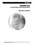
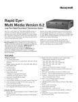
Figure 1: Front View
The ULTRAKey uses a 1/4 VGA LCD display that provides soft touch descriptive keys.
Soft keys are displayed in menus on the LCD screen. The menus are accessible either
from other soft keys or by pressing a hard key (mechanical key) on the keyboard. Status
messages from the MAX-1000 controller are displayed in a message box at the top of
the LCD display.
A joystick is provided for the pan, tilt, and zoom control of PTZ cameras. The joystick
resolution can be set for high (26 increments) or low (5 increments) using the touch
screen hardware configuration menu.
Two jog/shuttle controls are also provided. The response to the jog/shuttles is defined
in the SETMAX program.
518750-2960
Rev. F
1
HEMU001007
10/15/04
1.2 HARDWARE FEATURES, CONTINUED
Hard keys are provided for sending keystroke commands to the MXAT200 controller or
selecting menus on the LCD display. The function keys can be programmed using the
touch screen.
Numeric Keypad – the numeric keypad is used to enter numbers in programming
screens and entering camera numbers, monitor numbers, and other device numbers.
518750-2960
Rev. F
2
HEMU001007
10/15/04
SECTION 2:
INSTALLATION
2.1
CONNECTIONS
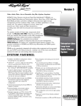
COM 2
RS-485 Output
(In lieu of
RS-232 port)
RS-232 Output
(In lieu of
RS-485 port)
Input Power
9-12V @1.2A
COM 3
RS-232
Serial Port
COM 1
RS-485 Output
Not Used
AT Keyboard
Ethernet Connection
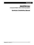
Figure 2: Rear View
Power Supply – Model HEGSA002 is provided with a U.S. power cord, part number
849518-0261.
An AT-keyboard can be connected to the keyboard port. The AT-keyboard can be used
for entering alphanumeric text in the configuration menus.
COM1 (RS485 output port) is not used.
COM2 (RS232 serial port) on the ULTRAKey connects to the MAX-1000 MXAT200
controller to exchange commands and data. (The RS232 port on the back of the
ULTRAKey is aligned with the center of the VCR pause and record keys.) A 6-foot (2meter) coiled cable for connection between the ULTRAKey and the MXAT200 is
provided. Plug one end of the coiled cable into COM2 and the other end into any of the
ports on the MXAT200 configured for an RD530 keyboard.
An interface box is provided if the distance between the ULTRAKey and the MXAT200 is
greater than 6 feet (~2 meters). Plug the 6-foot coiled cable into one of the RJ-11
connectors on the interface box. Using standard telephone cable with RJ-11 connectors
on both ends, plug one end into an RJ-11 connector on the interface box and the other
end into the MXAT200. Refer to figure 3.
518750-2960
Rev. F
3
HEMU001007
10/15/04
2.1 CONNECTIONS, CONTINUED
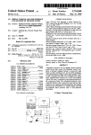
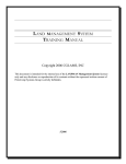
Figure 3: Interface Box for Extending Distance Between
ULTRAKey and MAX-1000 MXAT200
NOTE: The interface box can also be used if the ULTRAKey is interfacing to an MAX1000 RDAT200 controller that requires a DB-15 connector. Plug one end of the coiled
cable into COM2 (RS232) on the ULTRAKey and the other end into one of the RJ-11
jacks on the interface box. A flipped cable with bare leads on one end and a DB-15
connector on the other end is required. Connect the DB-15 connector to the MAX-1000
RDAT200 controller and the bare leads to the terminals on the interface box. Refer to the
following table for the terminal pin-outs of the interface box.
Figure 4: Interface Box for Connecting to MXAT200 with DB-15 Connector
518750-2960
Rev. F
4
HEMU001007
10/15/04
2.1 CONNECTIONS, CONTINUED
The COM3 (DB-9 Male) RS-232 Port connects to a PC serial port for downloading and
uploading the ULTRAKey firmware and databases. The cable, part number 8495180401, for connection between the ULTRAKey and a PC is provided. Refer to paragraphs
3.5.8 and 3.5.9.
Ethernet – This RJ45 jack is for connection to a network.
518750-2960
Rev. F
5
HEMU001007
10/15/04
NOTES:
518750-2960
Rev. F
6
HEMU001007
10/15/04
SECTION 3:
SETUP AND OPERATION
3.1
PROGRAMMING
The person responsible for system configuration can define soft keys for the LCD
screen, and can configure the actions of the hard keys. Soft keys and hard keys can be
configured to do either or both of the following:
1. Send one or more keystroke commands to the MAX-1000 controller. The keystroke
commands are defined in the SETMAX program.
2. Access a menu of soft keys on the LCD screen.
Refer to paragraph 3.5 (CONFIG mode) for programming procedures.
3.2
CONVERTING FROM THE HEGS5300 (KEGS5300) KEYBOARD TO THE
ULTRAKEY KEYBOARD
The ULTRAKey's command interface to the MAX-1000 controller is the same as for the
RD530 keyboard. The ULTRAKey sends key press and release information to the MAX1000 controller. To use the capabilities of the ULTRAKey, the SETMAX program must be
version 4.30B or higher, which recognizes up to 999 key commands. The keyboard
must then be programmed to send command strings containing one or more key
numbers when the soft key or hard key is pressed.
The ULTRAKey also contains jog and shuttle key definitions that need to be incorporated
into the SETMAX programming if these controls are to be used.
3.3
OPERATION
When power is applied to the keyboard, it boots the firmware.
NOTE: Booting the firmware can take up to 30 seconds. After the firmware has
booted, the Honeywell logo is displayed on the LCD screen for 2 seconds. If the LCD
screen is not touched during this interval, it automatically enters the RUN mode. If you
touch the display, it enters the Configuration mode.
518750-2960
Rev. F
7
HEMU001007
10/15/04
3.3
OPERATION, CONTINUED
The following keystroke combinations will return you to the Honeywell logo screen.
Essentially, these commands exit the Run mode and reboot the ULTRAKey firmware:
ALT (hard key) + HOME (soft key)
ALT + CLR + FUNC (all hard keys)
3.4
RUN MODE
The first default user screen (after the Honeywell logo) in RUN mode is shown below.
The LCD displays ULTRAKey OFF-LINE in the status box at the top of the screen until
communication is sent to the MAX1000 controller or received from the MAX1000
controller. This message is also displayed if the ULTRAKey is connected to a MX14
controller or a MXSYS04 subrack with MX128E controller card and communication is lost
between the two devices. The left or right side of the status box can be pressed to
cause the MAX1000 controller to send different lines of status display. The status
messages are programmable in the SETMAX program.
NOTE: The soft keys
(except Home and Back)
can be reprogrammed in the
configuration mode.
For complete operator information on how to select and control devices, refer to the
MAX1000 CCTV Management System Operators Manual.
When configured hard keys or soft keys are pressed, they will do one or both of the
following.
1. Send one or more key commands to the MAX-1000 MXAT200. The SETMAX
program defines the key commands. There are 999 key commands available.
2. Access another menu of soft keys.
518750-2960
Rev. F
8
HEMU001007
10/15/04
3.4 RUN MODE, CONTINUED
To view the second page of the startup screen, press the More soft key
The soft keys in the
default menus send
MAX1000 key code
commands or call up
another menu depending
on how they are
programmed. Refer to
Table 1 for a listing of the
key code commands.
The following default menus are programmed for the soft keys in the startup menus:
Soft Key: User macro
Soft Key: Menu
The Menu soft key
displays four menus for
setting up peripheral
equipment. The menus
for the MAX-1000 Setup
and Dome Setup are
shown below
518750-2960
Rev. F
9
HEMU001007
10/15/04
3.4 RUN MODE, CONTINUED
Soft Key: MAX-1000 Setup
Soft Key: Dome Setup
Tables 1 and 2 show the default MAX-1000 key code commands.
Table 1 is a general index.
Table 2 is a listing of the defined key code commands.
Table 1: Index For
MAX-1000 Key Codes
518750-2960
Rev. F
1 - 199
MAX
200 - 299
ASSIGNABLE
300 - 999
RESERVED
10
HEMU001007
10/15/04
3.4 RUN MODE, CONTINUED
Table 2: Default MAX-1000 Key Code Commands
Key Code
Function
Key Code
1
Alarm Acknowledge
32
2
33-36
3
Scan
37
Group 13
4
Halt
38
Group 14
5
Pause
39
Group 15
40
Group 16
Max Menu
6
7
Group 1
41
8
Group 2
42
9
Group 3
43
Mux
10
Group 4
44
Full
11
Alarm Clear
45
Multi screen
12
46
13
Insert
47
VCR
14
Delete
48
Function
15
Set
49
Undo
50
Alternate
Door open
16
17
Group 5
51
18
Group 6
52
19
Group 7
53
Print select
20
Group 8
54
Freeze
21
User Macro
55
Print color
56
Print B/W
22
23
Left Arrow
57
Mon A
24
Lock
58
Mon B
25
Right Arrow
59
Mon C
60
Mon D
26
518750-2960
Rev. F
Function
27
Group 9
61
MONITOR SELECT
28
Group 10
62
Keypad key 1
29
Group 11
63
Keypad key 2
30
Group 12
64
Keypad key 3
31
Dome Menu
65
UP arrow
11
HEMU001007
10/15/04
TABLE 2: Default MAX-1000 Key Code Commands, Continued
Key Code
Function
Key Code
Function
66
Keypad key 4
99
PAN RIGHT
67
Keypad key 5
100
SCROLL UP
68
Keypad key 6
101
SCROLL DOWN
69
DOWN arrow
102
70
Keypad key 7
103
JOG 1 RIGHT
71
Keypad key 8
104
JOG 1 LEFT
72
Keypad key 9
105
SHUTTLE 1 RIGHT
73
CAMERA select
106
SHUTTLE 1 LEFT
74
View
107
JOG 2 RIGHT
75
Keypad key 0
108
JOG 2 LEFT
76
ENTER
109
SHUTTLE 2 RIGHT
77
Stop
110
SHUTTLE 2 LEFT
78
Play
111
Exit Programming
79
Record
112
Group 17
80
Rewind
113
Group 18
81
Pause
114
Group 19
82
F.Forward
115
Group 20
83
Text
116
Group 21
84
Dub
117
Group 22
85
Review
118
Group 23
86
ZOOM IN
119
87
ZOOM OUT
120
Monitor E
88
FOCUS FAR
121
Monitor F
89
FOCUS NEAR
122
Monitor G
90
IRIS OPEN
123
Monitor H
91
IRIS CLOSE
124
92
Night Shot
125
93
Auto Exposure
126
94
PTZ Call
127
95
Tour
128
96
TILT UP
129
97
TILT DOWN
130
Logging VCR
98
PAN LEFT
131
Standby VCR
518750-2960
Rev. F
12
BLC
HEMU001007
10/15/04
3.4 RUN MODE, CONTINUED
TABLE 2: DEFAULT MAX-1000 KEY CODE COMMANDS, CONTINUED
Key Code
Function
Key Code
Function
132
140
Mux menu
133
141
Quad menu
134
142
135
143
RapidDome Man
Color
136
2x2
144
RapidDome Auto
Focus
137
3x3
145
RapidDome Auto Flip
138
4x4
146-199
139
PIP
200-299
ASSIGNABLE
Table 3 defines the default programming for the ULTRAKey hard keys.
The keys can be reprogrammed in the configuration mode.
Table 3: ULTRAKey Hard Key Functions
HARD KEY
Key Code
CAMERA
73
MONITOR
61
MUX
43
Mux
RECORDER
-
Recorder
ALTERNATE
50
PTZ CALL
94
TOUR
95
VIEW
74
DOWN ARROW
69
UP ARROW
65
Tour
SEQ
3
Sequence
Func
-
Function
PLAY
78
STOP
77
FOCUS +
89
IRIS +
90
RECORD
518750-2960
Rev. F
ALT
Menu
79
13
HEMU001007
10/15/04
3.4 RUN MODE, CONTINUED
TABLE 3: ULTRAKEY HARD KEY FUNCTIONS, CONTINUED
HARD KEY
PAUSE
Key Code
81
REVIEW
85
FOCUS -
88
IRIS -
91
PRINT
53
Print
DUB
84
Dub
ALARM ACK
1
Alarm
RIGHT ARROW
SET
LEFT ARROW
518750-2960
Rev. F
Menu
Review
25
15
23
ENTER
76
1
62
2
63
3
64
4
66
5
67
6
68
7
70
8
71
9
72
0
75
CLEAR
14
HEMU001007
10/15/04
3.4 RUN MODE, CONTINUED
The following default menus are programmed for the ULTRAKey hard keys. The menus
for the hard keys can be reprogrammed in the configuration mode.
Hard Key: alarm ack
Hard key: dub
Hard key: print
518750-2960
Rev. F
15
HEMU001007
10/15/04
3.4 RUN MODE, CONTINUED
Hard Key: review
Hard Key: func
Hard Key: func
518750-2960
Rev. F
16
HEMU001007
10/15/04
3.4 RUN MODE, CONTINUED
Hard Key: VCR (recorder)
Hard Key: MUX
3.4.1 Selection Numbers
For all CCTV keyboard operations, an associated numeric entry is required to select and
control devices in the system. For example, when selecting a camera, the camera
number must be entered on the numeric keypad. If the maximum camera number used
in the system, for example, is Camera 20, the CCTV system would always expect a 2digit camera number to be entered when selecting any camera. To select camera 19,
the operator must enter 19 as a 1 followed by a 9. If the operator wishes to select
camera 1, the operator can enter the camera number two ways.
518750-2960
Rev. F
1
Enter
0
1
(If the required number of digits is pressed, the Enter key is not
required)
17
HEMU001007
10/15/04
3.4 RUN MODE, CONTINUED
3.4.2 Selecting a monitor
To change the current picture on a video display monitor, a monitor must first be
selected.
Press the Mon key followed by the desired monitor number.
Example: Select monitor 3 (in a system with 10 monitors).
3
Enter
OR
0
3
NOTE: This example assumes the monitor icon button is programmed to execute key
code 61 (Monitor Select).
3.4.3 Selecting a Camera
NOTE: A monitor must be selected first.
Press the Camera key followed by the desired camera number, then Enter if required.
1
5
Enter
1
5
OR
0
NOTE: This example assumes the camera icon button is programmed to execute the
default key code 73 (Camera Select).
To scroll through the available cameras, press the key to select the next camera.
Press the key to select the previous camera. The jog can be rotated clockwise to
select the next camera. The jog can be rotated counterclockwise to select the previous
camera.
518750-2960
Rev. F
18
HEMU001007
10/15/04
3.4 RUN MODE, CONTINUED
3.4.4 Controlling a PTZ camera
To operate a PTZ camera, you must meet the following criteria:
1. A monitor must be selected;
2. The monitor must be displaying the PTZ camera;
3. The camera must have PTZ capability
PAN LEFT
Push (and hold) the joystick toward the left.
Release the joystick to halt the pan function.
PAN RIGHT
Push (and hold) the joystick toward the right.
Release the joystick to halt the pan function.
TILT UP
Push (and hold) the joystick up away from yourself.
Release the joystick to halt the tilt up function.
TILT DOWN
Push (and hold) the joystick down toward yourself.
Release the joystick to halt the tilt down function.
NOTE: The tilt up and down functions may be reversed, depending on your system’s
configuration.
If the PTZ camera is equipped with manual iris and/or a zoom lens, the following PTZ
functions apply.
518750-2960
Rev. F
IRIS +
Press (and hold) the iris + button to open the lens iris until the
desired iris setting is achieved, then release the button.
IRIS -
Press (and hold) the iris - button to close the lens iris until the
desired iris setting is achieved, then release the button.
ZOOM IN
Press (and hold) the zoom in key until the desired setting is
achieved, then release the button.
ZOOM OUT
Press (and hold) the zoom out key until the desired setting is
achieved, then release the button.
FOCUS -
Press (and hold) the focus – key to “far” focus the lens. Releasing
the key halts the focus function.
FOCUS +
Press (and hold) the focus + key to “near” focus the lens.
Releasing the key halts the focus function.
19
HEMU001007
10/15/04
3.4 RUN MODE, CONTINUED
3.4.5 Programming a PreShot (View)
NOTE: Access to programming PTZ preset positions may be denied to some operators.
To program a camera VIEW (PTZ position), you must meet the following criteria:
1. A monitor must currently be selected;
2. The monitor must be displaying the desired camera;
3. The desired camera must be a PTZ camera with VIEW (preset) capability
Using the camera PTZ functions, move to the desired position of the new view.
Perform the following procedure to save the desired position.
Press VIEW then SET.
Press the view number (00-99).
NOTE: Usually only the first ten (00-09) views are available to the keyboard operator.
3.4.6 Sending a Camera to a View (PreShot)
To send a camera to a view, the following criteria must be met:
1. A monitor must be selected;
2. The monitor must be displaying the desired camera;
3. The desired camera must have PTZ with View capability.
Press the VIEW key then the view number (00-99).
518750-2960
Rev. F
20
HEMU001007
10/15/04
3.5
CONFIG MODE
To access the CONFIG mode from the RUN mode, press alt+Home to reboot the
controller. Touch the Honeywell logo to enter the Configuration mode.
Press the Configure soft key to access the
configuration menu.
To enter the configuration mode, the user
must first enter a valid password and press
Enter. The factory set password is 1111.
After a valid password is entered,
the Configuration menu is displayed.
Press a soft key to access the menus
for each configuration function or press QUIT
to exit the Configuration menu
518750-2960
Rev. F
21
HEMU001007
10/15/04
3.5 CONFIG MODE, CONTINUED
3.5.1 Hardware Configuration
Press the Hardware Config soft key to
access the hardware configuration
options.
+Contrast = 29 - press this soft key
to increase the contrast of the LCD
display.
- Contrast = 29 – press this soft key to
decrease the contrast of the LCD
display.
After setting the contrast to the desired
level, press the SAVE soft key.
LCD B/L = 4 – press this soft key to set the LCD backlight intensity. There are four
settings (1, 2, 3, & 4) with 1 being the lowest intensity and 4 being the highest intensity.
Note: this adjustment only applies to board 470502-1030, Rev. A or later.
Calibrate TouchScrn – press this soft
key to calibrate the touchscreen.
Touch the screen using a small
diameter, soft, blunt instrument (such
as a pencil eraser) as stated in the
message to calibrate the screen.
Press the QUIT soft key to exit the
calibration menu without changing the
settings or press the SAVE soft key to
save the settings and exit the calibration
menu. If you select SAVE, a message
(an example is shown to the right) is
displayed showing the new settings.
Press YES to change the settings.
Press NO to exit the calibration menu.
518750-2960
Rev. F
22
HEMU001007
10/15/04
3.5 CONFIG MODE, CONTINUED
Keyboard Addr = 1 – press this soft key to
change the address of the ULTRAKey. Each
keyboard in the system must have a unique
address between 1 and 99 corresponding to
the keyboard address as defined in the
SETMAX program.
Enter the desired number using the numeric
soft keys or the numeric keypad, then press
the Enter soft key. Use the Bkspc soft key to
delete a number(s) entered in error. Press the
Quit soft key to exit the keyboard address
menu without changing the address.
After entering a new keyboard address, press the SAVE soft key in the Hardware Config
menu. A message, “Save to Flash?” is displayed. Press YES to save the new keyboard
address; press NO to exit without saving the new address to flash memory.
Port Settings – press this soft key to define
the communication settings for COM1, COM2,
COM3, or Ethernet.
Press the desired soft key (COM1, COM2,
COM3, or Ethernet) to define the
communication settings.
NOTE: The communication settings must be
the same as the equipment connected to the
port.
Example: Press COM 1
Pressing the soft key toggles between the
available options. Refer to Tables 1 and 2 for
the available and default port settings
518750-2960
Rev. F
23
HEMU001007
10/15/04
3.5 CONFIG MODE, CONTINUED
Table 4. COM Port Available Settings
Soft Key
COM 1 & COM 2
Available Settings
COM 3
Available Settings
Type
RD530
None
Debug
File Trans
None
Parity
Even
Odd
None
Even
Odd
None
Baud Rate
9600
19200
38400
9600
19200
38400
Data Bits
5
6
7
8
8
Stop Bits
2
1
1
The settings required for the MAX-1000 (ULTRAKey) are:
even parity, 19,200 baud rate, 7 data bits, and 1 stop bit.
Table 5. COM Port Default Settings
Soft Key
COM1
COM2
COM3 (DB-9 RS-232 Port)
Type
None
RD530
Debug
Parity
NA
Even
None
Baud Rate
NA
19.2K
9600
Data Bits
NA
7
8
Stop Bits
NA
1
1
*NA = Not Applicable
518750-2960
Rev. F
24
HEMU001007
10/15/04
3.5 CONFIG MODE, CONTINUED
When you press the Ethernet soft key, the
following screen is displayed:
CAUTION: Contact Your Network Administrator
Before Changing Network ID Settings. Incompatible
IP Settings Can Be Detrimental To The Operation Of
Your Network.
To change the IP Address, Subnet Mask, Default Gateway, and Sys. Cntl.
(System Controller) IP Address to match your existing network settings, press the
corresponding soft key for each setting.
NOTE: The Default Gateway and Sys. Cntl. IP Address fields can be disabled.
To disable one of these fields, enter 000.000.000.000.
The following is an example of what is
displayed on the screen when an Ethernet
Setup soft key is pressed.
Enter the 12-digit address using the soft key
numeric keypad, the numeric keypad on the
ULTRAKey, or a QWERTY keyboard
connected to the ULTRAKey.
NOTE: Leading zeros must be entered for
numbers (within addresses) with less than
three (3) digits. For example: 128.129.39.75
must be entered as 128129039075
Press the SAVE soft key to save the settings
you entered or press the QUIT soft key to exit
the port settings menu without saving the
settings.
If you pressed SAVE, the following message is
displayed.
518750-2960
Rev. F
25
HEMU001007
10/15/04
3.5 CONFIG MODE, CONTINUED
Press the YES soft key to save the settings or
press NO to exit the port settings menu. If you
press YES, the message DATA SAVED is
displayed.
Joystick Res=High – press this soft key to change the joystick (pan and tilt functions)
resolution to high or low. High = 26 increments, Low = 5 increments. The soft key
toggles between the options. After changing the joystick resolution, press the SAVE soft
key in the Hardware Config menu.
Var Buzzer Freq = ON – This soft key selection is available in firmware version 3.01 and
later. The default is ON to support the buzzer driver on circuit board 470502-1030, Rev.
A. If firmware version 3.01 or later is used with an earlier revision circuit board, the
buzzer driver for the older circuit may be selected by changing the Var Buzzer Freq to
OFF. Pressing this soft key toggles the buzzer frequency from variable (On) and fixed
(Off).
Zero Joystick – press this soft key to zero the joystick. This function electronically
centers the pan, tilt, and zoom positions of the joystick. This function should be
executed with the joystick in its neutral position. This function is executed automatically
on power-up.
KeyClick = HIGH – press this soft key to change the sound the ULTRAKey makes when
you press any soft key, programmed hard key, move the joystick or jog/shuttles . The
available options are low, high, or off. If you change the KeyClick setting, press the
SAVE soft key in the Hardware Config Menu. Note: The Key Click setting in SETMAX
must be enabled for the soft and hard key clicks to be operational, and the Joystick click
setting in SETMAX must be enabled for the joystick and jog/shuttle audible feedback to
be operational.
SAVE – Press this soft key to save all hardware configuration settings. The message,
“Save to Flash?” is displayed. Press YES to save the settings to flash memory; press
NO to exit without saving settings. If you pressed yes, the message, “Data Saved”, is
displayed.
QUIT – Press this soft key to exit the hardware configuration settings.
CAUTION: Save any changes before exiting or settings
will be lost.
518750-2960
Rev. F
26
HEMU001007
10/15/04
3.5 CONFIG MODE, CONTINUED
3.5.2 Manage Users
Press the Manage Users soft key to add
users, delete users, or change user privileges
or password.
The programming soft keys are the six
buttons on the left side.
The programmed users are displayed in the
two right columns.
NOTE: The ULTK Admin user is for factory use and cannot be deleted. The USER
Admin is the factory defined user with password 1111. This user can be deleted, but
you must create another User ID with Admin privileges, log in as the new user, then
delete USER Admin. If you are logged in as password 1111 (USER Admin), you cannot
delete yourself
Add User – press this soft key to add a new
user
1. Using the touch screen or an AT-keyboard, press the characters (up to 4) to enter
the User ID. Use the up and down arrows on the touch screen to access more keys
(lower case letters, symbols, etc.). To enter numeric values, use the numeric
keypad. To delete characters from the end of the User ID, press the Bksp soft key;
to delete all characters, press the Clear soft key.
2. Press the Enter soft key to enter the
new User ID. The ULTRAKey requires
you to provide a system privilege level User, Lead, or Admin.
518750-2960
Rev. F
27
HEMU001007
10/15/04
3.5 CONFIG MODE, CONTINUED
1. Enter the Users privilege level by pressing the appropriate soft key.
User allows the operator full control and programming capabilities less
Manage Users capability.
Lead allows the operator full control and programming capabilities less Manage
Users capability.
Admin allows the operator full control and programming capabilities of the
ULTRAKey.
2. Enter the User’s password. The
password must be a minimum of 4
numbers to up to 10 numbers
maximum. Use the soft keys on the
LCD display, the numeric keypad, or the
AT-keyboard to enter the password.
3. Press the Enter soft key
4. You must confirm the password by
entering the same password again.
Press the Enter soft key.
Delete User – Press the User you want to delete by pressing the User soft key (the User
key should be outlined), then press the Delete User soft key. A message to confirm
deleting the selected user is displayed. Press YES to delete the user; press NO to
cancel the operation. Note: you cannot delete yourself.
Change Privilege – Press the User’s soft key (the User key should be outlined), then
press the Change Privilege soft key. A message to confirm changing the selected user’s
privilege is displayed. Press YES to change the privilege; press NO to cancel the
operation. If you press YES, the privilege screen is displayed. Select the appropriate
privilege by pressing the soft key and then press Enter.
518750-2960
Rev. F
28
HEMU001007
10/15/04
3.5 CONFIG MODE, CONTINUED
Change Password – Press the User’s soft key (the User key should be outlined), then
press the Change Password soft key. The message, “Are you sure you want to change
the password for User ID?”, is displayed. Answer Yes or No. If you answer No, you exit
the change password menu. If you answer Yes, the LCD prompts you to enter the new
password. Enter the new password using the numeric soft keys or the numeric keypad,
then press Enter. The LCD prompts you to confirm the new password, then press Enter.
Save – Press this soft key to save all user entries (new and changed).
Quit – Press this soft key to exit the Manage Users menu.
CAUTION: Save new entries and user changes prior to
quitting.
3.5.3 Config Hard Keys
Press the Config Hard Keys soft key (from
the CONFIGURATION menu) to program the
response for the function (hard) keys.
1. Press the Edit Properties soft key.
2. Press the hard key you want to
configure or change the current
configuration
For example, if you pressed the VCR
hard key, the following menu is
displayed.
You can program the hard key to send a keystroke command to the MXAT200
controller or call up another menu or both. The keystroke command must be
programmed in the MXAT200 using SETMAX.
3. To program one or more (up to 10) keystroke commands, press the MAX Key soft
key. The first key command, step #1, is
displayed.
NOTE: The same procedures used to
program a hard key are used to edit the
configuration of a hard key.
518750-2960
Rev. F
29
HEMU001007
10/15/04
3.5 CONFIG MODE, CONTINUED
a. Select a keystroke command for step #1.
1)
If there are keystroke commands listed, you can select from the listing by
highlighting the Key# and Key Name. To view more of the listing, press
the soft up and down arrow keys or the soft Pg Up and Pg Dn keys.
2)
To go to a specific key # in the list, press the Goto Key# soft key. Enter
the key# and press Enter. If the key# does not exist in the listing, the
highlight goes to the closest number in the listing.
3)
To add a keystroke command to the list, refer to paragraph c below.
When the desired command is highlighted, press the Select Action soft
key, then the OK soft key. The message “Key Action Changed” is
displayed on the LCD display.
The display automatically goes to step #2.
b. Program a keystroke command for step #2 or press OK to end programming
MAX keystroke commands.
If two or more steps are programmed, the user can view the previous step in the
sequence by pressing the Prev Step soft key or the next step in the sequence
by pressing the Next Step soft key.
If two or more steps are programmed, the user can view the previous step in the
sequence by pressing the Prev Step soft key or the next step in the sequence
by pressing the Next Step soft key.
To delete a step in the command sequence, display the step to be deleted, then
press the Del Actn soft key. A message confirming deleting the action is
displayed. Press YES to delete the action; Press NO to cancel the operation. If
you press Yes, the step is deleted and all steps after the deleted step are moved
up one step. For example, if you have five steps programmed and you delete
step 3. Step 4 moves to step 3 and step 5 moves to step 4. Step 5 is no longer
programmed.
To insert a step in the command sequence, highlight the desired keystroke
command, then press the Ins Actn soft key. A message, “Key Action Inserted”
is displayed. The action is inserted before the currently displayed step. For
example, to insert a step between steps 2 and 3, display step #3 by pressing
the Prev Step or Next Step soft keys. If you press the Ins Actn soft key while
viewing step #3, the key# that is highlighted is inserted as step #3, and step 3
becomes step 4, step 4 becomes step 5, etc.
518750-2960
Rev. F
30
HEMU001007
10/15/04
3.5 CONFIG MODE, CONTINUED
c.
To add a keystroke command to the listing, press the New Key soft key.
1)
Enter the keystroke command number (1-999).
NOTE: The keystroke command numbers must correspond to the
commands programmed in the MXAT200 controller using the SETMAX
program.
d. Enter a name for the command. Using the soft up and down arrow keys or the
jog control to scroll through the available characters on the keyboard. You can
also use the numeric keypad to enter numbers.
1.
Press Enter.
2.
Perform step a above to select the new command for the hard key.
e. To delete a keystroke command from the listing, highlight the key# and name,
then press the Del Key soft key. Note: if the key is being used, an error
message is displayed, “Unable to delete key code. Key being used.” Press OK
to exit the error message. If the key code has been selected or created during
this programming session, you must save a new selection for the hard key
before you can delete the key action. Exit the programming menus, then reenter the hard key programming screen and delete the key action.
f.
To change the name of a keystroke command, press the Edit Name soft key,
enter a new name, and press OK. The new name appears in the listing.
g. Press the OK soft key to save programming or press the Cancel soft key to exit
menu without saving. Note: Changes made with the Edit Name, New Key,
and Del Key soft keys do not revert back if cancel is pressed.
4. To program a Menu Action,
press the Menu soft key
518750-2960
Rev. F
31
HEMU001007
10/15/04
3.5 CONFIG MODE, CONTINUED
a. If there are Menus listed, you can select from the listing by highlighting the
Menu Name. To view more of the listing, press the soft up and down arrow
keys or the soft Pg Up and Pg Dn keys. When the menu is highlighted, press
the Select Action soft key, then the OK soft key.
b. To add a new menu to the listing,
press the New Menu soft key
c.
1)
Enter the name of the new menu. Use the soft up and down arrow keys to
view more characters. You can also use the numeric keypad for entering
numbers or the AT-keyboard for entering alphanumeric characters. Use
the Bksp and Clear key for keystroke errors.
2)
Press the Enter soft key. The new Menu name appears in the listing.
The new menu automatically gets assign to the hard key you are editing.
To delete a menu from the listing, highlight the menu name, then press the Del
Menu soft key. Note: if the menu is being used, an error message is displayed,
“Unable to delete menu. Menu being used.” Press OK to exit the error
message. If the menu has been selected or created during this programming
session, you must save a new selection for the hard key before you can delete
the menu. Exit the programming menus, then re-enter the menu programming
screen and delete the menu.
d. To edit a menu’s name, press the Edit Name soft key. Edit the name by
pressing the Bksp key to clear letters from the end of the name, press the clear
key to clear all letters, then add letters using the soft characters on the display or
use the AT-keyboard. Note: you cannot edit the name of the Startup Menu.
e. To delete a menu action from a hard key, press the Delete Action soft key.
f.
Press the OK soft key to save programming. Press the Cancel soft key to exit
programming without saving.
NOTE: Changes made with the Edit Name, New Menu, or Del Menu soft keys
do not revert back if Cancel is pressed.
518750-2960
Rev. F
32
HEMU001007
10/15/04
3.5 CONFIG MODE, CONTINUED
5. To edit a menu, press the Edit Menu soft key. Refer to paragraph 3.5.5 for
programming a menu.
6. Press the OK soft key to save programming.
Press the Cancel soft key to exit programming without saving.
7. To verify the actions of the hard key, press the Execute Actions soft key.
a. Press the hard key on the controller. Verify the MAX key command actions you
programmed occur.
NOTE: The action (key command) must be programmed in the MXAT200
controller.
8. Continue programming hard keys or press the Quit soft key to exit the Hard Key
Configuration menu.
3.5.4 Check Hardware
The Check Hardware soft key is a diagnostic tool to verify operation of the hard keys, the
jogs and shuttles, and the joystick
Press the Check Hardware soft key. A screen is displayed with a status box for each
control function or hard key on the controller. Press each hard key and operate the
jogs, shuttles, and joystick. Verify the box for each function fills with bars (joystick and
jog/shuttles) or a block appears (hard key) as you perform the function.
To exit the diagnostic screen, press the touch screen anywhere.
518750-2960
Rev. F
33
HEMU001007
10/15/04
3.5 CONFIG MODE, CONTINUED
3.5.5 Config User Menus
Press the Config User Menus from the Configuration screen to add, delete, or edit soft
keys. The following is an example of a Startup Menu. Your startup menu may vary, i.e.
you may have a custom screen or no soft keys defined other than the Home, Back, and
Status Box.
When configuring the soft keys and menus, you can edit an existing key by holding “alt”,
then pressing the soft key you wish to edit. You can send the key command (to the
MAX-1000 controller) associated with a soft key by holding the “func” key and then
pressing the soft key.
The first row (Home and Status Box) and the first key (Back) in the second row are not
programmable. All other areas of the screen are programmable.
1. To edit an existing soft key, press the alt key and the soft key.
To create a new soft key, touch a blank space on the LCD display.
For example, pressing alt+ the Group 1 soft key in the above screen,
opens the following configuration menu.
518750-2960
Rev. F
34
HEMU001007
10/15/04
3.5 CONFIG MODE, CONTINUED
In the status box, the Menu name where the soft key resides is displayed and the
location of the soft key within the menu is displayed
a. The button size can be one, two, or three button widths (providing there is blank
space next to the soft key on the display). The screen only displays the possible
size(s) for the space. To select a button size, press the desired button size on
the screen.
b. The text displayed on the menu for the soft key is programmable. There can be
two lines of text (Top Text and/or Bottom Text). The text is centered on the
button horizontally and vertically.
NOTE: If the text is wider than the key, the text will be truncated.
only one line of text, it is centered vertically on the key.
c.
If there is
1)
To enter the top line of text, press the Top Text soft key.
2)
Enter the desired name for the soft key by pressing the character soft keys
on the display. Use the soft up and down arrow keys or the jogs to scroll
through the keyboard for more characters. An AT-keyboard can also be
used or numbers can also be entered using the numeric keypad on the
ULTRAKey.
3)
Press the soft Enter key to save the text
4)
To enter the bottom line of text, press the Bottom Text soft key.
5)
Perform steps 2 and 3 for the Bottom Text.
The button action can be one or more MAX key commands (up to 10) and/or a
Menu command.
1)
To program one or
more (up to 10)
keystroke commands,
press the MAX Key soft
key. The first key
command, step #1, is
displayed.
NOTE: The same
procedures are used to
program a hard key or
to edit the configuration
of a hard key.
518750-2960
Rev. F
35
HEMU001007
10/15/04
3.5 CONFIG MODE, CONTINUED
a)
Select a keystroke command for step #1.
i)
If there are keystroke commands listed, you can select from the
listing by highlighting the Key# and Key Name. To view more
of the listing, press the soft up and down arrow keys or the
soft Pg Up and Pg Dn keys.
ii)
To go to a specific key # in the list, press the Goto Key# soft
key. Enter the key# and press Enter. If the key# does not exist
in the listing, the highlight goes to the closest number in the
listing.
iii) To add a keystroke command to the list, refer to paragraph c
below.
When the desired command is highlighted, press the Select Action
soft key, then the OK soft key. The message “Key Action Changed”
is displayed on the LCD display.
The display automatically goes to step #2.
b)
Program a keystroke command for step #2 or press OK to end
programming MAX keystroke commands. If two or more steps are
programmed, the user can view the previous step in the sequence
by pressing the Prev Step soft key or the next step in the sequence
by pressing the Next Step soft key.
To delete a step in the command sequence, display the step to be
deleted, then press the Del Actn soft key. A message confirming
deleting the action is displayed. Press YES to delete the action;
Press NO to cancel the operation. If you press YES, the step is
deleted and all steps after the deleted step are moved up one step.
For example, if you have five steps programmed and you delete
step 3. Step 4 moves to step 3 and step 5 moves to step 4. Step 5
is no longer programmed.
To insert a step in the command sequence, highlight the desired
keystroke command, then press the Ins Actn soft key. A message,
“Key Action Inserted” is displayed. The action is inserted before
the currently displayed step. For example, to insert a step between
steps 2 and 3, display step #3 by pressing the Prev Step or Next
Step soft keys. If you press the Ins Actn soft key while viewing step
#3, the key# that is highlighted is inserted as step #3, and step 3
becomes step 4, step 4 becomes step 5, etc.
518750-2960
Rev. F
36
HEMU001007
10/15/04
3.5 CONFIG MODE, CONTINUED
c).
To add a keystroke command to the listing, press the New Key soft
key.
i)
Enter the keystroke command number (1-999). Note: The
keystroke command numbers must correspond to the
commands programmed in the MXAT200 controller using the
SETMAX program.
ii)
Enter a name for the command. Using the soft up and down
arrow keys or the jog control to scroll through the available
characters on the keyboard. You can also use the numeric
keypad to enter numbers.
iii) Press Enter.
iv) Perform step a) above to select the new command for the hard
key.
2.
d.
To delete a keystroke command from the listing, highlight the key#
and name, then press the Del Key soft key. Note: if the key is
being used, an error message is displayed, “Unable to delete key
code. Key being used.” Press OK to exit the error message. If the
key code has been selected or created during this programming
session, you must save a new selection for the hard key before you
can delete the key action. Exit the programming menus, then reenter the hard key programming screen and delete the key action.
e.
To change the name of a keystroke command, press the Edit Name
soft key, enter a new name, and press OK. The new name appears
in the listing.
f.
Press the OK soft key to save programming or press the Cancel soft
key to exit menu without saving. Note: Changes made with the
Edit Name, New Key, and Del Key soft keys do not revert back if
cancel is pressed.
To program a Menu Action, press the Menu soft key.
A menu is displayed for programming the Menu Action
a.
518750-2960
Rev. F
If there are Menus listed, you can select from the listing by
highlighting the Menu Name. To view more of the listing, press the
soft up and down arrow keys or the soft Pg Up and Pg Dn keys.
When the menu is highlighted, press the Select Action soft key,
then the OK soft key.
37
HEMU001007
10/15/04
3.5 CONFIG MODE, CONTINUED
b.
To add a new menu to the listing, press the New Menu soft key.
i)
Enter the name of the new menu. Use the soft up and down
arrow keys or the jogs to view more characters. You can also
use an AT-keyboard for entering characters or the numeric
keypad on the ULTRAKey for entering numbers. Use the Bksp
and Clear key for keystroke errors.
ii)
Press the Enter soft key. A message, “Menu Selection
Changed” is displayed. The new Menu name appears in the
listing.
c.
To delete a menu from the listing, highlight the menu and press the
Del Menu soft key. There are two menus, the StartupMenu and the
AlphanumericEntry menu that cannot be deleted. Also, if the menu
is assigned to a soft key, the following message is displayed.
“ERROR: Unable to delete menu. Menu being used.” Press OK.
d.
To edit a menu’s name, press the Edit Name soft key, enter the new
name and press OK. Use the Bksp to delete letters from the end of
the name or use the Clear key to delete all letters. Note: The
Alphanumeric Entry and StartupMenu menus cannot be renamed or
edited. The new name appears in the listing.
e.
To delete a menu action from a soft key, press the Delete Action soft
key. A message confirming the deletion is displayed. Press YES
to delete the menu action; press NO to cancel the deletion.
f.
Press the OK soft key to save programming or press the Cancel soft
key to exit menu without saving.
NOTE: Changes made with the Edit Name, New Menu, and Del
Menu soft keys do not revert back if cancel is pressed.
3.
Press the OK soft key to save programming.
Press the Cancel soft key to exit programming without saving.
d. To remove a button from a menu, press the Delete Button soft key.
e. If you want to copy this button and insert it into another menu, press the Copy
Button soft key. This copies the button to a holding file (much like a Windows
clipboard). You can then paste the button into another menu.
f.
To save the programming for the soft key, press the OK soft key.
2. Press alt+home soft key to return to the previous menu.
518750-2960
Rev. F
38
HEMU001007
10/15/04
3.5 CONFIG MODE, CONTINUED
3.5.6 Select Language
The Select Language soft key is for future use. If
you press the Select Language soft key, the
following message is displayed.
The message disappears after 2 seconds
3.5.7 Load Defaults
To load the factory set defaults, press the Load Defaults soft key in the
CONFIGURATION menu. This returns the ULTRAKey to the default menu and hard key
configuration embedded in the firmware. This is normally a nominal configuration with
default hard key definitions and no defined menus. However, for custom versions of the
ULTRAKey, the default configuration may be a fully functional configuration that is hardcoded in the ULTRAKey firmware.
When you press the Load Defaults soft
key, the following message is displayed.
Press Done after reading the screen.
You will be asked if you want to load
default menu and hard key configuration.
Press NO to exit restoring defaults.
Press YES to restore the default
configuration. If you select YES, the system
asks if you want to save the defaults to flash
memory.
When asked to save the defaults to flash
memory:
Press NO to only restore the defaults until you power down the ULTRAKey. This allows
you to work with the default settings, but not permanently change the firmware back to
the default settings.
Select YES to restore the defaults to flash memory.
CAUTION: This action deletes all custom programming
and returns the firmware to all default settings as soon as
‘Yes’ is pressed.
518750-2960
Rev. F
39
HEMU001007
10/15/04
3.5 CONFIG MODE, CONTINUED
3.5.8 Download Firmware
The firmware can be downloaded from a PC to the ULTRAKey. The PC must be
connected to the ULTRAKey on COM 3 (RS-232 DB-9). The PC must have the file
transfer software loaded. The communication settings of the port on the PC must be the
same as the communication settings of COM 3 on the ULTRAKey. The recommended
transfer baud rate is 38,400.
CAUTION: Prior to downloading new firmware, upload
your data base files to a PC. Data base files may be
corrupted when firmware is downloaded. Refer to
paragraph 3.5.9.
1. Set the ULTRAKey port settings for COM3 to File Trans and set the baud rate to the
desired setting. Refer to paragraphs 3.5, 3.5.1, and Table 2. Power down the
ULTRAKey and power it back up.
NOTE: If COM3 is already set to File Trans, you do not need to power the unit
down.
2. Run the file transfer software on your PC. The software is stored on the 3-1/2” floppy
disk provided in the zip lock bag with the manual. The file name for the transfer
software is filexfer.exe. There are two files (rom.vxWorks.bin and rom.appl.bin) on
the floppy for the firmware. You can copy the files from the floppy to your hard drive
on your computer or you can run the software and download the files from the
floppy disk.
NOTE:
If you copy the files to your hard drive and run the transfer software from
your hard drive, the filexfer.exe can be copied to a location of your choice. The
filexfer.ini file must be copied to your Windows directory (Windows 95/98) or Winnt
directory (WindowsNT).
3. Run the file transfer software by double left-clicking on filexfer.exe. The following
window opens:
518750-2960
Rev. F
40
HEMU001007
10/15/04
3.5 CONFIG MODE, CONTINUED
4. Left click on Settings or press Alt+S on the PC keyboard. Left click on Port or
press P on the PC keyboard.
5. Left click on TARGET to define the communication settings for the PC serial port
connected to the ULTRAKey.
a. Set the Port: field to the port on the PC connected to the ULTRAKey. Click on
the down arrow beside the Port: field to display the available settings.
b. Set the Baud: field to 38400 (recommended). This can be set to any of the
available settings as long as COM3 on the ULTRAKey is set at the same rate.
c.
Set the Parity, Data Bits, and Stop Bits. Again, these settings must match the
settings of COM3 on the ULTRAKey. The data bits and stop bits must be set at
8 and 1, respectively.
d. Left click on OK to save settings.
518750-2960
Rev. F
41
HEMU001007
10/15/04
3.5 CONFIG MODE, CONTINUED
6. Left click on Settings or press Alt+S on the PC
keyboard.
Left click on Select Device.
a. Select ULTRAKey by pointing to the radio
button beside ULTRAKey. When selected, it
should appear as shown above.
b. Left click on OK.
7. Left click on Settings or press Alt+S on the PC keyboard.
Left click on Select Path.
a. Select the Disk where the firmware files are located, for example a: if you are
using the floppy or c: if you copied the files to your hard drive. The disk must be
highlighted in the window.
b. Select the Directory (if applicable) where the firmware files are located on the
disk. Note: If you download from the floppy, the files are stored in the root
directory so you will not need to select a directory.
The path you selected is displayed in the Path: field.
c.
518750-2960
Rev. F
Left click on OK.
42
HEMU001007
10/15/04
3.5 CONFIG MODE, CONTINUED
8. Left click on File or press Alt+F on the PC keyboard. Left click on File Transfer.
There are two files that must be downloaded; the operating system and the
application software. The two files are:
Operating System = rom.vxWorks.bin
Application Software = rom.appl.bin
WARNING: Both Files Must Be Downloaded Prior To
Removing Power To The Controller. The Controller
Will Not Be Functional If Power Is Removed Before
Both Files Are Downloaded.
Download one file at a time. Left click on the file to select it. The file is selected
when it is highlighted as shown below. The file being downloaded is displayed in
the Path: field
9. Press the Upload/Download soft key in the CONFIGURATION MENU on the
ULTRAKey. The SEND and RECEIVE Menu is displayed.
a. Press the Receive Any File soft key. The message, “You have chosen to receive
data”, is displayed. Press YES to continue receiving data. Press NO to end the
operation.
NOTE: You have approximately one (1) minute to begin downloading a file after
pressing YES before the unit times out and returns to the Send & Receive Menu.
518750-2960
Rev. F
43
HEMU001007
10/15/04
3.5 CONFIG MODE, CONTINUED
10. Left click on Download File in the PC file transfer window.
A counter to show the file transfer is displayed in the PC window.
If you downloaded the operating system file (rom.vxWorks.bin), the message,
“Download of RTOS firmware complete”, is displayed on the ULTRAKey when the
download is complete.
If you downloaded the application firmware file (rom.appl.bin), the message,
“Download of Application firmware complete”, is displayed on the ULTRAKey when
the download is complete.
After the download is complete, the display on the ULTRAKey returns to the SEND
and RECEIVE Menu.
11. You must power down the ULTRAKey and power it back up to use the new firmware.
WARNING: Make Sure You Have Downloaded Both
Files Before Powering Down Unit. Wait Until The
Download Complete Message Is Displayed Before
Powering Down The Unit. The Flash Memory May
Become Corrupted If Power Is Removed Too Soon
After Downloading Firmware.
Note: If the configuration file is corrupted and the ULTRAKey does not come back
online, refer to paragraph 4.2.1 for booting the ULTRAKey using the factory default
configuration and erasing the configuration data.
3.5.9 Uploading/Downloading Data Files and Custom Settings
The user custom settings and data files can be uploaded to a PC for backup or can be
downloaded from a PC to the ULTRAKey.
The PC must be connected to the ULTRAKey on COM 3 (RS-232 DB-9). The PC must
have the file transfer software loaded and the communication settings of the port on the
PC must be the same as the communication settings of COM 3 on the ULTRAKey. The
recommended transfer baud rate is 38,400. COM 3 on the ULTRAKey must be set for
File Transfer.
1. Set the ULTRAKey port settings for COM3 to File Trans and set the baud rate to the
desired setting. Refer to paragraphs 3.5, 3.5.1, and table 2. Power down the
ULTRAKey and power it back up.
NOTE:
down
518750-2960
Rev. F
If COM3 is already set to File Trans, you do not need to power the unit
44
HEMU001007
10/15/04
3.5 CONFIG MODE, CONTINUED
2. Press the Upload Download soft key in the CONFIGURATION menu on the
ULTRAKey.
3. Run the file transfer software on your PC. The file transfer software is located on the
3-1/2” floppy disk in the zip lock bag provided with the unit. The file name is
filexfer.exe.
NOTE: The software can be run from the floppy disk or the files can be copied to
your hard drive and run from the hard drive. If you chose to copy the files to your
hard drive, the file filexfer.exe can be copied to the disk and directory of your choice.
The filexfer.ini file must be copied to your Windows directory (Windows 95/98) or
your Winnt directory (WindowsNT).
4. Double click on filexfer.exe. The following window opens.
518750-2960
Rev. F
45
HEMU001007
10/15/04
3.5 CONFIG MODE, CONTINUED
5. Left click on Settings or press Alt+S on the PC keyboard. Left click on Port or
press P on the PC keyboard.
6. Left click on TARGET to define the communication settings for the COM port. The
settings must match the communication settings for COM3 in the ULTRAKey.
a. Set the Port: field to the port on the PC where the ULTRAKey is connected.
Click on the down arrow beside the Port: field to display the available settings.
b. Set the Baud: field to 38400 (recommended). This can be set to any of the
available settings as long as COM3 on the ULTRAKey is set at the same rate.
c.
Set the Parity, Data Bits, and Stop Bits. Again, these settings must match the
settings of COM3 on the ULTRAKey. The data bits and stop bits must be set
at 8 and 1, respectively.
d. Left click on OK to save settings.
518750-2960
Rev. F
46
HEMU001007
10/15/04
3.5 CONFIG MODE, CONTINUED
7. Left click on Settings or press Alt+S on the PC keyboard.
Left click on Select Device.
a. Select ULTRAKey by pointing to the radio
button beside ULTRAKey. When selected, it
should appear as shown above
b. Left click on OK.
3.5.9.1
Upload Data (Send File) from ULTRAKey
Perform the following procedures to upload (send) a file from the ULTRAKey to a PC.
1. Perform steps 1 through 7 in paragraph 3.5.9.
2. Left click on Settings, then left click on Select Path.
a. Select the Disk where you want to store the data files, for example a: if you are
copying to a floppy or d: if you are copying to your hard drive. The disk must be
highlighted in the window.
b. Select the Directory (if applicable) where you want to store the files. Note: If
you are copying to a floppy, the files can be stored in the root directory so you
will not need to select a directory. If you are copying files to your hard drive,
you may want to create a directory such as ULTRAKey for saving the files. The
path you select is displayed in the Path: field.
c.
518750-2960
Rev. F
Left click on OK.
47
HEMU001007
10/15/04
3.5 CONFIG MODE, CONTINUED
3. Highlight the data type or All Data in the Send and Receive menu on the ULTRAKey
display using the soft up and down arrow keys.
4. Press the Send File soft key on the ULTRAKey display. A message is displayed
stating you have chosen to send file xxxxx.dat. xxxxx = the data file selected in step
7 above. Are you sure?
a. Press the Yes soft key to send the file.
b. Press the No soft key to end the file transfer.
5. If you pressed Yes, a counter is displayed on the PC to show the progress of the
data being received. When the upload is completed, the window closes.
The PC transfer software saves the file from the ULTRAKey on the disk in the
directory you chose. If you chose All Data, the software also creates individual files
for the specific settings and data. The following is a list of the files the software
creates. The All Data file or the individual files the software created can be
downloaded to the ULTRAKey.
File Name
Description
alldata.dat
All Custom Settings and Data Files - includes all
the files below
hkey.dat
Hard Key Actions (MAX Key commands and
Menu Actions)
keynames.dat
Key Code Names (names programmed for MAX
key actions)
menubutn.dat
Menus and Buttons (User-defined menus and
Button names)
hardware.dat
Hardware Parameters
users.dat
Users and Passwords
touchscn.dat
Touch Screen Parameters
If you select a file to be uploaded and the settings have not been changed from the
default parameters, the message “Block was not found in flash memory”. You
cannot upload a data file that has not been changed from the default parameters.
518750-2960
Rev. F
48
HEMU001007
10/15/04
3.5 CONFIG MODE, CONTINUED
3.5.9.2
Download Data to ULTRAKey (Receive Any File)
Perform the following procedures to download a file from a PC to the ULTRAKey.
1. Perform steps 1 through 7 in paragraph 3.5.9.
2. Left click on Settings, then left click on
Select Path.
a. Select the Disk on the PC where the
file you want to send to the
ULTRAKey is located. For example
a: if it is stored on a floppy or c: if it
is stored on a hard drive. The disk
must be highlighted in the window.
b. Select the Directory (if applicable) where the file is stored. Note: the file can be
stored in the root directory so you may not need to select a directory. The path
you select is displayed in the Path: field.
c.
Left click on OK.
3. Left click on File or press Alt+F on the PC keyboard. Left click on File Transfer.
The disk and directory you selected in step 2 above is displayed. Select the file
you want to download (send) to the ULTRAKey by highlighting it. The location of the
file and the file name is displayed in the Path field.
4. Press the Receive Any File soft key on the ULTRAKey LCD display. The message,
“You have chosen to receive data?”, is displayed.
NOTE: You have approximately one (1) minute to
begin downloading a file after pressing YES before
the unit times out and returns to the Send and
Receive Menu.
a. Press Yes to continue to receive data. If you press Yes, the message “Ready to
Receive Data” is displayed.
b. Press No to end the file transfer operation.
5. After pressing Yes, Left click on Download File in the PC file transfer window.
A counter to show the file transfer is displayed in the PC window. When the transfer
is complete, the counter window closes.
The ULTRAKey LCD displays a message: RECEIVING DATA. When the transfer is
complete, the message, “Download of setup data file complete”, is displayed. The
ULTRAKey display then returns to the Send and Receive Menu.
518750-2960
Rev. F
49
HEMU001007
10/15/04
3.5 CONFIG MODE, CONTINUED
3.5.10 General Info
The General Info soft key displays the unit’s MAC Address, the RTOS flash bank and the
firmware number and revision level, the Appl flash bank and the firmware number and
revision level . This screen is for information only and cannot be edited. The following
illustration is an example of the General Info display. The RTOS Firmware and
Application Firmware revision level and date on your display may be different.
Touch the screen anywhere to return to the CONFIGURATION menu.
518750-2960
Rev. F
50
HEMU001007
10/15/04
3.6
Alphanumeric Entry Mode
The alphanumeric entry mode is used for setup purposes when the ULTRAKey
interfaces to a MX14 controller or MXSYS04 subrack with a MX128E controller card. The
alphanumeric entry mode is used to setup the MX14 controller or MX128E controller
card and peripheral devices connected to them. A soft key on the ULTRAKey LCD
display can be programmed to access the alphanumeric entry mode. Refer to
paragraph 3.5.5, step 2, to assign a menu action to a soft key. Select the Alphanumeric
Entry menu from the available menu listing.
To activate the alphanumeric entry mode,
press the soft key on the LCD display that is
assigned to the menu. When this menu is
activated, the LCD screen displays the
available alphanumeric characters.
Either jog on the ULTRAKey can be used to
scroll through the available characters.
Press any alphanumeric soft key to send its
associated key code to the MX-14 controller.
In addition, while in this mode, the
ULTRAKey accepts alphanumeric entries
from the numeric keypad on the ULTRAKey
or from an AT keyboard connected to the
ULTRAKey. All entries are sent to the
MX-14 controller.
Refer to Appendix A for the alphanumeric mode key codes.
518750-2960
Rev. F
51
HEMU001007
10/15/04
NOTES:
518750-2960
Rev. F
52
HEMU001007
10/15/04
SECTION 4:
MAINTENANCE
4.1
PREVENTIVE MAINTENANCE
Use of preventive maintenance allows detection and correction of minor faults before
they become serious enough to cause equipment failure. As a result, major repairs can
be avoided, and the equipment can be maintained in an operable condition with a
minimum of maintenance.
Every 3 months perform the following:
1. Inspect all interface connecting cabling for deterioration or other damage.
2. Clean the front panel with a soft cloth using any mild commercial cleaner.
4.2
TROUBLESHOOTING
If problems occur at the initial installation phase, verify the unit is installed in accordance
with the procedures in Section 3 of this manual and the connectors are seated fully into
the interconnecting equipment. To verify the function keys on the controller are
operating correctly, refer to Section 3.5.4 of this manual.
Because this unit is just one part of an overall system, it may be necessary to verify that
the other equipment types have been installed and are operating correctly before
assuming the problem exists at the ULTRAKey. If problems still exist after verifying
correct installation and the problem has been isolated to the controller, then it must be
removed for servicing. THERE ARE NO USER-SERVICEABLE PARTS COMPRISING
THE ULTRAKEY UNIT. REFER SERVICING TO QUALIFIED PERSONNEL ONLY.
4.2.1 Booting with Default Configuration Parameters
If the Ultrakey does not come online after uploading a configuration data file, the
uploaded file may be corrupt. To boot the ULTRAKey using the factory default
configuration parameters, perform the following procedure.
1. While powering up the ULTRAKey, press and hold the ENT and FUNC keys until the
main menu appears on the LCD.
2. Erase the faulty configuration data.
a. Access the Configuration Menu
b. Press the ALT and Hardware Config (softkey) keys. A prompt appears to Erase
All Data.
c.
518750-2960
Rev. F
Press the Erase All button to erase the bad configuration data.
53
HEMU001007
10/15/04
4.3
RETURNING EQUIPMENT TO HONEYWELL VIDEO SYSTEMS
Any equipment returned to Honeywell for warranty or service repair must have an
Authorization to Return Material (RMA) number prior to its return for repair. The RMA#
must appear on all shipping containers and enclosed paperwork. Contact:
Honeywell Video Systems
Service Department
12220 Rojas
Suite A
El Paso, TX 79936
1-915-858-4595
518750-2960
Rev. F
54
HEMU001007
10/15/04
APPENDIX A:
KEY CODES
A.1
MX14 CONTROLLER AND MXSYS04 SUBRACK with aN MX128E
CONTROLLER CARD
The following key code ranges have been defined for the MX14 controller and MXSYS04
subrack with a MX128E controller card.
Range
Function
1-141
ULTRAKey Defaults
200-249
Multiplexer command strings
250-258
Multiplexer select strings
300-331
Sequence Start, 0-31
340-371
Sequence Stop, 0-31
400-499
Preshot Recall 0-99
500-599
Macro Invoke 0-99
600-649
VCR command strings
650-682
VCR Select strings
800-927
ASCII codes of keys in alpha mode of ULTRAKey
The following table defines the alphanumeric entry mode key codes:
ULTRAKey Alphanumeric
ULTRAKey Alphanumeric
Entry Mode Key Codes
Entry Mode Key Codes
Key code
Character
Key code
Character
800
816
801
817
802
818
803
819
804
820
805
821
806
822
807
823
808
Backspace
824
809
Tab
825
810
826
811
827
812
828
813
Carriage Return
829
814
830
815
831
518750-2960
Rev. F
Escape
55
HEMU001007
10/15/04
A.1 MX14 CONTROLLER AND MXSYS04 SUBRACK WITH AN MX128E
CONTROLLER CARD, CONTINUED
ULTRAKey Alphanumeric
Entry Mode Key Codes
Key code
Character
ULTRAKey Alphanumeric
Entry Mode Key Codes
Key code
Character
832
SPACE
865
A
833
!
866
B
834
"
867
C
835
#
868
D
836
$
869
E
837
%
870
F
838
&
871
G
839
'
872
H
840
(
873
I
841
)
874
J
842
*
875
K
843
+
876
L
844
,
877
M
845
-
878
N
846
.
879
O
847
/
880
P
848
0
881
Q
849
1
882
R
850
2
883
S
851
3
884
T
852
4
885
U
853
5
886
V
854
6
887
W
855
7
888
X
856
8
889
Y
857
9
890
Z
858
:
891
[
859
;
892
\
860
<
893
]
861
=
894
^
862
>
895
_
863
?
896
`
864
@
897
a
518750-2960
Rev. F
56
HEMU001007
10/15/04
A.1 MX14 CONTROLLER AND MXSYS04 SUBRACK WITH AN MX128E
CONTROLLER CARD, CONTINUED
ULTRAKey Alphanumeric
Entry Mode Key Codes
Key code
Character
ULTRAKey Alphanumeric
Entry Mode Key Codes
Key code
Character
898
b
932
899
c
933
900
d
934
901
e
935
902
f
936
903
g
937
904
h
938
905
i
939
906
j
940
907
k
941
908
l
942
909
m
943
910
n
944
911
o
945
912
p
946
913
q
947
914
r
948
915
s
949
916
t
950
Up Arrow
917
u
951
Down Arrow
918
v
952
Left Arrow
919
w
953
Right Arrow
920
x
954
End
921
y
955
Home
922
z
956
Insert
923
{
957
Delete
924
|
958
Pg Down
925
}
959
Pg Up
926
~
960
F1
927
961
F2
928
962
F3
929
963
F4
930
964
F5
931
965
F6
518750-2960
Rev. F
57
HEMU001007
10/15/04
A.1 MX14 CONTROLLER AND MXSYS04 SUBRACK WITH AN MX128E
CONTROLLER CARD, CONTINUED
ULTRAKey Alphanumeric
Entry Mode Key Codes
Key code
Character
ULTRAKey Alphanumeric
Entry Mode Key Codes
Key code
Character
966
F7
983
967
F8
984
968
F9
985
969
F10
986
970
F11
987
971
F12
988
972
SF1
989
973
SF2
990
974
SF3
991
975
SF4
992
976
SF5
993
977
SF6
994
978
SF7
995
979
SF8
996
980
SF9
997
981
SF10
998
982
SF11
999
518750-2960
Rev. F
58
SF12
Exit Programming
HEMU001007
10/15/04
Notes:
518750-2960
Rev. F
59
HEMU001007
10/15/04
Honeywell Video Systems (Head Office)
171 Eileen Way
Syosset, NY 11791, USA
www.honeywellvideo.com
TEL+1-516-921–6704
Honeywell Security Australia Pty Ltd.
Unit 5, Riverside Centre, 24-28 River Road West
Parramatta, NSW 2150, Australia
www.ademco.com.au
TEL +61-2-8837-9300
Honeywell Video Systems UK Ltd.
Aston Fields Road, Whitehouse Ind Est
Runcorn, Cheshire, WA7 3DL, UK
www.videocontrols.co.uk
TEL +44-1928-754-000
Honeywell Security Asia Pacific Ltd.
Flat A, 16/F, CDW Building, 388 Castle Peak Road
Tsuen Wan, N.T., Hong Kong
www.ademco.com.hk
TEL +853-2405-2323
Honeywell Security South Africa
Unit 6 Galaxy Park, Galaxy Avenue, Linbro
Business Park
P.O. Box 59904, Kengray, 2100, South Africa
www.honeywell.co.za
TEL +27-11-574-2500
Honeywell Security France
Parc Gutenberg, 13, Voie La Cardon
91120, Palaiseau, France
www.ademco.fr
TEL +33-1-6932-1090
Honeywell Security Germany
Großenbaumer Weg 8
40472 Düsseldorf, Germany
www.ultrak.com
TEL +49-211-415-090
Honeywell Security Italia SpA
Via della Resistenza 53/59, 20090 Buccinasco
Milan, Italy
www.ademco.it
TEL +39-02-457-1791
Honeywell Security Poland
Chmielewskiego 22a, 70-028
Szczecin, Polska
www.ultrak.pl
TEL +48-91-485-40-60
Honeywell Security Espana
Calle Vivero, 5, 28040
Madrid, Spain
www.ademco.es
TEL +34-91-533-4706
Honeywell Security Czech Republic
Havránkova 33, Brno
Dolní Heršpice, 619 00, Czech Republic
www.olympo.cz
TEL +420-543-558-111
Honeywell Security House (Netherlands)
Amperestraat 41
1446 TR Purmerend, Netherlands
www.SecurityHouse.nl
TEL +31-299-419-000
Honeywell Security Slovakia Republic
Vajnorskà 142, 83104 Bratislava
Slovakia
www.olympo.cz
TEL +421-2-444-54-660
Video Systems
www.honeywellvideo.com
1-800-796-CCTV
© 2004 Honeywell International Inc.
All rights reserved. No part of this publication may be reproduced by any means without written permission from
Honeywell Video Systems. The information in this publication is believed to be accurate in all respects. However,
Honeywell Video Systems cannot assume responsibility for any consequences resulting from the use thereof. The
information contained herein is subject to change without notice. Revisions or new editions to this publication may
be issued to incorporate such changes.