1
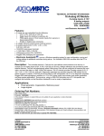
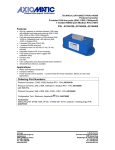
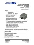
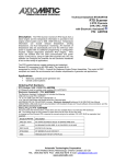
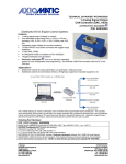
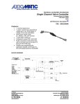
Preliminary
TECHNICAL DATASHEET #TDAX100050
DC MOTOR SPEED CONTROLLER
Speed Control
Drives a brushed DC motor up to 150A
1 Digital I/O
CAN SAE J1939, RS-232
High efficiency, Rugged
with Electronic Assistant®
P/N: AX100050
Features:
•
•
•
•
•
•
•
•
•
•
•
•
•
•
•
Unidirectional or bi-directional brushed DC motor control
Up to 150A output current to the motor
Highly efficient and robust design with isolation between drive
and processing circuits
Operation from 9 to 36VDC (24VDC nominal)
1digital input can be used as the control signal for a motor
enable, motor direction selected, or for the digital output.
The control input to drive the motor responds to CAN
messages.
4 configurable and independent ramps soften changes in
motor voltage and current.
A configurable E-stop shutdown (ramp) parameter is provided.
The 2A digital output can be used as a brake release or to drive an indicator lamp to show the motor
on/off state or to flag an error.
A +5V reference voltage is provided to power an external sensor or potentiometer.
CAN (SAE J1939) and RS-232 ports are provided.
Compact size for easy mounting on a vehicle
Corrosion resistant aluminum housing
Operational from -40 to 85°C (-40 to 185°F)
Electronic Assistant®
runs on a Windows operating system for user configuration of the motor
controller. An Axiomatic USB-CAN converter links the PC to the CAN bus.
Applications:
Mobile Equipment, Lift Equipment, Electric Vehicles for Material Handling
Ordering Part Numbers:
DC Motor Controller with CAN: AX100050
Accessories:
AX070105 Mating Plug Kit (DT06-12SA, W12S, 12 0462201-16141, 3 plugs)
AX070502 Configuration KIT includes the following.
USB-CAN Converter P/N: AX070501
1 ft. (0.3 m) USB Cable P/N: CBL-USB-AB-MM-1.5
12 in. (30 cm)CAN Cable with female DB-9 P/N: CABAX070501
AX070502IN CD P/N: CD-AX070502, includes: Electronic
Assistant® software; EA & USB-CAN User Manual
UMAX07050X; USB-CAN drivers & documentation; CAN
Assistant (Scope and Visual) software & documentation;
and the SDK Software Development Kit.
NOTE: To order this kit, you need only to specify P/N:
AX070502.
Figure 1 - User Configuration Using Electronic Assistant® (EA)
NOTES:
Network Termination: It is necessary to terminate the network with external termination resistors. The
resistors are 120 Ohm, 0.25W minimum, metal film or similar type. They are placed between CAN_H and
CAN_L terminals at both ends of the network.
Technical Specifications:
Input Specifications
Power Supply Input Nominal
Surge Protection
Under-voltage
Protection
Over-voltage
Protection
Isolation
Digital Input
Digital Input GND
TDAX100050
12 or 24VDC nominal; 9…36 VDC
Provided
Provided
Provided
All inputs are isolated from the power supply driving the motor and current outputs.
Active High (switched to +V)
Fully isolated with 5V threshold (Switch to Battery+)
The digital input can be used to enable/disable the motor, select the direction of the motor
and/or to control the digital output. Alternatively, the enable, direction, or DOUT control signals
can be taken from the J1939 network.
1 Digital GND connection is provided.
2
Block Diagram:
TDAX100050
3
Output Specifications
Output to Motor
H-bridge
150A @ 24VDC nominal for 2 minutes
100A @ 24VDC nominal for 5 minutes
50A @ 24VDC nominal for 1 hour
Overcurrent protection is provided.
Short circuit protection is provided @ +/- 250A (factory configurable).
1 on/off (2A)
The digital output can be used to drive a load (i.e. brake release) or an indicator lamp to show
when the motor is on or off, or to flag an error.
Digital Output
Digital Ground
Reference Voltage
Motor Direction
E-stop
When using CAN, the DOUT control message drives the digital output. By default, this
message is expected to be sent on the Proprietary A PGN (0xEF00). However, the user has full
configuration over the control message that the motor controller will respond to, so it can be
easily integrated into existing systems without requiring changes on the network.
1 Digital GND connection is provided.
+5V, 10 mA is available to power a sensor or potentiometer
Motor Direction is user configurable as Not Used, J1939 Message or mapped to Digital Input 1.
The Direction Method is configurable as Unidirectional, Bi-directional where forward is ON or Bidirectional in reverse.
Configurable E-stop shutdown (ramp) parameter
It determines the time it will take the motor controller to ramp from max. RPM (100% DC) to 0.
The same rate would be used in either direction.
If the control input goes into error mode (over-temperature shutdown, loss of communication,
etc.), or the CAN message disables the motor, the controller uses the E-stop (ramp) to shut off
the motor.
Inputs:
There are three ‘inputs’ that will affect how the motor responds, which are the control, enable
and direction inputs. The enable or direction input can be selected as either “Not Used”, “J1939
Message”, or “Digital Input 1”. When “J1939 Message” is selected, the corresponding received
CAN message setpoints take affect. By default, all these messages are expected to be sent on
the Proprietary A PGN (0xEF00). However, the user has full configuration over the control
messages that the motor controller will respond to, so it can be easily integrated into existing
systems without requiring changes on the network.
Motor Control Responses:
When “Duty Cycle Control” is selected the duty cycle applied to the motor will vary in proportion
to the received control input data.
In “Speed Control (open loop)”, the motor controller assumes that at 100% duty cycle, the motor
will be running at the maximum rated speed. The duty cycle applied to drive the motor will be
calculated based on this relationship. Both control methods are effectively similar.
Output Control Logic
For the “Enable Response”, the user can select the ‘input’ to either enable or disable the motor
when it is on. Additionally, when the motor output is to be overridden due to the enable input
state, there are three responses that can be selected. The motor can be shutoff (ramp to zero
using “Ramp Off” ramp) such as in an emergency stop situation, it can be ramped to the
minimum output (i.e. 0%) using the down ramp, or it can be ramped up to maximum output (i.e.
100%). The maximum output response is useful for situations where the load should be running
at full when in an error condition, i.e. if the m/c is driving a cooling fan.
For the “Direction Method”, refer to Motor Direction above.
Motor Speed:
The motor speed is always determined by a command message taken off of the J1939 bus.
The relationship between the motor command message and the motor speed is always linear,
as shown in the blue in Figure 2. However, the user can choose to set the output at the
minimum command to be higher than the output at the maximum command in order to get an
inverse profile as shown in the red line.
TDAX100050
4
RPM
Max. Speed
Minimum
Speed
0
Minimum
Command
Maximum
Command
Figure 2 – Motor Command vs. Speed Output Relationship
Ramps:
To limit the inrush current, the motor controller has independent, configurable up and down
ramps for both forward and reverse directions (1000 to 10,000 mSec). The ramp up setpoint
determines the time it takes the output to go from the lowest point on the curve above, to the
highest, in the corresponding direction. It is the opposite for the down ramps.
For more details refer to the user manual.
General Specifications
Microprocessor
Thermal Protection
Control Logic
Status Feedback
Fault Feedback
Diagnostics
RS-232 User
Interface
DSP56F8346
Thermal protection is built-in.
Standard embedded software is provided. Refer to the User Manual for details.
There are up to seven messages that give status feedback to the network: Motor Enable
Status, Motor Direction, Motor Duty Cycle, Motor Speed (RPM), Motor Current, Din1 State and
Dout1 State. By default, all these messages will be sent on the first Proprietary B PGN
(0xFF00), if the user selects a non-zero transmission rate. However, the user has full
configuration over the feedback messages so the motor controller can be easily integrated into
existing systems without requiring changes on the network.
Motor Open Circuit
Motor Over Current
Unit Over Temperature
Dout1 Fault
Each fault could be used to shutoff the motor, digital output or both. Each fault could also be
used to create a Diagnostic Trouble Code (DTC) and generate a DM1 on the J1939 network.
Configurable
By default, none of the faults that can be detected will generate Diagnostic Messages on the
J1939 network. If the setpoint is set to “TRUE”, the user can select the SPN that will be used to
generate the Diagnostic Trouble Code (DTC). There is also a setpoint that will allow the user to
implement a delay before sending a DM1 message. Diagnostic data is stored in a non-volatile
log to support requests for DM2. Each entry in the log is a record of the SPN, FMI and OC for
the fault that has occurred. Refer to the user manual for details.
Used for diagnostic purposes only
Electronic Assistant® (royalty-free license for use)
CAN User Interface
TDAX100050
P/N: AX070502, the Axiomatic Configuration KIT includes the following.
USB-CAN Converter P/N: AX070501
1 ft. (0.3 m) USB Cable P/N: CBL-USB-AB-MM-1.5
12 in. (30 cm)CAN Cable with female DB-9 P/N: CAB-AX070501
AX070502IN CD P/N: CD-AX070502, includes: Electronic Assistant® software; EA & USBCAN User Manual UMAX07050X; USB-CAN drivers & documentation; CAN Assistant (Scope
and Visual) software & documentation; and the SDK Software Development Kit. Refer to
Figure 1.
5
1 CAN port (SAE J1939)
The software was designed to provide flexibility and provides the following.
•
Configurable ECU Instance in the NAME (for multiple ECU’s on the network)
•
Configurable Motor Control Logic
•
Configurable Digital Output Logic
•
Configurable Transmit Messaging Parameters
•
Configurable Receive Messaging Parameters
•
Configurable Diagnostic Messaging Parameters, as required
•
Diagnostic Log, maintained in non-volatile memory
Setpoints are accessed using standard Memory Access Protocol (MAP) with proprietary
addresses. The Electronic Assistant® allows for quick and easy configuration of the unit over
the CAN network.
The motor controller is compliant with Bosch CAN protocol specification, Rev.2.0, Part B, and
the following J1939 standards.
Table 1: J1939 Compliance
OSI Network
Model Layer
J1939 Standard
Physical
J1939/11 – Physical Layer, 250K bit/s, Twisted Shielded Pair.
J1939/15 - Reduced Physical Layer, 250K bits/sec, Un-Shielded Twisted Pair
(UTP).
J1939/21 – Data Link Layer
CAN Interface
Data Link
Request (PGN 59904)
Acknowledgement (PGN 59392)
Transport Protocol – Connection Management (PGN 60416)
Transport Protocol – Data Transfer Message (PGN 60160)
Proprietary A (Default Control Message) (PGN 61184)
Proprietary B (Default Feedback Message) (PGN 65280)
Proprietary B, available messages (PGN’s 65281 to 65535)
J1939/81 – Network Management
J1939, Appendix B – Address and Identity Assignments
Network Layer
Arbitrary Address Capable ECU - It can dynamically change its network
address in real time.
The controller supports: Address Claimed Messages (PGN 60928) and
Commanded Address Messages (PGN 65240).
J1939/71 – Vehicle Application Layer
Application Layer
Software Identification (PGN 65242)
None of the application layer PGN’s are supported as part of the default
configuration. However, the controller could be configured such that any of
the transmitted messages to be sent will use a PGN from this section, or for
any of the received messages to recognize a PGN from this section.
It is the user’s responsibility to configure the controller such that it will not
violate the J1939 standard.
J1939/73 – Application Layer – Diagnostics
DM1- Active Diagnostic Trouble Codes (PGN 65226)
DM2 – Previously Active Diagnostic Trouble Codes (PGN 65227)
DM3 – Diagnostic Data Clear/Reset for Previously Active DTC’s (PGN 65228)
DM14 – Memory Access Request (PGN 55552)
DM15 – Memory Access Response (PGN 55296)
DM16 – Binary Data Transfer (PGN 55040)
TDAX100050
6
Electrical Connections
Mounting
Packaging and Dimensions
Weight
Operating Conditions
Protection Rating
Regulatory Approvals
Refer to Table 2.
Wires should be of the appropriate gauge to meet requirements of applicable
electrical codes and suit the specifications of the connector(s).
The controller has 4 mounting holes 0.281 H x 0.625 W inches (7.14 x 15.88 mm).
The holes are sized for ¼ inch or M6 bolts. The bolt length will be determined by
the end-user's mounting plate thickness. Typically 20 mm (3/4 inch) is adequate.
A grounding stud is also provided. Ground the chassis for safety purposes and
proper EMI shielding. Make this connection using one of the mounting bolts holding
the controller to the machine.
Aluminum extrusion with stainless steel end plates
8.50 x 12.22 x 3.82 inches (W X L X H including connectors)
215.9 x 310.3 x 97.2 mm
Refer to Figure 3.0.
11.95 lbs. (5.42 kg)
Operating: -40 to 85°C (-40 to 185°F)
IP64
The motor controller is not CE marked, as it is not a self-contained system.
Table 2 - Electrical Pin Out Chart
CAN and I/O Connector:
12 pin Deutsch P/N: DT04-12PA-LE10
Mating Connector: AX070105 Mating Plug Kit
CAN and I/O Connector
Pin #
Description
1
CAN_HI
2
CAN_LO
3
Digital Input 1
4
DIN1 +Vref
5
Digital Output 1
6
DOUT1 GND
7
RS-232 Transmit
8
RS-232 Receive
9
RS-232 GND
10
Not Used, Plug
11
Not Used, Plug
12
Not Used, Plug
Power and Motor Control:
Threaded Copper Rods – 5/16-18 inches
Refer to drawing for orientation of rods.
Battery +
Motor –
Battery Motor +
TDAX100050
7
Figure 3 - Dimensional Drawing
Specifications are indicative and subject to change. Actual performance will vary depending on the application and
operating conditions. Users should satisfy themselves that the product is suitable for use in the intended application.
All our products carry a limited warranty against defects in material and workmanship. Please refer to our Warranty,
Application Approvals/Limitations and Return Materials Process as described on www.axiomatic.com/service.html.
Form: TDAX100050-07/14/09
TDAX100050
8