1
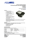
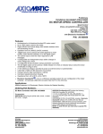
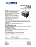
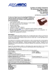
TECHNICAL DATASHEET #TDAX021600 Single Channel Valve Controller Universal Input, 2A Output CAN (SAE J1939) Inline with Electronic Assistant® P/N: AX021600K Features: 1 universal signal input 1 output: current 0-2 A; proportional voltage up to Vps; PWM signal; or voltage 0-Vps (user selectable) Wide power supply range (8…60VDC), 12V, 24V nominal 1 CAN (SAE J1939) port CANopen® module P/N: AX021602 PCB is enclosed in heat shrink wrap with 6 inch lead wires terminated in 3 Deutsch IPD DT06 plugs. Flexible user programming for application-specific control logic via the CAN based Electronic Assistant®. BLOCK DIAGRAM Ordering Part Numbers: SAE J1939 Controller KIT: AX021600K Or you can order the items separately. Controller (Shrink wrapped with lead wires/connectors): AX021600 Accessories: AX070106 4-socket Mating Plug Kit AX070107 2-socket Mating Plug Kit AX070104 3-socket Mating Plug Kit Electronic Assistant®: AX070502 Technical Specifications: Inputs Power Supply Input - Nominal Protection CAN Universal Signal Input 12V, 24V or 48VDC nominal (8…60 VDC power supply range) Reverse polarity protection is provided. Overvoltage protection up to 65V is provided. Overvoltage (undervoltage) shutdown of the output load is provided. SAE J1939 Commands Refer to Table 1.0 All inputs are user selectable. Table 1.0 – Input – User Selectable Options Analog Input Functions Voltage Input, Current Input or Resistive Input Voltage Input 0-1V (Impedance 1 MOhm) 0-2.5V (Impedance 1 MOhm) 0-5V (Impedance 200 KOhm) 0-10V (Impedance 133 KOhm for 0-5V, 133 to 20 KOhm for 5-10V) Current Input 0-20 mA (Impedance 124 Ohm) 4-20 mA (Impedance 124 Ohm) Resistive Input 25Ω to 250 kΩ Digital Input Functions Digital Input Input Impedance Discrete Input, PWM Input, Frequency Input 5V CMOS 0 to 100% 10 Hz to 1kHz 100 Hz to 10 kHz 10 Hz to 1kHz 100 Hz to 10 kHz Active High, Active Low 1 MOhm High impedance, 10KOhm pull down, 10KOhm pull up to +5V Input Accuracy Input Resolution < 1% 12-bit Digital Input Level PWM Input Frequency Input Outputs CAN Output Output Accuracy SAE J1939 Messages Up to 2A High Side Switch, Current Sensing, Grounded Load The user can select the following options for output using the EA. Output Disable Discrete Output (0-Vps) Output Current (PID loop*, with current sensing) (0-2A) Proportional Output Voltage (up to Vps) Output PWM Duty Cycle (0-100% D.C.) *Parameters are password protected. Refer to the user manual for details. Output Current mode <2% Output Voltage mode <3% Output PWM Duty Cycle mode <3% General Specifications Microprocessor Control Logic Communications User Interface TDAX02160X 32-bit, 128 KByte program memory User programmable functionality using Electronic Assistant® Refer to the user manual for details. 1 CAN port (SAE J1939), CANopen® is available in Model AX021602. Electronic Assistant® for Windows operating systems comes with a royalty-free license for use. The Electronic Assistant® requires an USB-CAN converter to link the device’s CAN port to a Windows-based PC. An Axiomatic USB-CAN Converter AX070501 is available as part of the Axiomatic Configuration KIT, ordering P/N: AX070502. 2 Network Termination Operating Conditions Packaging Protection Weight Electrical Connections It is necessary to terminate the network with external termination resistors. The resistors are 120 Ohm, 0.25W minimum, metal film or similar type. They should be placed between CAN_H and CAN_L terminals at both ends of the network. -40 to 85 C (-40 to 185 F) PCB assembly (conformal coated PCB in heat shrink wrap) with 6 inch (153 mm) 18 WG lead wires terminated with 3 Deutsch IPD DT06 plugs made of thermoplastic with silicone seals and using #16 sized nickel contacts. 1.52 x 17.76 x 0.66 inches or 38.6 x 451.1 x 16.7 mm (W x L x H excluding mating connectors) IP50 (PCB conformal coated and housed in heat shrink wrap) NOTE: Deutsch IPD connectors are rated for submersion (3 ft., 0.9 m). 0.20 lbs. (0.09 kg) CAN Connector: 3 pin Deutsch IPD P/N: DT04-3P A: CAN_H (Yellow) B: CAN_L (Green) C: CAN Shield (Grey) Mates with P/N: DT06-3S including W3S wedgelock and sockets. A mating plug kit is available from Axiomatic. Use ordering P/N: AX070104. (The mating plug kit is comprised of Deutsch IPD P/N: DT06-3S, W3S and 3 contact sockets 0462-201-16141.) Power and Output Connector: 4 pin Deutsch IPD P/N: DT04-4P 1: Power Input (Red) 2: Power GND (Black) 3: Signal Output + (White/Red) 4: Signal Output – (Internally connected to Power GND) (Brown) Mates with P/N: DT06-4S including W4S wedgelock and sockets. A mating plug kit is available from Axiomatic. Use ordering P/N: AX070106. (The mating plug kit is comprised of Deutsch IPD P/N: DT06-4S, W4S and 4 contact sockets 0462-201-16141.) Signal Input Connector: 2 pin Deutsch IPD P/N: DT04-2P 1: Signal Input (Blue) 2: Signal GND (Black) Mates with P/N: DT06-2S including W2S wedgelock and sockets. A mating plug kit is available from Axiomatic. Use ordering P/N: AX070107. (The mating plug kit is comprised of Deutsch IPD P/N: DT06-2S, W2S and 2 contact sockets 0462-201-16141.) TDAX02160X 3 The network part of the controller is compliant with Bosch CAN protocol specification, Rev.2.0, Part B, and the following J1939 standards. ISO/OSI Network Model Layer J1939 Standard Physical J1939/11 – Physical Layer, 250K bit/s, Twisted Shielded Pair. Rev. SEP 2006. J1939/15 - Reduced Physical Layer, 250K bits/sec, Un-Shielded Twisted Pair (UTP). Rev. AUG 2008. J1939/21 – Data Link Layer. Rev. DEC 2006 The controller supports Transport Protocol for Commanded Address messages (PGN 65240) and software identification -SOFT messages (PGN 65242). It also supports responses on PGN Requests (PGN 59904). J1939, Appendix B – Address and Identity Assignments. Rev. FEB 2010. J1939/81 – Network Management. Rev. 2003-05. The controller is an Arbitrary Address Capable ECU. It can dynamically change its network address in real time to resolve an address conflict with other ECUs. The controller supports: Address Claimed Messages (PGN 60928), Requests for Address Claimed Messages (PGN 59904) and Commanded Address Messages (PGN 65240). N/A in J1939. N/A in J1939. N/A in J1939. J1939/71 – Vehicle Application Layer. Rev. FEB 2010 The controller can receive application specific PGNs with input signals and transmit application specific PGNs with up to five output signals. All application specific PGNs are user programmable. J1939/73 – Application Layer – Diagnostics. Rev. FEB 2010 Memory access protocol (MAP) support: DM14, DM15, DM16 messages used by EA to program setpoints. Data Link Network Transport Session Presentation Application Control Logic The controller consists of a set of internal functional blocks, which can be individually programmed and arbitrarily connected together to achieve the required system functionality, Fig. 1. For additional flexibility, in a majority of functional blocks, logical input signals can be inverted. Each functional block is absolutely independent and has its own set of parameters, or setpoints, used to control its functionality. The setpoints are accessible through CAN using Axiomatic Electronic Assistant® (EA) software. There are two types of the controller functional blocks. One type represents the controller hardware resources, for example: universal input or PWM output. The other type is purely logical – these functional blocks are included to program the user defined functionality of the controller. The user can build virtually any type of a custom control by logically connecting inputs and outputs of the functional blocks. This approach gives the user an absolute freedom of customization and an ability to fully utilize the controller hardware resources in a user’s application. TDAX02160X 4 Voltage, Current, Resistance, Frequency, PWM, Discrete Level Universal Input Control Input Conversion Function PWM Output Load: Valve Coil Disable Input Current Sensor Global Parameters CAN Output Message CAN Input Signal The default controller configuration can be different from the one shown here. J1939 CAN Bus Logical Input Logical Output As an example, Universal Input is connected to the Conversion Function and the Conversion Function to the PWM Output, providing a path for the signal from input to output through the Conversion Function. CAN Input Signal and CAN Output Message functional blocks are not used in this example. Figure 1. The Controller Internal Structure Note: CANopen® is a registered community trade mark of CAN in Automation e.V. Specifications are indicative and subject to change. Actual performance will vary depending on the application and operating conditions. Users should satisfy themselves that the product is suitable for use in the intended application. All our products carry a limited warranty against defects in material and workmanship. Please refer to our Warranty, Application Approvals/Limitations and Return Materials Process as described on www.axiomatic.com/service.html. Form: TDAX021600-09/30/14 TDAX02160X 5