1
TECHNICAL DATASHEET #TDAX021200
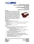
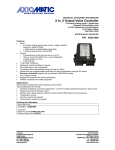
CAN to 9 Output Valve Controller
P/N: AX021200
12V, 24V, 48V, 72V
CAN (SAE J1939)
with Electronic Assistant®
Features:
• Command messages are received through the CAN network
(no physical inputs)
• 9 outputs are user selectable from the following (up to a
maximum of 7A of controller power supply intake at one
time).
o Output Disabled
o Proportional Current
o Hotshot Digital
o On/Off Digital
o Proportional Voltage
o PWM Duty Cycle
• 12V, 24V, 42V, 48V or 72VDC nominal input power
• 1 CAN port (SAE J1939), 1 RS-232 port
• CANopen® module available on request (P/N: AX021201)
• Hardware is also available as a platform for application-specific software
runs on a Windows operating system for user configuration. An
• Electronic Assistant®
Axiomatic USB-CAN converter links the PC to the CAN bus.
• Rugged IP67 packaging and connectors
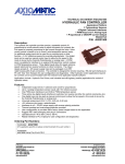
Description:
The controller features 1 CAN port for controlling the outputs and diagnostics over the CAN bus. It accepts a
wide variety of nominal input power supply voltages (12V, 24V, 42V, 48V or 72VDC). Using the CAN
network, it can provide control of up to nine outputs, configured for a wide variety of responses. For
example, it can drive proportional valves, on/off valves or provide a hotshot control profile. PWM signal or
proportional voltage outputs are also user selectable. Standard software is provided. The sophisticated
microprocessor can accommodate complex application-specific control algorithms for advanced machine
control on request. Rugged IP67 rated packaging in addition to the wide-ranging power supply input section
suits the harsh environment of mobile equipment with on-board battery power. Settings are user
configurable via a Windows-based Electronic Assistant® configuration tool interfacing to the controller via an
USB-CAN device.
Applications:
•
•
•
Off-highway construction equipment
Municipal vehicles
Material handling equipment (forklifts, etc.)
Ordering Part Numbers:
SAE J1939 version
CANopen® version
Controller: AX021200
Controller: AX021201
EDS File: EDS-AX021201
Contact Axiomatic for a quotation to provide application-specific
control logic.
Accessories:
PL-DTM06-12SA-12SB Mating Plug Kit (no DB-9)
(The KIT is comprised of: DTM06-12S, DTM06-12SB, 2 W12S and 24 contacts.
The Axiomatic stock # is FG-IOCTRL-19.)
AX070502 Configuration KIT includes the following.
PC-based CANopen Configuration Tool:
USB-CAN Converter P/N: AX070501
Industry standard CANopen PC-based software
1 ft. (0.3 m) USB Cable P/N: CBL-USB-AB-MM-1.5
12 in. (30 cm)CAN Cable with female DB-9 P/N: CAB-AX070501
AX070502IN CD P/N: CD-AX070502, includes: Electronic
Assistant AX070500 software; EA & USB-CAN User Manual
UMAX07050X; USB-CAN drivers & documentation; CAN Assistant
(Scope and Visual) software & documentation; and the SDK
Software Development Kit.
NOTE: To order this kit, you need only to specify P/N:
AX070502.
Block Diagram:
TDAX021200
2
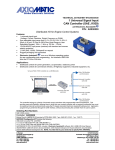
Set up of AX021200 Controller on a CAN Network:
Technical Specifications:
Input Power Supply Specifications
Power Supply Input - Nominal
12V, 24V, 42V, 48V or 72V DC nominal
Maximum 80 VDC power supply (8…80VDC)
Surge protection is provided.
NB. The maximum total current draw permitted on the power supply input pins is 7
Amps @ 24VDC, at one time.
Reverse Polarity Protection
Provided
Input Impedance
400 KOhms
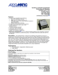
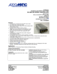
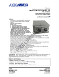
Supply Intake Current vs Total Output Current [A]
16.0
14.0
12.0
10.0
8.0
6.0
4.0
2.0
0.0
0.58
1.06
1.54
2.02
2.61
3.19
3.78
4.47
5.16
5.85
S uppl y I nt a k e C ur r e nt [ A ]
TDAX021200
3
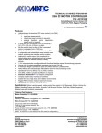
Supply Voltage vs Intake Current when all outputs ON at 1500 mA
5.00
4.50
4.00
Intake Current [Amps]
3.50
3.00
2.50
2.00
1.50
1.00
0.50
0.00
24
32
48
65
80
Supply Voltage [V]
WARNING: The 9 outputs are user selectable from 0 to 2000 mA but the unit can only handle a maximum
of 7A of controller power supply intake at one time. At no time should the total intake current of the controller
exceed 7A due to the rating of the connector. Failure to do so will result in unpredictable damage to unit.
Input Specifications
CAN commands
(no physical inputs available)
SAE J1939 {CANopen® (model AX020201)}
There are eleven setpoints per channel that are associated with the J1939
command message that is received by the controller from the network bus.
Refer to the user manual for details.
Output Specifications
Proportional Outputs
High side (sourcing)
9 outputs, 12 or 24V
Each output is configurable up to 2A.
The number of outputs ON at one time is limited by the rating of the Deutsch IPD
contacts (pins on the connector).
NB. The maximum total current draw permitted on the power supply input pins is 7
Amps @ 24VDC, at one time.
Output Type
The user can select between the following outputs. Refer to Table 1.0.
Output Disabled
Proportional Current (0…2A)
Hotshot Digital (0…2A, 0…10000 mSec.)
On/Off Digital (0…2A)
Proportional Voltage (0…85V)
PWM Duty Cycle (150Hz…5000Hz, 0 to 100%)
Output Adjustments
Digital Current: 0 to 2000 mA
Hotshot Hold Time: 0 to 10000 ms
Proportional Current: 0 to 2000 mA
Proportional Voltage: 0 to 85V
PWM Duty Cycle: 0 to 100%
PWM Frequency: 150 Hz to 5000 Hz
Ramp Up: 0 to 10000 ms
Ramp Down: 0 to 10000 ms
Dither Frequency: 50 to 400 Hz
Dither Amplitude: 0 to 500 mA
For default settings, refer to the user manual.
TDAX021200
4
Control Logic
By default, any output on the controller uses a Proprietary B message to receive
command messages to control the output, and to send feedback data to the
network bus.
There are twelve setpoints per channel that are associated with the output and how
it responds.
There are five setpoints per channel that are associated with the J1939 feedback
message that can be sent by the ECU to the network bus.
Refer to the user manual for details.
Current Feedback
The current feedback is sampled every 10ms. The repetition rate is user selectable
as well as the type of filter that is applied to the measured data, before it is used in
the PID control loop and/or sent to the bus. The available filters are:
•
Filter Type 0 = No Filter
•
Filter Type 1 = Moving Average
•
Filter Type 2 = Repeating Average
Protection
Overcurrent protection is provided.
Short circuit protection is provided.
NB. Outputs are separately protected against short circuits to both power and
GND. If the current at the output exceeds 6A, the protection circuitry will shut off
the output signal, regardless of what type of output mode had been selected for
that channel.
Error Detection
The controller can detect and flag overcurrent and open circuit loads, which can be
read via the J1939 network for diagnostic purposes.
Output Impedance
18-19 KOhms
Table 1.0 Output Types for AX021200
Type
Description
Output Disabled
The output channel is disabled, and will not respond to any messages from the bus. None of
the other output setpoints apply.
Proportional Current
The controller regulates the current through a solenoid to precisely control the response of a
proportional valve. The unit measures the current feedback, and uses it in a high-speed P-I-D
loop to accurately set the current through the load. A high frequency signal (20kHz) is used to
provide an output with low ripple. If required, a low frequency signal can be superimposed on
the output to dither the load with adjustable frequency and amplitude.
The output current will vary linearly with respect to the command signal received from the bus,
with up to two slopes. Refer to Figure 1.0.
Minimum, Breakpoint and Maximum currents can be set anywhere from 0mA to 2000mA. If a
single slope is required, set the Breakpoint Output and Command setpoints equal to the
Minimum setpoints. If an inverse response profile is required, simply set the Minimum Output
higher than the Maximum Output. Command setpoints are limited by each other, in that the
Minimum <= Breakpoint <= Maximum, so they will have to be adjusted in order.
A feedback signal sent to the network will be sent as a WORD with a 1mA/bit resolution, and
0mA offset. The data in the message will be the current through the load, as measured by the
controller.
For error detection, if the absolute difference between the measured current and the target
current is greater than or equal to 200mA, the controller will flag an error at the output. If the
measured value is higher than the target, the controller flags an overcurrent; otherwise, it flags
an open circuit at the load. These thresholds are not user configurable.
Accuracy: +/-1% over the 2000 mA range
Hotshot Digital
In this mode, the output can be hotshot with a current to turn the load on, and then dropped to
a holding current to keep the load on with less energy. For digital loads that have a high duty
cycle, using this type of output can help improve the overall system efficiency. The current at
which the output is hotshot, and the length of time it is held at this value, are both configurable
setpoints, as is the holding current. Refer to Figure 2.0.
In this mode, a command message less than or equal to the Off Threshold setpoint will turn
the output off. A message greater than or equal to the On Threshold will turn the output on.
Command message values between these two setpoints will have no affect on the state of the
output.
Dither, Breakpoint and Ramp setpoints do not apply in this mode. Feedback messages and
error detection properties are the same as for proportional current outputs.
Accuracy: +/-1% over the 2000 mA range
TDAX021200
5
On/Off Digital
In this mode, the output will either be off, or switched to the power supply voltage. The output
will respond to changes in the command message the same way as for a hotshot digital
response.
A feedback signal sent to the network will be sent as a WORD with a 1mA/bit resolution, and
0mA offset. The data in the message will be the current through the load, as measured by the
controller.
For error detection, if the measured current at the load is less then 100mA, an open circuit will
be flagged. If the current at the load is greater than or equal to 2500mA, an overcurrent will be
flagged. These thresholds are not user configurable.
Proportional Voltage
The controller will adjust the duty cycle of the output PWM signal such that the average
voltage from the pin will be the target voltage. The unit measures the power supply voltage,
and uses it to calculate the required duty cycle of the output signal. Typically, a high frequency
signal (20kHz) is used to provide an output that will have low ripple after filtering. External
filtering will be required to turn this signal into a voltage output.
Refer to Figure 1.0. The relationships between the Output setpoints and the Command
setpoints are the same as with a current output. Up and down ramps would also apply in the
same manner as with a current output. The Minimum, Breakpoint and Maximum voltages can
be set anywhere from 0V to 85V.
In this mode, a feedback signal sent to the network will be sent as a WORD with a 0.01V/bit
resolution, and 0V offset. The data in the message will be the target output voltage, as
calculated based on the response profile variables.
For error detection, if the measured current at the load is less then 100mA, an open circuit will
be flagged. If the current at the load is greater than or equal to 2500mA, an overcurrent will be
flagged. These thresholds are not user configurable.
Accuracy: +/-5% average of the actual output voltage with respect to the target commanded
voltage.
PWM Duty Cycle
In this mode, the controller will adjust the duty cycle of the output PWM signal. Refer to Figure
1.0.
The relationships between the Output setpoints and the Command setpoints are the same as
with a current output. Up and down ramps would also apply in the same manner as with a
current output. The Minimum, Breakpoint and Maximum duty cycles can be set anywhere from
0% to 100%.
Any output configured for a duty cycle response will have a setpoint available that will allow
the user to adjust the frequency of the output signal. However, there are several restrictions
for this parameter as listed below.
a.
Certain channels always have the same frequency for the output signal. This means that
if any one of these channels is configured for a current output (proportional or hotshot),
the PWM Frequency setpoint will be ignored, and the output frequency will always be
20kHz. The output channels that share a frequency are channels 1 to 6, and channels 7
to 9 respectively. If both current and PWM output types are required, they will have to be
split between those two groups in order for the controller to perform as expected.
b.
If condition (a) has been met (no current output in that group of channels), then the
frequency that will be used for the group will be of the output channel with the LOWEST
index number that has been configured as a PWM duty cycle output, and has a non-zero
entry in this setpoint. This parameter will be ignored for all the other channels.
c.
The new PWM frequency will NOT take effect until the unit has been reset by cycling the
power.
In this mode, a feedback signal sent to the network will be sent as a WORD with a 0.01
%dc/bit resolution, and 0%dc offset. The data in the message will be the target output duty
cycle, as calculated based on the response profile variables.
For error detection, if the measured current at the load is less then 100mA, an open circuit will
be flagged. If the current at the load is greater than or equal to 2500mA, an overcurrent will be
flagged. These thresholds are not user configurable.
Accuracy: +/- 1.15% average
TDAX021200
6
Output Response Profiles:
OUTPUT
Maximum
Single Slope
Dual Slope
Either
Breakpoint
Minimum
COMMAND
0
Minimum
Breakpoint
Maximum
Figure 1 – Proportional Output vs. Command Profile
ON
COMMAND
OFF
Hotshot
Current [mA]
OUTPUT
Hold
Current [mA]
0 [mA]
Hotshot Time [ms]
TIME
Figure 2 –Hotshot Digital Profile
General Specifications
Microprocessor
DSP56F8346
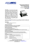
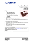
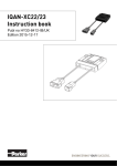
Efficiency
85.5%@24V, 89.2% over entire voltage range
Refer to Figure 3.0.
Control Logic
Standard embedded software. Refer to the user manual for details.
Application-specific software is available on request.
Communications
1 CAN port (2.0B, SAE J1939)
CANopen® (model AX021201) and other CAN based protocols available on request
1 RS-232 port
User Interface
User configuration and diagnostics are provided with the Axiomatic
Electronic Assistant®. The Axiomatic Service Tool is a
Windows-based graphical user interface that allows easy configuration of the
controller setpoints. Refer to Table 3.0 for details.
Network Termination
It is necessary to terminate the network with external termination resistors. The
resistors are 120 Ohm, 0.25W minimum, metal film or similar type. They should
be placed between CAN_H and CAN_L terminals at both ends of the network.
TDAX021200
7
Input vs Output Pow er vs Efficiency
140.000
120.000
100.000
80.000
60.000
40.000
20.000
0.000
1
2
3
4
5
6
7
8
9
N um be r of Ou t pu t s ON
Supply Input Power
[ W]
Tot al Out put Power
[ W]
Ef f iciency
[ %]
Input vs Output Pow er and Efficiency over 20-80V range
140
120
100
80
60
40
20
0
20.07
24.011
32.084
48.091
65.051
72.055
80.005
S up p l y Vol t a g e [ V]
Input Power
Out put Power
Ef f iciency
Figure 3.0 – Efficiencies
TDAX021200
8
CAN Interface
1 CAN port (SAE J1939)
The software was designed to provide flexibility and provides the following.
•
Configurable ECU Instance in the NAME (for multiple ECU’s on the network)
•
Configurable Input Parameters
•
Configurable Output Parameters
•
Configurable PGN and Data Parameters
•
Configurable Diagnostic Messaging Parameters, as required
•
Diagnostic Log, maintained in non-volatile memory
Note: Configurable parameters are also called setpoints.
There are ten setpoints per channel that are associated with the J1939 command
message that is received by the ECU from the network bus. There are setpoints
used with both output and fault channels. To use J1939, refer to the user manual.
The Axiomatic AX021200 is compliant with Bosch CAN protocol specification,
Rev.2.0, Part B, and the following J1939 standards.
Table 2: J1939 Compliance
OSI Network Model
Layer
J1939 Standard
Physical
J1939/11 – Physical Layer, 250K bit/s, Twisted Shielded Pair.
J1939/15 - Reduced Physical Layer, 250K bits/sec, UnShielded Twisted Pair (UTP).
J1939/21 – Data Link Layer
Data Link
The controller supports Transport Protocol for Diagnostic DM1
and DM2 messages (PGN 65226 and 65227). It supports
responses on PGN Requests (PGN 59904) and
acknowledgements (PGN 59392). It also supports Proprietary B
messaging (PGN 65280 to 65535), and uses a proprietary
scheme described in the User Manual.
J1939/81 – Network Management
J1939, Appendix B – Address and Identity Assignments
Network Layer
Arbitrary Address Capable ECU - It can dynamically change its
network address in real time.
The controller supports: Address Claimed Messages (PGN
60928), Requests for Address Claimed Messages (PGN
59904) and Commanded Address Messages (PGN 65240).
J1939/71 – Vehicle Application Layer
None of the application layer PGN’s are supported as part of
the default configurations. However, the controller could be
configured such that any of the input messages to be sent will
use a PGN from this section, or for the outputs to respond to
the data in a message with a PGN from this section.
The data size, index, resolution and offset can all be configured
for the appropriate SPN associated with the PGN.
It is the user’s responsibility to configure the controller such that
it will not violate the J1939 standard.
Application Layer
J1939/73 – Application Layer – Diagnostics
The controller can be configured to send “Active Diagnostic
Trouble Code” DM1 messages (PGN 65226) for any I/O
channel. Warning and Protect diagnostics will automatically
become previously active when cleared. “Previously Active
Diagnostic Trouble Codes” DM2 messages (PGN 65227) are
available on request. Shutdown diagnostics will be cleared
upon receiving a “Diagnostic Data Clear/Reset for Active
DTC’s” DM11 message (PGN 65235). Occurrence counts in
the diagnostic log will be cleared upon receiving a “Diagnostic
Data Clear/Reset for Previously Active DTC’s” DM3 message
(PGN 65228).
Diagnostics – CAN Network
TDAX021200
Each output channel can be configured to send diagnostic messages to the
network if the load goes out of range. There are four setpoints per output
channel, and ten per fault channel, that are associated with if and how diagnostic
messages will be sent to the network bus. Alternatively, if the Axiomatic
Proprietary B scheme is used, the status byte of the feedback message could be
used to recognize an error at the output. How the controller detects a fault for a
channel will depend on the output type. In addition to the output channels, three
other types of fault channels can be reported to the network using diagnostic
messaging. They are Over Temperature (of the processor), Over Voltage and
Under Voltage (of the power supply). Refer to the user manual for details.
9
RS-232
The RS-232 interface can be used to changes some setpoints during set up.
It also provides the tools for troubleshooting and debugging the controller.
For example, how much current is being sourced from an output is available from
this port as is the microprocessor’s temperature. It can also be used to verify that
the CAN commands are truly assigning an output as ON or OFF.
For more detailed information please refer to the User Manual.
Table 3.0 - AX070500 Electronic Assistant
Electronic Assistant®
The Electronic Assistant (EA) runs on any
modern PC with the Microsoft Windows®
2000 operating system or higher. It comes
with a royalty-free license for use.
System Requirements:
Operating System: Windows 2000 or
higher including 64-bit editions
Port: USB 1.1 or 2.0 full speed
Display: VGA (XGA or better with 1024 x
768 recommended)
Setup and Configuration:
Refer to the User Manual UMAX07050X.
To order the EA software at the time of
initial purchase, order the KIT AX070502
(see above) which includes the
Axiomatic USB-CAN converter. For
additional EA and USB-CAN software
ONLY CD’s, use ordering P/N: CDAX070502.
Figure 4.0 Configuration screen from the Electronic Assistant
The Electronic Assistant® (EA) is a software configuration tool that runs on a PC
connected to a J1939 bus via a USB to CAN converter, AX070501. Upon being
connected to the bus, the EA will find all the Electronic Control Units (ECU) on the
bus, and recognized those manufactured by Axiomatic. Using this tool, a user can
quickly configure an Axiomatic ECU for the desired performance over a wide variety
of applications.
Electrical Connections
Deutsch DTM series 24 pin receptacle (DTM13-12PA-12PB-R008)
Mating plug: Deutsch DTM06-12SA and DTM06-12SB
with 2 wedgelocks (WM12S) and 24 contacts (0462-201-20141).
20 AWG wire is recommended for use with contacts 0462-201-20141.
Use dielectric grease on the pins when installing the controller.
Refer to Table 4.0 for the pin out.
TDAX021200
10
Packaging and Dimensions
High Temperature Nylon housing - Deutsch IPD PCB Enclosure (EEC-325X4B)
4.62 x 5.24 x 1.43 inches 117.42 x 133.09 x 36.36 mm
(W x L x H excluding mating plugs)
Operating Conditions
-40 to 70°C (-40 to 158°F) with all 9 outputs ON at 1.5A
-40 to 85°C (-40 to 185°F) with less than 9 outputs ON at 1.5A
Weight
0.60 lbs. (0.27 kg)
Protection
IP67, Unit is conformally coated in the housing. Plugs carry an IP69 rating.
Table 4.0 – Pin out: AX021200
Grey Connector
Pin #
1
2
3
4
5
6
7
8
9
10
11
12
Function
Ground 5
Ground 4
Ground 3
Ground 2
Ground 1
BATT BATT +
Output 1
Output 2
Output 3
Output 4
Output 5
Black Connector
Pin #
1
2
3
4
5
6
7
8
9
10
11
12
Function
Output 6
Output 7
Output 8
Output 9
RS232 TXD (Not Used)
CAN HI
CAN LO
RS232 RXD (Not Used)
Ground 9
Ground 8
Ground 7
Ground 6
Note: CANopen® is a registered community trade mark of CAN in Automation e.V.
Specifications are indicative and subject to change. Actual performance will vary depending on the application and
operating conditions. Users should satisfy themselves that the product is suitable for use in the intended application. All
our products carry a limited warranty against defects in material and workmanship. Please refer to our Warranty,
Application Approvals/Limitations and Return Materials Process as described on www.axiomatic.com/service.html.
Form: TDAX021200- 07/20/09
TDAX021200
11