1
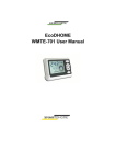
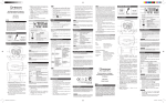
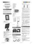
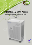
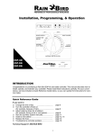
User Manual
Many thanks for your selection of our products
and services, and also for your trust
and support to us.
-1-
Instruction Manual
for WH611WW/RF/MRF; WH612WW/RF; WH614WW/RF Thermostat
Features:
1. Heating / Cooling control;
2. Programmable function of 24 time
sections per day and 7-day per week;
3. 3 sets of permanent programs (2 sets of
factory setting program and 1 set of selfsetting program);
4. Pre-cooling or pre-heating function in automatic program;
5. Backlight display (at 220V);
6. The temperature difference adjustable between off and on;
7. Allowable to calibrate the temperature display;
8. Allowable to connect the external temperature sensor. Outdoor temperature
display provided(WH611WW/WH612WW/WH614WW);
9. Display adjustable between room temperature, outdoor temperature and preset
temperature;
10. Fan speed adjustable automatically or manually to control of no fan(WH611 WW/RF),
single-speed fan(WH612WW/RF) or three-speed fan (WH614WW/RF);
11. Display adjustable between ℃ and ℉;
12. Allowable to keep user settings after power shutdown;
13. Antifreeze (or energy-saving) when turn off;
14. Allowable to set the highest temperature of heating and the lowest temperature
of cooling.
-2-
15. Three transmission modes for selection, i.e. wired, wireless or multi-channel
transmission.
16. Multiple fault detection and display functions.
17. Energy-consumption display function
18. Allowed for wired / wireless installation in standard box (WH611 WW, WH612WW,
WH614WW), or allowed to install on battery seat for wireless transmitting
(WH611RF/MRF, WH612RF, WH614RF).
Applicable Standards:
EN60730-1 and its revisions
EN60730-2-7
EN60730-2-9
Compliant with the following EU directives:
EU B.T.73/23/EEC Directive
EU E.M.C.89/336/EEC Directive and 93/68/EEC Revision
Product Specifications:
Power: 220V AC (±10%) 50Hz / two LR6 1.5V alkaline batteries
Range of temperature adjustment: 5÷35℃/39÷95℉
Range of temperature display: 0÷40℃/32÷104 ℉
Temperature test frequency: Every minute
Display accuracy: 0.1℃/1℉
Probe sensor: NTC(100K) 1%
Protection level: IP20
Output Convertible: relay
-3-
Contact capacity: 3A/250V(WH611WW, WH612WW/RF, WH614WW/RF);
16A/250V (WH611RF); 5 A/250V(WH611MRF)
Insulating condition: Normal environment
Working environment temperature: -18÷50℃/0÷122℉
Running program: Set per 1 week as a cycle
Software level: A
LCD display
Minimum allowable time for increase / decrease in program setting: 1 hour
Frequency: 433 MHz (WH611 RF/MRF)
Wireless transmission distance: Indoor 16 / 50m; outdoor 200m
(WH611RF/MRF, WH612RF, WH614RF)
Size(mm): 77H*120W*14D
Installation: Installed in standard box or on battery seat
Model Illuminate
For Exemple: WH611RF
WH-- stand for the symbol of thermostat
61-- stand for figure
1-- stand for the number of relay. ( 1: heating or cooling; 2: can control one fan;
4: can control 3 fans.)
RF-- stand for the way of communication. (WW: wired; RF: wireless;
MRF: wireless and more channels)
Scope of Control Applications:
1. Control of family air-condition and
4. Control of water pump;
central air-condition;
5. Control of fan coil;
2. Control of wall-mounted boiler;
6. Ventilation control.
3. Control of Thermal Actuator or electromagnetic valve;
-4-
Definition of Icons on LCD Display: Fig. 1
Temperature display
C
F
Maximum temperature
123 A
SET
OUTDO OR
CO P Y
Medium temperature
Minimum temperature
Outdoor temperature
Display of current time
1234567
Display of weekday, The current weekday will be marked with
a square.
Heating state
1234567
Cooling state
Programmed energy-consuming state
CO PY
SET
Copy icon
“Set” icon
Low battery power
Single-speed fan running
+1
Three-speed fan running at low speed
+2
Three-speed fan running at medium speed
+3
Three-speed fan running at high speed
+A
Fan under auto run
-5-
fig. 1
Working State Column:
Totaled 6 icons (3 functional icons and 3 set icons)
Auto Run
Set Icon
SET Set Icon
SET +
SET +
Manual Run
Self-setting program Run
+
Temperature Setting
或
Antifreeze Run
SET +
Program Setting
SET +
Date / Time Setting
Set the winter or summer mode
Definition of Keys:
On/Off
OK Run Mode Selection or Confirmation for Program Setting
Fan
Increase
SET Set
Decrease
Alarm Display:
00.0℃ Flash: Actual room temperature lower than 0℃
45.0℃ Flash: Actual room temperature higher than 45℃
E0.1: Temperature probe(NTC) disconnected
Run Mode
1. Factory Preset Mode:
In this case, the icon displayed on working state column is
Factory preset program:
Monday to Friday:
00:00-- 06:00 Economic temperature
-6-
06:00-- 08:00 Comfortable temperature
08:00-- 18:00 Empty room temperature
(Factory preset mode 2: Economic temperature)
18:00-- 22:00 Comfortable temperature
22:00-- 24:00 Economic temperature
Saturday and Sunday
00:00-- 06:00 Economic temperature
06:00-- 22:00 Comfortable temperature
22:00-- 24:00 Economic temperature
Note: Under heating mode, the comfortable temperature is high temperature, the economic
temperature is medium temperature and the empty room temperature is the lowest one. This is
contrary to the cooling mode, that is, the comfortable temperature is the lowest temperature, the
economic temperature is medium temperature and the empty room temperature is the highest
temperature.
Display of Energy Consumption
The double ring
on the lower right represents energy consumption that is
controlled by program in each time section. The double solid-line frame represents
the maximum energy consumption at the highest temperature under heating mode
and the lowest temperature under cooling mode. The single solid-line frame and one
empty frame represents the medium energy consumption at the economic
temperature under heating and cooling mode. The double empty frame represents
the minimum energy consumption at the lowest temperature under heating control
and at the highest temperature under cooling control.
User Defined Mode
be
In event of user defined program, the icon displayed on working state column will
and
.
-7-
In the user defined program, the time and temperature for each time section is
set by the user under auto setting mode.
3、 Manuel Mode:
In this case, the icon displayed on working state column is
.
The thermostat controls the temperature at a constant temperature mode, the
default temperature in the heating mode is 20℃, and the default temperature in the
cooling mode is 26℃. The temperature can be adjusted with
key or
key .
4、 Antifreeze Mode :
In this case, the icon displayed on working state column is
The thermostat only controls the system to be operated at the state of preventing the ambient temperature from dropping below the antifreeze temperature to
have been set in order to make the equipment and pipes free from freezing. This
temperature is set in the mode of , and the default valve is 5℃.
5. Switch between Run Modes
For heating control, you may press OK to switch the run modes between:
factory preset mode, user defined mode, manual mode and antifreeze mode.
For cooling control, you may press OK to switch the run modes between:
factory preset mode, user defined mode and manual mode.
6. Fan Control
Single-speed fan: By touching the fan key slightly, the fan will switch
between three levels: Auto / Manual Fan On / Manual Fan Off, or switch according to the range in the Engineering Setting Sheet.
Three-speed Fan: By touching the key slightly, the fan will switch between
-8-
five levels: Auto/High Speed/Medium Speed/Low Speed/Manual Off, or select
according to the key range in the Engineering Setting Sheet.
How to Set
During setting, the thermostat is temporarily under disconnected state, in which
case the icon or
will not be displayed. After setting or if no operation of any key
in 60 seconds, the thermostat will turn into run state and then activate the control
switch according to the resul t of comparison between room temperature and preset
temperature.
1. Set the Winter and Summer Mode
A. Press SET key. The screen will display SET and the icon
or
will blink.
B. Press or to select. Press OK to confirm and end the Winter/Summer setting.
Long hold down OK to exit the Winter / Summer setting and resume to the run
mode before setting.
2.
Date / Time Setting
Set the current date (weekday), hour and minute.
A. Press SET key. The screen will display SET and the working state column will
display clock icon
.
B. When the frame displaying the present date starts flashing, press key or key
to adjust the present weekday, and press OK to confirm, and then turn to next
setting.
C. Then the number representing the hour flashes, press
key or
key to adjust
the present hour, and press OK key to confirm, and then turn to next setting.
D. Then the number representing the minute flashes, press key or
key to adjust
the present minute, and press OK key to confirm, and then turn to next setting.
-9-
E. Return to the first setting step.
F. Setting of end time: Hold down OK to exit the time setting and resume to the
run mode before access.
3.
Temperature Setting
Set the Maximum temperature, Medium temperature and Minimum
temperature.
A. Press SET key. The screen will display SET and the working state column will display
temperature icon .
B. In this case, the temperature icon will be displayed on the left side of temperature
digit, while the temperature digit will blink. Press
or to adjust the highest
temperature of control ( This temperature is comfortable temperature for heating
control and empty room temperature for cooling control). Press OK to confirm and
turn to next setting.
C. In this case, the economic temperature icon
representing the medium
temperature will be displayed on the left side of temperature digit, while the
temperature digit will blink. Press
or
to adjust the value of economic
temperature. Press OK to confirm and turn to next setting.
D. In this case, the low temperature icon
will be displayed, while the temperature
digit will blink. Press
or
to adjust the value of lowest temperature ( This
temperature is empty room temperature for heating control and comfortable
temperature for cooling control). Press OK to confirm and turn to next setting.
E. Return to the setting in the first step.
F. End the temperature setting, as “F” in the Date / Time setting.
Range of Temperature Setting:
Setting range of lowest temperature
: 5~35℃. The default value is 5℃ for
-10-
heating control and 22℃ for cooling control. ( Under heating control, what is adjusted
is the lowest temperature of heating control. Under cooling control, what is adjusted is
the lowest temperature of cooling control. These two temperature values will be
separately stored for separate control. The same for the adjustment of medium
temperature and high temperature below).
Setting range of economic temperature : 5~35℃. The recommended default
value is 18℃ for heating control and 24℃ for cooling control.
Setting range of highest temperature : 5~35℃. The default value is 20℃ for
heating control and 28℃ for cooling control.
The temperature setting will resume to default value after power shutdown.
4. Setting of User Defined Program
Set the control temperature in 7 days and each time section from userdefined program
A. Press SET key. The screen will display SET and the working state column will
display program icon
.
B. In this case, the icon and number indicating the weekday will blink. Press or to
adjust the date. Press OK to confirm and turn to next setting.
C. Then, the icon from 0:00 to 1:00 and the preset temperature state icon (i.e. the icon
on the left siude of the temperature digit) will start to blink. Press or
to select
the temperature state and press OK to confirm. The temperature state display in
the following one hour will be fully changed to the selected temperature state ( For
heating control, the comfortable temperature is represented by double solid frame,
the economic temperature is represented by single solid frame and one single
empty frame, and the antifreeze temperature is represented by double empty frame.
-11-
For cooling control, the comfortable temperature is represented by double solid
frame, the economic temperature is represented by single solid frame and one
single empty frame, and the empty room temperature is represented by double
empty frame). Meanwhile, it turns to setting of the temperature in next hour.
D. Repeat the above steps until completing the setting of temperature state in 24
hours. Then, return to date selection. Under the program setting state for each hour,
you may short press
key to return the setting for last hour, and long press key
to exit the temperature setting for remaining time and directly enter into date
selection again. The temperature for unset part remains to be the default temperature
or the preset temperature before.
E. The date icon will start to blink again, entering into a new setting cycle for some day.
F. End the program setting: You may long hold down OK key to exit the program
setting and enter directly into user defined run mode. In the working state display
area, the icon
and
will be displayed.
Copy One-day Program
After entering a day program you can copy this into another day to save time when
creating a weekly program:For example, if you want to copy the program of Monday
to Thursday, the methods are as follows:
A. Select the program for Monday: On the state , press
key or
key The outer
frame for Monday flashes to select Monday and press SET key for 3 seconds until
the word C OPY appears on the screen
B. Copy to Thursday: While pressing SET key constantly, press
key or key at
key or
key then release
vthe same time and select to Thursday, then release
SET key to finish the copying and the word C OP Y disappears At this time the
Thursday cursor flashes the setting of the day can be continued through or key
as well as the OK key.
-12-
C. Copying for other days, please repeat from the Step A to B.
5. Switch between Three Setting Modes:
You may press SET key to switch between three setting modes, i.e. date / time
setting, temperature setting and auto program setting.
6. Switch from Setting Mode to Run Mode
After completing the setting, you may long hold down OK to switch the thermostat
to run state. If no operation of any key within 60 seconds under any setting state, the
thermostat will automatically resume to the run mode before this setting.
7. Temporary Change of Temperature
Both at
mode and at
and
mode, you can temporarily change the
temperature at a program period.
For example: You have set the program already the comfort temperature is 20℃
between 9:00~18:00, but you want to lower the temperature to 18℃ at 10:00 then
you set the temperature to 18℃ . This setting will not exist forever, it will remain until
18:00 when the program period is ended. At the program running mode, set the
required temperature directly through
key or
key, the number representing the
temperature will flash, and your adjusted temperature will be displayed. Without any
adjustment in 5 seconds, The number representing the temperature will stop flashing
and continuously to display the present room temperature. The thermostat will recover
to automatic mode at the following program temperature changes.
8.External Temperature Probe (Optional)
After connecting external temperature probe, please make corresponding setting in
the engineering setting number 8.
-13-
9. Code Match Setting (Only used for RF /MRF model)
WH611 RF Model: Press the receiver key, so that the receiver indicator will blink. If
the transmitter is energized, turn off the transmitter LCD and then hold down and
keys simultaneously until the indicator stops blinking. In this case, the code matching
is finished. ( Note: If no code matching signal is received during 1 minute when the
indicator keeps blinking, this indicator will turn dark and the code matching will be
stopped. Pressing the key again, the thermostat will again enter into code matching
state).
WH611 MRF Model: Press the receiver key, so that the indicator will blink in “ one
st
flash and one stop”. The thermostat will enter into the 1 channel code matching state.
The code matching operation is same as that under WH611 RF model. After
completing the code matching, press the key again to start the 2nd channel code
matching, in which case the indicator will blink in “ two flashes after one stop ”. The
thermostat then enters into code matching state. After completing the code matching,
press the key again to start the 3rd channel code matching, in which case the indicator
will blink in “three flashes after one stop”. The code matching is then started. Likewise,
press the key for the fourth time to start the 4th channel code matching, in which case
the indicator will blink in “four flashes and one stop”.
10. Fault Display:
When the room temperature is lower than 0℃, the LCD will blink in 00.0℃. When
the room temperature is higher than 0℃, the LCD will resume automatically to normal
display.
When the room temperature is higher than 45℃, the LCD will blink in 45.0℃.
When the room temperature is lower than 45.0℃, the LCD will resume automatically
to normal display.
-14-
Upon disconnection of the temperature sensor, the display will blink in E0.1, in
which case you shall check and eliminate the fault.
11. Engineering Setting
If long holding down Set key for 5 seconds under OFF state, the screen will display
SET. The place where the time is displayed will show the setting number, while the
place where the temperature is displayed will show the set parameters. Press
or
to change the parameter setting, and long hold down OK to change the setting
number. You may hold down Set key for 5 seconds to exit the setting of engineering
parameters. If no operation of any key within 60 seconds, it will save and exit, then
return to Off state.
-15-
C
F
C
123
F
SE T
O UTDO O
R C OP Y
A
12 3 A
S ET
O UTD O OR
12 3456 7
C O PY
1 23 45 67
C
F
C
123
F
SE T
O UTDO O
R C OP Y
A
12 3 A
S ET
O UTD O OR
12 3456 7
C O PY
1 23 45 67
C
F
C
123
F
SE T
O UTDO O
R C OP Y
A
123 A
SET
O UTD O OR
12 3456 7
C O PY
12 34 56 7
C
F
C
123
F
SE T
O UTDO O
R C OP Y
A
123 A
SET
O UTD O OR
12 3456 7
12 34 56 7
-16-
C O PY
C
F
C
123
F
SE T
O UTDO OR C O
PY
A
12 3A
S ET
OU
TD O OR
12 3456 7
C O PY
12 34 56 7
C
123
F
SET
OU TDOO R CO PY
A
C
123 A
F
S ET
OU TDO OR CO PY
12 3456 7
12 34 56 7
C
123
F
SET
OU TDOO R CO PY
A
C
123 A
F
S ET
OU TDO OR CO PY
12 3456 7
12 34 56 7
C
123 A
F
S ET
OU TDO OR CO PY
12 3456 7
Keypad
Keypad not activated (default)
(When you set
locking any key
of the thermostat, Lock SET and Fan key
the colon at the
middle of time
display will stop
Lock all key except On/Off key
flashing)
C
123
F
SET
OU TDOO R CO PY
A
12 34 56 7
C
123 A
F
S ET
OU TDO OR CO PY
C
123
F
SET
OU TDOO R CO PY
A
12 3456 7
12 34 56 7
C
123 A
F
S ET
OU TDO OR CO PY
C
123
F
SET
OU TDOO R CO PY
A
12 3456 7
12 34 56 7
C
123
F
SET
OU TDOO R CO PY
C
123 A
F
S ET
OU TDO OR CO PY
A
12 3456 7
12 34 56 7
-17-
Fault Repair
Cautions on Installation and Use
1. To prevent the thermostat display from a high fluctuation, special treatment has
been made to the program. Therefore, it is normal that the thermostat cannot
immediately display the sudden change of temperature.
2. The thermostat installed in standard 86 box shall be placed 1.5m above the
ground.
3. For the thermostat installed in standard 86 box or wireless thermostat with
battery seat, take care not to install it to the wall corner, door / window side or behind
the door or in such unheated area as exterior wall. Avoid hot / cold air duct, radiator,
flue or thermal pipe.
-18-
4. If the wireless thermostat with battery seat is placed at a position where the air
ventilation is poor, the temperature displayed on the thermostat might be inconsisten
to the indoor average temperature.
5. Only the professional technicians are permitted to open the transmitting and
receiving box of the thermostat for installation. When installing the power supply, make
sure that the power cable is well insulated.
6. To install the receiving box, please install the base plate firstly and then connect
the power and signal wire correctly before installing the upper cover and fix it. The
thermostat is unrepairable product. The user shall not open the internal circuit board.
7. Before installing the thermostat, make sure that the system is disconnected. The
maximum voltage of the system shall meet the requirements specified in the
Instruction Manual (Max. AC Voltage: 250V).
Wring Illustration
1. Wiring Terminals
2. Symbol Illustration
-19-
Ontrol illustration
Fig. 2
NTC2
Fig. 3
NTC2
Fig. 4
NTC2
Fig. 8
NTC2
Fig .9
Fig. 6
NTC2
Fig. 10
3
Fig. 7
Fig. 11
CH5
CH4
CH3
CH2
CH1
U4
U3
U2
U1
AC 220~
-20-
H
M
L
Fig. 2:
Dimensional Diagram
Length, Width, Thickness,
Installing Size
OPEN Fig. 3:
Control of Wall-mounted
Boiler for WH611WW model
Fig. 4:
Control of Wall-mounted
Boiler + External Water
Pump for WH612WW model
Fig. 5:
Control of Air Conditioner
Valve + Single-speed Fan /
Control of Thermal Actuator
+ External Water Pump
(WH612WW)
Fig. 6:
Control of Air Conditioner
Fig .5
Valve + Three-speed Fan
(WH614WW)
Fig. 7:
Control of Three-speed Fan
(WH614WW)
Fig. 8:
Control of Wall-mounted
Boiler for WH611RF mode
Fig. 9:
Control Thermal Actuator or
Air Conditioner Valve for
WH611RF model
Fig. 10:
Control of Ground Heating
F
with Wireless 4-channel for
WH611MRF model
Fig.11:
V
Control of Air Conditioner
Valve+Single-speed Fan/
Three-speed Fan for WH612RF
model and WH614RF model.