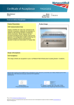
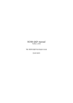
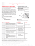
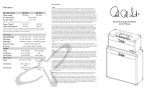
1
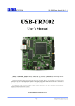
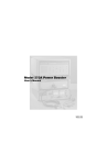
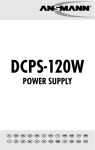
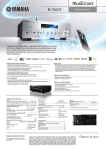
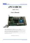
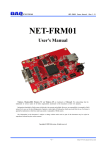
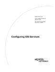
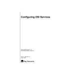
USB-LT02 Users Manual (Rev 1.0) USB-LT02 User’s Manual Windows, Windows2000, Windows NT and Windows XP are trademarks of Microsoft. We acknowledge that the trademarks or service names of all other organizations mentioned in this document as their own property. Information furnished by DAQ system is believed to be accurate and reliable. However, no responsibility is assumed by DAQ system for its use, nor for any infringements of patents or other rights of third parties which may result from its use. No license is granted by implication or otherwise under any patent or copyrights of DAQ system. The information in this document is subject to change without notice and no part of this document may be copied or reproduced without the prior written consent. Copyrights 2005 DAQ system, All rights reserved. -1- http://www.daqsystem.com USB-LT02 Users Manual (Rev 1.0) -- Contents -1. Introduction 2. USB-LT02 Function 3. Installation 3.1 Confirm Product Contents 3.2 Installation Process 4. USB-LT02 Board 4.1 USB-LT02 Description 4.2 Memory Map 4.3 Connector Pin-out 4.4 Sample Program 5. Test 5.1 Input Test 5.2 Output Test Appendix A.1 Dimension A.2 Schematic A.3 Application Circuit(Isolation I/O) A.4 USB-LT02(B) Reference -2- http://www.daqsystem.com USB-LT02 Users Manual (Rev 1.0) 1. Introduction USB-LT02 can control external device through simple provided API using even the developer who can never know USB. Connection with the outside uses a screw terminal and it can easily connect. There is special all-around board which it is prepared a TEST POINT. A simple circuit installs it to own board. You don’t need to use separately power supply for simple test because USB-LT02 uses PC power. Specially, an automation system and the input/output circuit which can operate are composed. Just usable to the automation control module that it don’t damage to external equipment and own module. Figure 1-1 shows that simple test to control 220V lamp with USB-LT02. [Figure 1-1. USB-LT02 Action] (Notice) 1. It can control the maximum AC/DC 350V in case of port 54 ~ 57, can use continuously the minimum 130mA under. (Refer to Figure 3-1.) 2. It can control the maximum AC/DC 60V in case of port 50 ~ 53 and port 40 ~ 47, can use continuously the minimum 550mA under. (Refer to Figure 3-1.) -3- http://www.daqsystem.com USB-LT02 Users Manual (Rev 1.0) 2. USB-LT02 Function The USB-LT02 has simple structure for easy I/O connection as like Figure 1-1. To connection USB and I/O take charge of the 8Bit Micro Controller, the command set equally use the 8051 command set. Each I/O port can set up whether or not there is what a user uses by input or output. USB-LT02 USB Interface USB Low Speed Device 2.0 Specification SIE 16Byte USB FIFO Two 16Bit Timer/Counter 8Bit CPU 8051 Compatible Program Instruction Input/ Output I/O Port1 Isolated Photo coupler Input I/O Port4 Isolated Solid State Relay Output I/O Port5 Isolated Solid State Relay Output I/O Port6 Isolated Photo coupler Input I/O Port7 Isolated Photo coupler Input ROM(OTP) 16KByte RAM 256Byte [Figure 2-1. USB-LT02 Functional Block Diagram] Internal program memory is taken possession of programmed firmware, program memory is OTP (One Time Programmable) type. GENERAL DESCRIPTION Low Speed device 1.5Mbps USB HID Interface 8051 Compatible Instruction set 4 clocks per Instruction cycle 16K EPROM, 256Bytes RAM USB Bus Powered -4- http://www.daqsystem.com USB-LT02 Users Manual (Rev 1.0) APPLICATION Factor y Automation , Home Automation USB Data acquisition(Temperature/Humidit y/voltage/current USB I/O Control, Remote Control Factor y Control Module Light Illumination Control SPECIFICATION ▣ Interface ▪ USB Powered through USB-B connector MAX 500mA ▪ +5V Single Power Operation ▪ 16 Isolated Photo-coupler Input ▪ 16 Isolated Solid state Relay Output ▣ Functions(Micro-Controller) ▪ Two 16bit Timer/Counter ▪ User configuration I/O Schmitt trigger input Schmitt trigger input with pull –up N-Ch open drain output N-Ch open drain output with pull-up ▪ One Control endpoint ▪ Two Data endpoint ▪ 30 external interrupt source ▣ External connection ▪ 4pin USB B-type connector ▪ 28pin DIP form -factor Pin-out ▪ 6 Test Point ▪ 40 screw terminal SOFTW ARE ▣ Operating System ▪ W indows 2000/XP ▣ Application Programming Interface ▪ W indows Client DLL API ▣ Software Development ▪ W indows Application by User ▪ Custom USB Device Firmware ▪ Custom W indows Client DLL -5- http://www.daqsystem.com USB-LT02 Users Manual (Rev 1.0) 3. Installation You confirm whether or not the packing contents are in good order before installation. 3.1 Confirm Product Contents [Figure 3-1. USB-LT02 Product Contents] Product Contents 1. USB-LT02 Board 2. USB(A-B) Cable 3. CD (Manual/Source etc.) -6- http://www.daqsystem.com USB-LT02 Users Manual (Rev 1.0) 3.2 Installation Process For USB-LT02 board installation to PC is as follows. There isn’t a Jumper to especially to set up for board installation in case of USB boards as it is Plug & Play devices. Also, there is no need to install of device driver because of HID (Human Interface Device) connection in case of USB-LT02. (1) First, open the box and connect to PC through USB cable. (2) The opposite side of USB cable connects to USB-LT02 board. (3) If cable connection succeeds, LED light on for indication of board supply. (4) It confirms a driver normally installation in the following ways. Do the following steps to show up the “Device Manager” window. [My Computer -> Properties -> Hardware -> Device Manager -> Human Interface Devices -> “HID-compliant device” [Figure 3-1. “System Properties” window] -7- http://www.daqsystem.com USB-LT02 Users Manual (Rev 1.0) [Figure 3-2. “System Properties” window] -8- http://www.daqsystem.com USB-LT02 Users Manual (Rev 1.0) [Figure 3-3. Device Manager Window] -9- http://www.daqsystem.com USB-LT02 Users Manual (Rev 1.0) 4. USB-LT02 Board In this chapter, the primary functions of the board are described briefly. For more information, refer to the device specification. 4.1 USB-LT02 Description USB-LT02 Board P70 P71 P12 P13 P1C1 P14 P15 P16 P17 P1C2 P60 P61 P62 P63 P6C1 P64 P65 P66 P67 P6C2 LED1 USB-LT02 DAQ system www.daqsystem.com 28 27 26 25 24 23 22 21 20 19 18 17 16 15 SW1 6.00 USB B type Connector Micom 1 2 3 4 5 6 7 8 9 10 11 12 13 14 LED2 P57 P56 P55 P54 P5C2 P53 P52 P51 P50 P5C1 P47 P46 P45 P44 P4C2 P43 P42 P41 P40 P4C1 [Figure 4-1. USB-LT02 Out-side View] In case of USB-LT02 as above picture, can easily use I/O, simple circuit is composed it to own all-around USB-LT02 board. Each component explanation is as follows. (1) USB B type Connector The USB-LT02 board connects to the PC through the USB A-B cable. The power supply and data gives and takes through this cable. -10- http://www.daqsystem.com USB-LT02 Users Manual (Rev 1.0) (2) LED1 It can confirm whether or not there is a stability of a board. (3) LED2 It confirms supply power to board. (4) MICOM It is 8bit Micro Controller which has the 8051 compatible command set. It takes charge of I/O and USB data communication. (5) SW1 Board reset button. (6) P70, P71, P12, P13, P1C1 It is a Photo-coupler Input Terminal. The input voltage can use 12V ~ 24V, no power polarity in design. VCC 2.4K P1C1 Port 7.0 P70 VCC 2.4K Port 7.1 P71 VCC From External To Micom Port 2.4K Port 1.2 P12 VCC 2.4K Port 1.3 P13 [Figure 4-2. Photo-coupler Input Circuit] -11- http://www.daqsystem.com USB-LT02 Users Manual (Rev 1.0) (7) P14, P15, P16, P17, P1C2 It is a Photo-coupler Input Terminal. The input voltage can use 12V ~ 24V, no power polarity in design. The circuit is same like Figure 4-2. (8) P60, P61, P62, P63, P6C1 It is a Photo-coupler Input Terminal. The input voltage can use 12V ~ 24V, no power polarity in design. The circuit is same like Figure 4-2. (9) P64, P65, P66, P67, P6C2 It is a Photo-coupler Input Terminal. The input voltage can use 12V ~ 24V, no power polarity in design. The circuit is same like Figure 4-2. (10) P57, P56, P55, P54, P5C2 It is a Photo Morse (Semiconductor Relay) Output Terminal. The maximum control voltage is 350V, continuously current is 130mA. P4C1 000 VCC Port 4.0 P40 000 P41 Port 4.1 From Micom Port 000 To External P42 Port 4.2 000 P43 Port 4.3 [Figure 4-3. Photo Morse (Semiconductor Relay) Output Circuit] -12- http://www.daqsystem.com USB-LT02 Users Manual (Rev 1.0) (11) P53, P52, P51, P50, P5C1 It is a Photo Morse (Semiconductor Relay) Output Terminal. The maximum control voltage is 60V, continuously current is 5500mA. The circuit is same like Figure 4-3. (12) P47, P46, P45, P44, P4C2 It is a Photo Morse (Semiconductor Relay) Output Terminal. The maximum control voltage is 60V, continuously current is 5500mA. The circuit is same like Figure 4-3. (13) P43, P42, P41, P40, P4C1 It is a Photo Morse (Semiconductor Relay) Output Terminal. The maximum control voltage is 60V, continuously current is 5500mA. The circuit is same like Figure 4-3. (Notice) You shall certainly use it within prescribed voltage and current. Otherwise, a product can be damaged. -13- http://www.daqsystem.com USB-LT02 Users Manual (Rev 1.0) 4.2 Memory Map The board has a program memory and data memory as like general 8051. The program memory area is OTP type. User can not reprogram it because of the board was programmed to supply in case of shipment. So, if you want special program, (You need more speedy response and private application) please contact to DAQ system. 16KByte Program Memory 256Byte Data Memory [Figure 4-4. Memory Map] -14- http://www.daqsystem.com USB-LT02 Users Manual (Rev 1.0) 4.3 Connector Pin-out The board has two connectors. There are the USB-B connector for USB communication, the PIN-OUT of DIP IC type connector for external I/O and power. And there is several test points. USB-B type is a connector for High speed USB connection. Figure 4-5 and Table 1 shows the connector and its pin description. 2 1 USB B type Connector 3 4 [Figure 4-5. USB-B Connector(Front View)] [Table 1. USB-B Connector] No. Name Description 1 VCC 2 D- USB Signal Minus(Negative) 3 D+ USB Signal Plus(Positive) 4 GND Remark USB Power +5V USB Power GND -15- http://www.daqsystem.com USB-LT02 Users Manual (Rev 1.0) USB-LT02 Board P70 P71 P12 P13 P1C1 P14 P15 P16 USB-LT02 P17 P1C2 P60 P61 P62 P63 P6C1 P64 DAQ system P65 P66 P67 P6C2 LE D1 Www.daqsystem.com 28 27 26 25 24 23 22 21 20 19 18 17 16 15 USB B type Connector SW1 MICOM 1 2 3 4 5 6 7 8 9 10 11 12 13 14 LE D2 P57 P56 P55 P54 P5C2 P53 P52 P51 P50 P5C1 P47 P46 P45 P44 P4C2 P43 P42 P41 P40 P4C1 [Figure 4-6. PIN-OUT of Screw Terminal Type] [Table 2. Screw Terminal PIN-OUT] Name Description Remark P70 Port 7.0 Photo Coupler Input Refer to Figure 4-2. P71 Port 7.1 Photo Coupler Input Refer to Figure 4-2. P12 Port 1.2 Photo Coupler Input Refer to Figure 4-2. P13 Port 1.3 Photo Coupler Input Refer to Figure 4-2. P70, P71, P12, P13 Common Input Refer to Figure 4-2. P14 Port 1.4 Photo Coupler Input Refer to Figure 4-2. P15 Port 1.5 Photo Coupler Input Refer to Figure 4-2. P16 Port 1.6 Photo Coupler Input Refer to Figure 4-2. P17 Port 1.7 Photo Coupler Input Refer to Figure 4-2. P1C1 -16- http://www.daqsystem.com USB-LT02 Users Manual (Rev 1.0) P14, P15, P16, P17 Common Input Refer to Figure 4-2. P60 Port 6.0 Photo Coupler Input Refer to Figure 4-2. P61 Port 6.1 Photo Coupler Input Refer to Figure 4-2. P62 Port 6.2 Photo Coupler Input Refer to Figure 4-2. P63 Port 6.3 Photo Coupler Input Refer to Figure 4-2. P60, P61, P62, P63 Common Input Refer to Figure 4-2. P64 Port 6.4 Photo Coupler Input Refer to Figure 4-2. P65 Port 6.5 Photo Coupler Input Refer to Figure 4-2. P66 Port 6.6 Photo Coupler Input Refer to Figure 4-2. P67 Port 6.7 Photo Coupler Input Refer to Figure 4-2. P64, P65, P66, P67 Common Input Refer to Figure 4-2. P57 Port 5.7 Photo Morse(Semiconductor Relay) Output Refer to Figure 4-3. P56 Port 5.6 Photo Morse(Semiconductor Relay) Output Refer to Figure 4-3. P55 Port 5.5 Photo Morse(Semiconductor Relay) Output Refer to Figure 4-3. P54 Port 5.4 Photo Morse(Semiconductor Relay) Output Refer to Figure 4-3. P54, P55, P56, P57 Common Output Refer to Figure 4-3. P53 Port 5.3 Photo Morse(Semiconductor Relay) Output Refer to Figure 4-3. P52 Port 5.2 Photo Morse(Semiconductor Relay) Output Refer to Figure 4-3. P51 Port 5.1 Photo Morse(Semiconductor Relay) Output Refer to Figure 4-3. P50 Port 5.0 Photo Morse(Semiconductor Relay) Output Refer to Figure 4-3. P53, P52, P51, P50 Common Output Refer to Figure 4-3. P47 Port 4.7 Photo Morse(Semiconductor Relay) Output Refer to Figure 4-3. P46 Port 4.6 Photo Morse(Semiconductor Relay) Output Refer to Figure 4-3. P45 Port 4.5 Photo Morse(Semiconductor Relay) Output Refer to Figure 4-3. P44 Port 4.4 Photo Morse(Semiconductor Relay) Output Refer to Figure 4-3. P44, P45, P46, P47 Common Output Refer to Figure 4-3. P43 Port 4.3 Photo Morse(Semiconductor Relay) Output Refer to Figure 4-3. P42 Port 4.2 Photo Morse(Semiconductor Relay) Output Refer to Figure 4-3. P41 Port 4.1 Photo Morse(Semiconductor Relay) Output Refer to Figure 4-3. P40 Port 4.0 Photo Morse(Semiconductor Relay) Output Refer to Figure 4-3. P43, P42, P41, P40 Common Output Refer to Figure 4-3. P1C2 P6C1 P6C2 P5C2 P5C1 P4C2 P4C1 (Notice) 1. It can control the maximum AC/DC 350V in case of port 54 ~ 57, can use continuously the minimum 130mA under. 2. It can control the maximum AC/DC 60V in case of port 50 ~ 53 and port 40 ~ 47, can use continuously the minimum 550mA under. -17- http://www.daqsystem.com USB-LT02 Users Manual (Rev 1.0) [Table 3. DIP IC PIN-OUT] Pin No. Name Description Remark 1 P53 Bit 3 of Port 5 2 P52 Bit 2 of Port 5 3 P51 Bit 1 of Port 5 4 P50 Bit 0 of Port 5 5 P47 Bit 7 of Port 4 6 P46 Bit 6 of Port 4 7 P45 Bit 5 of Port 4 8 P44 Bit 4 of Port 4 9 P43 Bit 3 of Port 4 10 P42 Bit 2 of Port 4 11 P41 Bit 1 of Port 4 12 P40 Bit 0 of Port 4 13 P66 Bit 6 of Port 6 14 GND 15 P65 Bit 5 of Port 6 16 P17 Bit 7 of Port 1 3 17 P16 Bit 6 of Port 1 3 18 P15 Bit 5 of Port 1 3 19 P14 Bit 4 of Port 1 3 20 P13 Bit 3 of Port 1 3 21 P12 Bit 2 of Port 1 3 22 P71 Bit 1 of Port 7 23 P70 Bit 0 of Port 7 24 P57 Bit 7 of Port 5 25 P56 Bit 6 of Port 5 26 P55 Bit 5 of Port 5 27 P54 Bit 4 of Port 5 28 +5V 2 Power Ground, Supply power to external board. USB power +5V, Supply power to external board. -18- http://www.daqsystem.com USB-LT02 Users Manual (Rev 1.0) [Table 4. Test Point PIN-OUT] Name Description Remark TP0 Bit 0 of Port 6 2 TP1 Bit 1 of Port 6 2 TP2 Bit 2 of Port 6 2 TP3 Bit 3 of Port 6 2 TP4 Bit 4 of Port 6 2 (Remark) 1. A bit 7 of Port6 is connected to LED2, this bit is set up to output. If output is “Low” and “ 0V”, LED2 light on. 2. There is a circuit to limit current to internal in case of Port6. If LED light on, there is no need to limit special current resistor to external. 3. The port1 has same specification of port1 of standard 8051. In other words, it can set up weak pull-up only. 4.4 Sample Program A sample program is provided to make the user get familiar with the board operation. There is no installation of special driver because USB HID device is used to driver with supported Windows system. The sample program has two programs. One is a program to decision whether the board is strange action or not. The other is a program to set up I/O of each port and to control output. [Figure 4-7. Sample Program 1] -19- http://www.daqsystem.com USB-LT02 Users Manual (Rev 1.0) [Figure 4-8. Sample Program 2, When “All Input” Click] To run the sample application program, you need to use API (Application Programming Interface), which is a form of client DLL. To compile the sample source to make its executable file, you have to use Import Library files and Header files. You can find them in the CDROM. On --- LED On of each port. Off --- LED Off of each port. All Input --- The LED lights on all ports as [Figure 4-8]. All Output --- The LED goes out all ports as [Figure 4-9]. -20- http://www.daqsystem.com USB-LT02 Users Manual (Rev 1.0) [Figure 4-9. When “All Output” Click] -21- http://www.daqsystem.com USB-LT02 Users Manual (Rev 1.0) 5. Test 5.1 Input Test This chapter is for test to learn how to operate a board and check the abnormality of a board. The test performs it at the PC which a USB-LT02 board was installed as it use a program of “sample1.exe” in an EXE folder of CDROM. The execution file and source file of sample1 and sample2 is in App and App0 folder of CDROM. The execution file use a test, a user modifies a necessary a sample source file that provided it usable. [Figure 5-1. Sample1.exe] In the left LED is on at the above pictures, in the right LED is off. If an input of bit1 of port6 is “1’, LED is on, on the contrary to this, LED is off. In other words, If TP0 connect to VCC (+5V), LED is on. IF TP0 connect to GND, LED is off. At this time, the bit1 of port6 is used to set up by input at the above programs. -22- http://www.daqsystem.com USB-LT02 Users Manual (Rev 1.0) 5.2 Output Test (1) You can test of output function through LED is on/off in a board at below pictures. [Figure 5-2. LED On/Off Display] In the top LED is off, in the bottom LED is on. If an output of bit7 of port6 is “0’, LED is on, on the contrary to this, LED is off. User can test to press “ON/OFF” button at the Sample1 programs. -23- http://www.daqsystem.com USB-LT02 Users Manual (Rev 1.0) Appendix A.1 Dimension 115.6 107.9 P70 P71 P12 P13 P1C1 P14 P15 P16 P17 P1C2 P60 P61 P62 P63 P6C1 P64 P65 P66 P67 P6C2 40.6 USB-LT02 USB B type Connector 83.8 91.4 P57 P56 3.2 x 4 P55 P54 P5C2 P53 P52 P51 P50 P5C1 P47 P46 P45 P44 P4C2 P43 P42 P41 P40 P4C1 < Top View > 10.7 10.0 1.6 < Right Side View > -24- http://www.daqsystem.com USB-LT02 Users Manual (Rev 1.0) A.2 USB-LT02 Schematic USB-LT02 is making our USB-LT with basis, use same circuit. -25- http://www.daqsystem.com USB-LT02 Users Manual (Rev 1.0) A.3 Application Circuit (Isolation Input/Output) It is used in the automations that used PC in case of USB-LT02 in order to simply input/output that it used the established serial (RS232), parallel (printer) ports. The advantage of USB-LT02 has no program confliction because of using exclusive USB source, on the other hand, RS232 and printer ports have a confliction between programs because of using common source. Also, control Input/output is possible as provide 31 I/O. If it exchange an input and output between different equipment like factory automations etc., it use a photo-coupler isolation in order to not to affect with mutual interference and influence at the below pictures. External Power Board Power R External Device IN < Photo-coupler Input Circuit> External Power Board Power R External Device OUTN <Photo-coupler Output Circuit> A register value at the above pictures can use properly selection which it fit to the external power. The industry power mainly uses 5V, 12V, 24V, 48V. -26- http://www.daqsystem.com USB-LT02 Users Manual (Rev 1.0) A.4 USB-LT02(B) We are selling the board which composed an interface section only USB-LT02(B) Type for USB-LT user. It control input in case of USB-LT02(B) as it use USB-LT. [Figure A4-1. USB-LT02(B) Board] [Figure A4-2. USB-LT Board] -27- http://www.daqsystem.com USB-LT02 Users Manual (Rev 1.0) [Figure A4-3. The connection with LT02(B) and USB-LT] -28- http://www.daqsystem.com USB-LT02 Users Manual (Rev 1.0) References 1. USB 2.0 System Architecture -- Don Anderson, USB SIG(www.usb.org) 2. Universal Serial Bus Specification -- Compaq/Intel/Microsoft/NEC, MindShare Inc. (Addison Wesley) 3. USB-LT User’s manual -- DAQ system 4. AN201 How to build application using APIs -- DAQ system 5. AN342 USB-LT02 API VER1.0 -- DAQ system -29- http://www.daqsystem.com