1
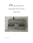
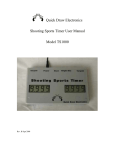
Quick Draw Electronics
Audience/Shooter Display User Manual
Rev. B October 2011
WELCOME TO THE QUICKDRAW ELECTRONICS AUDIENCE/SHOOTER DISPLAY.
THE BASIC SYSTEM CONSISTS OF:
1 INTERFACE BOX
1 OR MORE AUDIENCE/SHOOTER DISPLAYS
1 INTERFACE TO TIMER CABLE OR COMPUTER TO INTERFACE CABLE
1 POWER SUPPLY
SETUP
Two Displays and one Timer
1.
2.
3.
4.
5.
6.
7.
Connect the Power supply Output to the Interface box by plugging in and turning clockwise about
¼ turn. It should lock in place with a click. Refer to the diagram for Audience display connections
for a timer driven 2 lanes.
Connect one end of the display Cable to Output1 of the interface box. Connect the other end of the
cable to the input of the Display for lane1.
Connect one end of the cable to the output of lane 1 display. Connect the other end of the cable to
the input of lane 2 display.
Connect the power cable into the AC input of the power supply. Connect the other end of the
power cable into an AC outlet.
Connect the timer as instructed in the timer user manual
Connect one end of the timer to display interface cable into the interface box input labeled Timer.
Connect the other end of the cable into the timer data connector.
You are ready to go.
Computer Driven up to 4 lanes
1.
2.
3.
4.
5.
6.
7.
Connect the Power supply Output to the Interface box by plugging in and turning clockwise
about ¼ turn. It should lock in place with a click. Refer to the diagram for Audience display
connections for a computer driven up to 4 lanes.
Connect one end of the display Cable to Output1 of the interface box. Connect the other end of
the cable to the input of the Display for lane1.
Connect one end of the cable to the output of lane 1 display. Connect the other end of the cable to
the input of lane 2 display. Continue connecting input to output for all displays.
Connect the power cable into the AC input of the power supply. Connect the other end of the
power cable into an AC outlet.
Connect the Computer as instructed in the Computer Software user manual
Connect the remaining end of the computer to display interface cable into the interface box input
labeled USB.
You are ready to go.
Computer Driven 5 to 8 lanes
1.
2.
Connect the Power supply Output to the Interface box by plugging in and turning clockwise
about ¼ turn. It should lock in place with a click. Refer to the diagram for Audience display
connections for a computer driven 5 to 8 lanes.
Connect one end of the display Cable to Output1 of the interface box. Connect the other end of
the cable to the input of the Display for lane1.
3.
4.
5.
6.
7.
8.
Connect one end of the cable to the output of lane 1 display. Connect the other end of the cable to
the input of lane 2 display. Continue connecting input to output for all displays.
Connect one end of a cable to the output of the last Display. Connect the other end of the cable to
the Input 8 on the interface box.
Connect the power cable into the AC input of the power supply. Connect the other end of the
power cable into an AC outlet.
Connect the Computer as instructed in the Computer Software user manual
Connect the remaining end of the computer to display interface cable into the interface box input
labeled USB.
You are ready to go.
Display Mounting
THE CASE OF THE DISPLAY IS CONSTRUCTED FROM HARDWOOD BUT CAN BE CHIPPED BY
A WAX BULLET THAT IS PLACED EXACTLY IN THE WRONG SPOT. IT IS RECOMMENDED
THAT THE DISPLAY BE MOUNTED BEHIND A CUTOUT IN A WOOD OR METAL PLATE TO
KEEP THE DISPLAY LOOKING NEW. THE DISPLAY ITSELF IS PROTECTED BY A PIECE OF
LEXAN AND DOES NOT REQUIRE ANY FURTHER PROTECTION.
THE DISPLAY IS MOUNTED BY ¼-20 SCREWS, TWO ON EACH SIDE OF THE DISPLAY. THE
SCREWS CAN INSERT A MAXIMUM OF 1-1/2 INCHES INTO THE BOX MEASURED FROM THE
OUTSIDE OF THE BOX.
Display usage
The display shows the time of the last shot on the four digits of the display with the first
digit indicating the seconds and a decimal point which is always lit. The other three digits
display the time in tenths, hundredths, and thousandths of a second. The decimal point of
these three digits is used to indicate the number of wins that the shooter has in the current
contest. The first win will light the tenths of a second decimal point which is also
annotated by the W just below the decimal point. The second win will illuminate both the
tenth seconds and hundredth seconds’ decimal point. The third win will illuminate all
three decimal points. This function is only supported when the Personal Computer
software is used. The decimal point win indication is not supported when the display is
connected directly to the timer in a two display setup.
OPTIONAL EQUIPMENT
UP TO 8 AUDIENCE DISPLAYS CAN BE USED TOGETHER WITH THE SAME POWER SUPPLY
AND INTERFACE BOX. IF ADDITIONAL LANES ARE REQUIRED, ADDITIONAL POWER
SUPPLY/INTERFACE BOXES WILL NEED TO BE PURCHASED.
PERSONAL COMPUTER SOFTWARE IS ALSO AVAILABLE AS SHOWN IN THE ABOVE SETUP
DIAGRAM.
WARRANTY
THE AUDIENCE DISPLAY IS WARRENTEED AGAINST DEFECTS IN MATERIALS AND
WORKMANSHIP TO THE ORIGINAL PURCHASER FOR ONE YEAR FROM DATE OF
PURCHASE. THE PURCHASE IS AUTOMATICALLY REGISTERED WITH QUICK DRAW
ELECTRONICS UPON PURCHASE. NO ADDITIONAL WARRANTY REGISTRATION IS
REQUIRED.