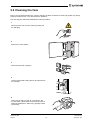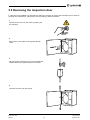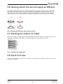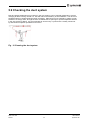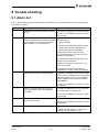
1
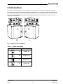
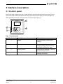
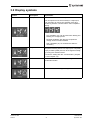
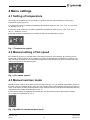
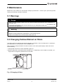
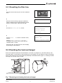
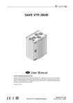
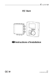
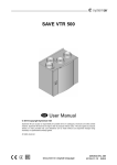
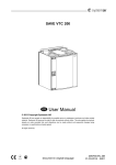
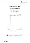
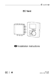
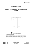
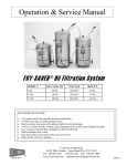
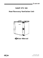
SAVE VTC 300
Heat Recovery Ventilation Unit
User Manual
207233-EN_GB
25-01-2011V.A-002
Contents
1 Warnings................................................................................................................................... 1
2 Introduction ............................................................................................................................... 2
3 Interface description................................................................................................................... 3
3.1 Control panel ................................................................................................................... 3
3.2 Display symbols ............................................................................................................... 4
4 Menu settings ............................................................................................................................ 5
4.1 Setting of temperature ...................................................................................................... 5
4.2 Manual setting of fan speed .............................................................................................. 5
4.3 Manual summer mode ...................................................................................................... 5
5 Maintenance.............................................................................................................................. 6
5.1 Warnings ......................................................................................................................... 6
5.2 Changing Outdoor/Extract air filters ................................................................................... 6
5.2.1 Resetting the filter time............................................................................................ 7
5.3 Checking the heat exchanger ............................................................................................ 7
5.4 Cleaning the fans ............................................................................................................. 8
5.5 Removing the Inspection door ........................................................................................... 9
5.6 Cleaning extract louvres and supply air diffusers ................................................................10
5.7 Checking the outdoor air intake .........................................................................................10
5.8 Check roof cowl................................................................................................................10
5.9 Checking the duct system .................................................................................................11
6 Trouble shooting ........................................................................................................................12
6.1 Alarm list..........................................................................................................................12
1 Warnings
The following admonitions will be presented in the different sections of the document.
Danger
• Make sure that the mains supply to the unit is disconnected before performing any maintenance or
electrical work!
• All electrical connections and maintenance work must be carried out by an authorized installer and
in accordance with local rules and regulations.
Warning
• The system should operate continuously, and only be stopped for maintenance/service.
• The installation of the unit and complete ventilation system must be performed by an authorized
installer and in accordance with local rules and regulations.
• Beware of sharp edges during mounting and maintenance. Use protective gloves.
• Although the Mains supply to the unit has been disconnected there is still risk for injury due to rotating
parts that have not come to a complete standstill.
• Make sure that filters are mounted before starting the unit.
• This product is not intended to be used by children or people with reduced physical or mental ability
or lack of experience and knowledge, if no instruction concerning the use has been given by the
person responsible for their safety or that this person is supervising the operation. Children should be
supervised so that they can not play with the product.
Caution
• Do not connect tumble dryers to the ventilation system
• Duct connections/duct ends must be covered during storage and installation
SAVE VTC 300
207233
User Manual
1
Systemair AB
2 Introduction
The SAVE VTC 300 is a heat recovery ventilation unit with a built in counter flow plate heat exchanger.
There are two model options, right (R) and left (L) model (figure 1). The different models are recognized by
the control panel which is situated on the right side of the unit in an (R) unit and on the left side in an (L) unit.
This manual describes basic information how to operate and perform maintenance on the unit and the
system it is connected to.
D
C
B
A
A
R
B
D
C
L
Fig. 1 Right and Left models
Table 1: Symbol description
Description
Symbol
A
Supply air
B
Exhaust air
C
Outdoor air
D
Extract air
SAVE VTC 300
207233
User Manual
2
Systemair AB
3 Interface description
3.1 Control panel
The control panel is built into the unit on either the left or right hand side panel sections of the VTC 300.
The control panel is always situated on the same side of the unit as the supply air connection (figure 1)
Below illustration shows the control panel with a short description (figure 2)
Fig. 2 Control panel
Position
Description
Explanation
1
Display
Shows symbols, menus and
settings
2
Selection knob
Move through the menu lists or
change settings and values by
turning the knob left or right
3
Confirm button
Confirm menu choices or settings
by pressing the button
4
Back button
Step back in the menu levels by
pressing the button
SAVE VTC 300
207233
User Manual
3
Systemair AB
3.2 Display symbols
Symbol
Description
Explanation
Fan speed
Illustrates the current set fan speed.
The fan speed can be set manually in 3 steps (min,
nom and max) by turning the selection knob and
confirming with the “confirm button” after completed
setting.
A
B
C
• Low ventilation (A): Can be used when leaving the
building for a longer period
• Nominal ventilation (B): Will give required air
change under normal conditions
• High ventilation (C): To increase the airflow if
necessary
Temp
Illustrates the current set temperature. The
temperature setting is done in 5 steps (from completely
empty to filled symbol) and can be changed manually
by turning the “selection knob”.
Confirm the setting with the “confirm button” (chapter
4.1 and chapter 4.3).
Service
Access to the service menu by pressing the
confirmation button
Alarm
Access to the alarm list by pressing the confirm button
SAVE VTC 300
207233
User Manual
4
Systemair AB
4 Menu settings
4.1 Setting of temperature
The supply air temperature is set manually in 5 steps in the main menu display by choosing the
temperature symbol (figure 3).
If an electrical or water re-heater is installed the temperature steps are 12.0, 14.5, 17.0, 19.5 and 22.0
°C. Default is 12.0 °C.
If the unit is used without any re-heater installed the temperature steps are 15.0, 16.0, 17.0, 18.0 or
19.0 °C . Default is 15.0 °C.
Each step increase is illustrated by increasing the filling of the temperature symbol.
Fig. 3 Temperature symbol
4.2 Manual setting of fan speed
It’s possible at any time to manually set the fan speed in the main menu display. By choosing the fan
symbol and confirming (figure 4) it’s possible to increase or decrease the fan speed in the 3 steps, Low,
Nom and High. By doing so you override the programmed week schedule for the unit until the end of the
present time period in the week program.
Fig. 4 Fan speed symbol
4.3 Manual summer mode
Manual summer mode for VTC 300 occurs if one step lower than 12 °C is selected (temperature symbol on
the main menu is completely empty, figure 5). This means that the bypass damper opens If the re-heater is
active, it will switch off during manual summer mode. Manual summer mode aborts automatically after two
minutes when the supply air temperature is ≤ 5 °C.
If water heater battery is installed and activated the manual summer mode is aborted if the outdoor
air or supply air temperature is ≤ 5 °C.
Fig. 5 Symbol for manual summer mode
SAVE VTC 300
207233
User Manual
5
Systemair AB
5 Maintenance
Maintenance of the SAVE VTC 300 should normally be performed 3 - 4 times a year. Apart from general
cleaning the following should be observed:
5.1 Warnings
Danger
• Make sure that the Mains supply to the unit is disconnected before performing any maintenance or
electrical work!
• All electrical maintenance work must be carried out by an authorized installer and in accordance with
local rules and regulations.
Warning
• The system should operate continuously, and only be stopped for maintenance/service
• Beware of sharp edges during maintenance. Use protective gloves.
• Make sure that filters are mounted before starting the unit
5.2 Changing Outdoor/Extract air filters
The filters cannot be cleaned and must be changed as necessary. This is normally done 1–2 times per
year depending on the air pollution at the installation site.
When it’s time to change the filters an alarm is shown in the control panel display. When this occurs
do the following:
1. Change filters as shown in below illustration (figure 6).
2. Reset the filter time as described below (chapter 5.2.1). Depending on the condition of the filter, you
might need to change the operation time for the filter.
Fig. 6 Changing of filters
SAVE VTC 300
207233
User Manual
6
Systemair AB
5.2.1 Resetting the filter time
1
Go to the service menu by the use of the selection
knob
2
Password
Enter the service level by typing the password.
Use the selection knob for each digit and confirm
with the “confirm button” after each set digit.
1 1 1 1
3
Service
Go down to Filter period, confirm
Change password
→Filter period
Date/Time
4
Filter period
Choose Reset:
confirm.
YES with the “selection knob”,
Reset:
NO
Time to replace 9 month
Change Time to replace 9 month if
necessary to the time of your choice with the
“selection knob”, confirm.
Step back until you reach the main menu display
by pressing the “back button”.
5.3 Checking the heat exchanger
Even if the required maintenance as described in is carried out (chapter 5.2), dust will build up in the
exchanger block. It is therefore of vital importance for the upkeep of a high efficiency that the exchanger
block is removed from the unit and cleaned periodically as illustrated below (figure 7). Cleaning the heat
exchanger can be done every 3 years.
2
1
Fig. 7 Removing and cleaning the heat exchanger
SAVE VTC 300
207233
User Manual
7
Systemair AB
5.4 Cleaning the fans
Even if the required maintenance, such as changing of filters is carried out, dust and grease may slowly
build up inside the fans. This will reduce the efficiency.
The fans may be cleaned as illustrated in below procedure.
1
Disconnect the unit from the mains by pulling out
the wall plug
2
Remove the cover plates
3
Disconnect the fast couplings
4
Loosen the bracket holding the fan and pull the fan
out carefully
5
Clean the fan using a cloth or a soft brush. Do
not use water. White spirit can be used to remove
obstinate settlements. Allow to dry properly before
remounting.
SAVE VTC 300
207233
User Manual
8
Systemair AB
5.5 Removing the Inspection door
In case the unit is installed in a tight space it might be necessary to remove the inspection door to perform
cleaning and maintenance. Remove the door according to below procedure.
1
Disconnect the unit from the mains by pulling out
the wall plug.
2
Remove the cover plate of the bypass damper
motor.
3
Disconnect the modular plug from the modular jack
situated behind the bypass damper cover plate.
4
Unscrew the door from the hinges.
SAVE VTC 300
207233
User Manual
9
Systemair AB
5.6 Cleaning extract louvres and supply air diffusers
The system supplies fresh air to your home and extracts the used indoor air via the duct system and
diffusers/louvres. Diffusers and louvres are mounted in ceilings/walls in bedrooms, living room, wet
rooms, WC etc. Remove diffusers and louvres (figure 8) and wash in hot soapy water as required
(diffusers/louvres must not be exchanged). Cleaning of diffusers/louvres can be done as necessary.
Fig. 8 Removing diffusers and extract louvres
5.7 Checking the outdoor air intake
Leaves and pollution could plug up the air intake grille (figure 9) and reduce the capacity. Check the air
intake grille, and clean as necessary. It is recommended to do this at least twice a year.
Fig. 9 Outdoor air intake grill
5.8 Check roof cowl
The roof cowl (if fitted) connected to the exhaust air duct needs to be checked at least twice a year and
cleaned as necessary.
VTC 300
207233
User Manual
10
Systemair AB
5.9 Checking the duct system
Dust and grease settlements may build up in the duct system, even if required maintenance such as
changing of filters is being carried out. This will reduce the efficiency of the installation. The duct runs
should therefore be cleaned/changed when necessary. Steel ducts can be cleaned by pulling a brush
soaked in hot soapy water, through the duct via diffuser/louvre openings or special inspection hatches
in the duct system (if fitted). It is recommended to do this every 5 years and is normally carried out
by authorized companies specialized in this area.
Fig. 10 Cleaning the duct system
SAVE VTC 300
207233
User Manual
11
Systemair AB
6 Trouble shooting
6.1 Alarm list
Error is warned with text and warning triangle in the display. Turn menu selector to the warning triangle
and press 2 x confirm.
Alarm
Explanation
Do the following
Fan
Indicates error on either supply or extract
air fan.
The alarm is displayed in the control panel.
Indicates triggered overheat protection (in
case of installed electric re-heater battery)
or frost protection (in case of installed
water heating– or cooling battery).
A triggered frost protection alarm results
in the following:
EMT/Frost
Contact your installation company or place
of purchase.
• Both fans stop.
• Outdoor and exhaust air dampers close.
• Water valve opens completely (10 V
signal goes out to the actuator).
The unit will restart once the water
temperature reaches +5K over set frost
protection temperature.
A triggered over heat protection gives an
alarm in the control panel.
Reset by pushing the red button on the
front of the heater.
If the problem continues contact your
installation company or place of purchase.
DAMP
Indicates malfunction in bypass damper.
The alarm is displayed in the control panel
The unit will not be able to use the bypass
damper for defrosting, i.e. stop defrosting
will be initiated if a re-heater is installed
and activated.
Contact your installation company or place
of purchase
Pb Fail
Error in connection with relay card for
the electrical re-heater (if installed and
activated).
The alarm is displayed in the control panel.
The heater will not be activated.
Contact your installation company or place
of purchase.
Temp
Filter
Malfunction in one or more of the
temperature sensors.
The alarm is displayed in the control panel.
Time for filter change.
The alarm is displayed in the control panel.
Contact your installation company or place
of purchase.
Change filter according to instructions
(chapter 5.2 and chapter 5.2.1).
SAVE VTC 300
207233
User Manual
12
Systemair AB
SAVE VTC 300
207233
User Manual
13
Systemair AB
lastpage
Systemair AB reserves the right to make changes and improvements to the contents
of this manual without prior notice.
Systemair AB
Industrivägen 3
SE-739 30 Skinnskatteberg, Sweden
Phone +46 222 440 00
Fax +46 222 440 99
www .systemair. com
207233