1
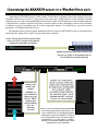
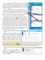
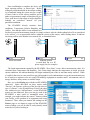
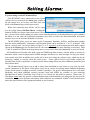
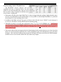
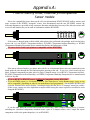
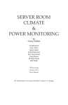
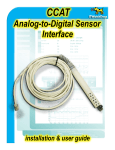
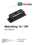
RTAFHD3
Remote Temperature /
Airflow / Humidity Sensor
installation & user guide
RTAFHD3
Remote Temperature / Airflow / Humidity Sensor
While every model of the WeatherGoose monitoring system includes (at least) a built-in temperature sensor,
and several models also include built-in humidity or airflow sensors, it’s often desirable to be able to monitor
these conditions at multiple locations from a single central display, especially if you have a medium-to-large data
center or server room with multiple cabinets located at various distances from a central air-conditioning system.
The RTAFHD3 Remote Temperature / Airflow / Humidity Sensor allows you to monitor up to sixteen remote
locations at once from a single WeatherGoose. (The MiniGoose/XP-II, with its built-in 16 sensor ports, can
accommodate all sixteen RTAFHD3 sensors directly; other models will require the use of one or more external
bus-splitters to expand the number of ports.) Note that 16 is the maximum number of sensors which can be used
on any one WeatherGoose, and the use of bus-splitters does not expand this maximum number; bus-splitters only
expand the number of physical connection points.
The RTAFHD3 sensor is available with cable lengths of 12 ft. (3.65m), 20 ft. (6.1m), and 50 ft (15.24m) as
standard options. Custom cable lengths can also be requested for specific applications. Keep in mind when
ordering multiple sensors, or sensors with custom lengths, that WeatherGoose system has a maximum limit of
600 ft. of total cable length on the Digital Sensor Bus; i.e. you can have twelve 50 ft. sensors, or ten 50 ft. sensors
plus five 20 ft. sensors, or any other combination of cable lengths as long as (A) the number of sensors does not
exceed sixteen, and (B) the cable lengths do not add up to more than 600 ft. total. (Note that other Digital Sensor
Bus devices, such as CCATs and temperature sensors, must also be added into these totals if present.)
The RTAFHD3 sensor is compatible with any WeatherGoose (series I or series II) monitoring unit which has
Digital Sensor Bus connections – however, there are some important compatibility issues to beware of if you are
running older firmware revisions or have older RTAF2/RTAFH2 sensors installed already, so please read the next
section carefully!
RTAFHD3 Remote Temperature / Airflow / Humidity Sensor users’ guide – Rev. A-101 (Dec. 2010)
IMPORTANT!
RTAFHD3 is a new (as of 3rd quarter of 2010) addition to our product line. Previously, we offered two
different, similar sensor models: RTAFH2 and RTAF2 (with and without humidity sensing, respectively), and
RTHD2 (temperature & humidity without airflow measurement). These models have since been discontinued in
favor of RTAFHD3, which is a significantly improved design offering better resolution, smoother response to
airflow changes, and increased stability. If you purchased your WeatherGoose series-II monitoring unit at the
same time as your RTAFHD3 sensors, and you don’t have any existing “legacy” sensors or monitoring units
which you intend to mix with the new devices, you should not experience any compatibility issues, since your
monitoring unit will have already shipped with the correct firmware revision to support RTAFHD3 sensors.
However, if you are attempting to add RTAFHD3 sensors to an already-existing WeatherGoose
installation which you purchased and set up in the past, please read and be aware of the following firmware
and system-compatibility requirements:
MINIMUM FIRMWARE VERSION REQUIRED TO SUPPORT RTAFHD3 SENSORS:
Ÿ If you are using a Series-I WeatherGoose unit: v2.94 or higher is required
Ÿ If you are using a Series-II WeatherGoose unit: v3.5.0 or higher is required
If your WeatherGoose unit is currently running a firmware revision prior to these, you will need to visit the
Support area of our web site (www.itwatchdogs.com) to download and install the appropriate firmware
upgrade for your particular model prior to connecting the RTAFHD3 sensors. If you attempt to connect the
RTAFHD3 to a unit with firmware older than the versions listed above, it will not be recognized by the
WeatherGoose; either an “Unknown Device” or an incorrect sensor type will appear in the Sensors page, and the
sensor will not function properly.
COMPATIBILITY WITH PREVIOUS SENSOR DEVICES:
WARNING: The RTAFHD3 is not compatible with the previous RTAF2 and RTAFH2 sensors! If you
have an existing WeatherGoose installation with one or more of these older sensors attached, you will need to
disconnect and remove them before attempting to connect any RTAFHD3 sensors to that WeatherGoose.
Attempting to mix RTAF2/RTAFH2 and RTAFHD3 sensors on a single WeatherGoose monitoring unit will
cause data-communication errors on the Digital Sensor Bus, and none of the sensors will function properly. (If
this happens, the WeatherGoose unit will display a warning message advising you which legacy sensor(s) are
causing a data-bus conflict and ask you to remove them.) This incompatibility between RTAF2/RTAFH2 and
RTAFHD3 applies to all WeatherGoose models and firmware revisions.
Note: there may also be compatibility issues with certain versions of the RTHD2 (temperature / humidity /
dewpoint) sensors, especially ones manufactured before the 4th quarter of 2010. Again, the WeatherGoose will
display a warning message if you have an incompatible RTHD2 connected once you try to attach an RTAFHD3.
Other Digital sensor types, such as the RT temperature sensors and the CCAT analog-to-digital converters,
are not affected by this incompatibility, and can be used in conjunction with RTAFHD3.
If you are not certain whether you currently have any of the older RTAF2 or RTAFH2 sensors in service, we
have provided some diagrams in Appendix A: How to Identify Old vs. New AirFlow Sensor Models to assist you
in determining which type(s) of sensors you have.
ITWatchDogs apologizes for the inconvenience. Any customers who need to add RTAFHD3 sensors to
existing WeatherGoose installations with RTAF2, RTAFH2, or RTHD2 sensors attached are invited to contact
our sales department to discuss upgrade options. Depending on the sensor model(s) and when they were
originally purchased, you may be eligible for a free or reduced-cost trade-in of RTAF2/RTAFH2 sensors for
RTAFHD3, and/or modification of their older RTHD2 sensors to be compatible with RTAFHD3.
Connecting an RTAFHD3 sensor is fairly simple. Each sensor is equipped with a 6p6c modular plug (also
sometimes referred to as an “RJ-11” plug, since it’s the same style of plug used in US-style telephone systems)
which fits into one of the corresponding Digital Sensor Bus sockets on a WeatherGoose climate monitoring unit.
A WeatherGoose will have anywhere from one to sixteen of these sockets, depending on the model in question;
in addition, a passive bus-splitter may be used to expand the number of available ports, up to the system’s
maximum of 16 Digital Sensor Bus devices.
The diagrams below provide a general illustration of how to connect an RTAFHD3 sensor to a WeatherGoose
monitoring unit, along with a couple of typical application examples:
sensor wand is placed at the actual location
where you desire to measure the ambient
temperature, humidity, and airflow
modular plug at the end of the RT data cable
fits into one of the corresponding jacks on
the WeatherGoose monitoring unit
measure the
intake and
outflow
conditions of
your cabinets to
make sure your
HVAC / CRAC
cooling units
and circulating
fans are
operating
correctly
monitor the temperatures
inside a storage cabinet for
independent verification that
the temperature and humidity
has remained within
acceptable storage limits for
the materials (paper stock,
pharmaceuticals, archived
records, etc.) stored inside
(note: we do not recommend using the RTAFHD3
sensor inside refrigerated storage areas, as the
sensor elements are not waterproofed against
condensation or frost accumulation. We also do
not recommend the sensor be used in outdoor
environments, or in areas where it could be
exposed to concentrated chemical vapors which
could attack the sensor elements.)
Mounting an RTAFHD3 sensor is also fairly simple. Since the sensor is purely electronic, rather than
mechanical, it isn’t absolutely dependant on being aimed in any particular direction with respect to the direction
of airflow; the only requirement is that the airflow must pass over or through the open end of the tube, where the
sensing elements are exposed via the cutout slots. (The sensor may provide slightly better response if the sensor
is mounted such that the circuit board is perpendicular to the airflow direction, as shown below, but this is not a
requirement.)
THIS ORIENTATION
GENERALLY GIVES
THE BEST RESPONSE
EITHER OF THESE
ORIENTATIONS
WILL ALSO WORK
Any of the above mounting orientations will provide acceptable airflow response. However, mounting it such
that the airflow is coming from behind the sensor, as shown here, will not work.
THIS ORIENTATION WILL
GIVE POOR AIRFLOW RESULTS
As you connect each RTAFHD3-series Remote Temperature
Sensor to the WeatherGoose, it will appear in the unit’s web interface
where you can examine the current readings, look at the graphed
history (if any), and set alarm thresholds. (Note that the following
example screenshots, unless indicated differently, are of a series-II unit
running v3.5.1 firmware.)
In the example shown here, we see a WeatherGoose-II unit with
two sensors connected. Notice that when they are first connected to
the unit, both of them are named “AF/HTD Sensor”, which is the
default name for an RTAFHD3 sensor. The only way to distinguish
them is by their device ID numbers, which are shown in the right-hand
side of the title bar for each sensor block, as highlighted here.
For this reason, when connecting multiple sensors for the first time,
we recommend that you only connect one RTAFHD3 at a time, wait
for it to appear in the Sensors page, then make a note of its ID number
and, if desired, change its name to a more meaningful one via the
“friendly names” settings on the Display tab. (We will touch on this
briefly in a moment; or you may refer to the user manual for your
particular WeatherGoose model for more detailed instructions.) You
may also wish to use a fine-point marker or a stick-on label to mark the
device ID and friendly name on the cable or the plastic tube, to assist
you in identifying each device during or after installation. Then, after
you have identified and marked the first device, connect the next one
in turn, and repeat this procedure until all RTAFHD3s have been
connected and properly identified.
Ÿ If you are using a series-II WeatherGoose
model:
When you first connect an RTAFHD3 sensor to
a Series-II unit, its sensor block will look like this.
Notice the word “Calibrating” in the Airflow
reading?
Since the sensor uses a thermaldifferential method for measuring air flow, the
ambient air temperature around the sensor can
influence the readings; therefore, whenever an
RTAFHD3 sensor is first powered up, it spends a
minute or two recalibrating itself to compensate for
these air-temperature effects. Be aware that during
this brief calibration period, the sensor is not measuring airflow, and no alarms will be tripped if the airflow goes
above or below any alarm thresholds you may have set! Temperature, humidity, and dewpoint readings are not
affected by this recalibration delay and will begin logging and alarming immediately upon connection.
Ÿ If you are using a series-I WeatherGoose
model:
When you first connect an RTAFHD3 to a
Series-I unit, it will not display the word
“calibrating”; it will simply show a reading of “0”
during the calibration process. This is a limitation
of the series-I firmware.
Once recalibration is complete, the device will
begin reporting airflow, as shown here. Before
setting any alarm thresholds on the airflow reading,
we recommend letting the system run for a couple
of hours, both to let the sensors stabilize and to
gather a representative sample of data that will give
you a good idea of what range of airflow high/low
readings are considered “normal” for your
particular installation.
The RTAFHD3 directly measures three
conditions: Temperature, Relative Humidity, and
Airflow. Note that the airflow is not calibrated to a
fixed scale or unit of measurement; instead, it is simply a relative value in which readings below 20 are considered
to be “still air” (i.e. no appreciable airflow within the vicinity of the sensor), while readings above 20 indicate
increasing airflow as the number rises towards 100, as illustrated below.
no air movement
moderate airflow
(a small desk fan or a PC
power-supply fan, for example)
high-speed airflow
The fourth measurement reported by the RTAFHD3, “Dew Point”, is not a direct measurement; rather, it is
calculated from Temperature and Humidity. Dew Point simply indicates the temperature at which, given the
current conditions, the ambient humidity will begin condensing out of the air and onto nearby surfaces. While
it’s unlikely that a server room would ever get cold enough for such condensation to occur, this measurement may
be of interest to customers who are using ITWatchDogs equipment to monitor non-IT environments such as
storage facilities, utility rooms, or machine shops.
Here, we see the Display page with the two RTAFHD3s
connected. Notice that there are three entries under
“Devices”; the first one, at the top of the list with a device
type of “climate”, is the WeatherGoose-II itself; the other
two, with device type “airFlowSensor”, are the RTAFHD3
sensors we just connected. Here, you can give each of the
RTAFHD3s a more useful or meaningful name; for
example, you might indicate the sensor’s location within
your facility, or the position of an equipment rack being
monitored. Then, when you examine the readings on the
Sensors page or set alarms to trigger off the RTAFHD3
sensor readings, you will be able to easily identify which
sensor device you are looking at.
If you are using a series-II WeatherGoose:
Each RTAFHD3 sensor connected to to the system
will have its own section on the Alarms page, similar to
the one shown here, just as they each have their own
block on the Sensors page as shown previously.
When first connected, these blocks will be empty
save for a single button, Add New Alarms. Clicking this
button will add a new alarm event to that sensor’s block;
here, you can choose which reading you want to set an alarm threshold on, set the threshold itself, specify whether
the alarm is to trip when the monitored temperature goes above or below the desired threshold, and which
action(s) are to occur when the threshold is exceeded.
The RTAFHD3 allows you to set alarms on the Temperature, Humidity, AirFlow, and Dewpoint readings
from the sensor; additionally, Temperature and Dewpoint alarms can be set either in °C or °F, as desired. Note
that on a series-II unit, you can set alarms in either °C or °F regardless of the temperature-scale display option
chosen on the Display page; the WeatherGoose-II will convert the threshold values internally as necessary. Both
°C and °F options are offered on the drop-down menu, so you can use them interchangeably as suits your needs.
All WeatherGoose-II models offer both e-mail and SNMP-trap alarm actions, with the ability to selectively
determine which e-mail recipients and/or SNMP managers should receive alert messages for any given alarm;
some models also offer an audible siren, and/or one or more low-voltage dry-contact relays, which can also be
selectively enabled to activate when the alarm occurs. Future add-on devices may further expand the
WeatherGoose-II unit’s capabilities, in which case the alarm-settings block may show additional options beyond
those shown above.
The WeatherGoose-II allows you to add as many alarm thresholds to each sensor as you wish, up to the
system’s maximum of 200 alarms, which allows you to set up a series of escalating alarm conditions depending
on how far the sensor’s readings exceed the “normal” setpoint(s). For specific information on how to set alarm
thresholds, and which additional action(s) beyond e-mail and SNMP are available on your particular
WeatherGoose-II model, consult the Setup Guide & User Manual for the model in question. (Please note: IT
Watchdogs cannot make any specific recommendations about what threshold(s) are appropriate for your specific
installation; it is up to the end user to determine what conditions are considered “normal” based on observation
and/or the specifications of the equipment installed at your location.)
If you are using a Series-I WeatherGoose:
The RTAFHD3 sensors’ behavior will be
essentially the same as described above, but the
alarms are set somewhat differently, and you do not
have as wide a range of options as with the newer
series-II units. In particular:
Ÿ Each sensor will offer only a single High-Trip (i.e. alarm is tripped when the reading is higher than this value)
and Low-Trip threshold for each measurement; it is not possible to add multiple thresholds to a particular
measurement to set up escalating alarm events.
Ÿ In addition, both High- and Low-Trip types are always active; the only way to “disable” a given trip type is
to set it to a value that is well beyond the expected operating range.
Ÿ Thresholds can only be set in the same temperature scale (°C or °F) set on the Display page. CAUTION: If
you subsequently change the Display setting from one scale to the other, you will need to manually reprogram
all of your alarm thresholds as well, as the series-I WeatherGoose will not automatically convert between °C
and °F scales for you!
Ÿ The series-I software does not support selectively determining which e-mail recipients receive alerts for which
alarms; all e-mail recipients specified in the e-mail configuration page will automatically receive all alarm
messages. Also, the series-I software does not provide for traps to be sent to more than one SNMP manager,
and there are no series-I models which offer dry-contact relay outputs.
Appendix A:
How to Identify Older, Potentially-Incompatible
Sensor models:
Due to the compatibility issues between the old, now-discontinued RTAF2/RTAFH2 airflow sensors (and
some versions of the RTHD2 “dewpoint” sensor, also discontinued) and the new RTAFHD3 sensors, the
following diagrams are provided to help customers determine whether they have any of the old-style sensors still
in service and whether they can be used in combination with the RTAFHD3.
If the sensor is housed inside a thick-walled white plastic tube perforated with multiple small circular holes
at one end, it is an RTAF2 (Temperature/Airflow), RTAFH2 (Temperature/Airflow/Humidity), or RTHD2
(Temperature/Humidity/Dewpoint) device manufactured before the 2nd quarter of 2008.
No sensor devices in this style of tube are compatible with the RTAFHD3!
If the sensor is housed inside a grey plastic tube with five or six horizontal slots at one end, examine the circuit
board inside the tube through the slots and through the opening at the end. If you see a circuit board with two
black, D-shaped components on either side of a single U-shaped cutout, it is an RTAF2 (Temperature/Airflow),
RTAFH2 (Temperature/Airflow/Humidity), or RTHD2 (Temperature/Humidity/Dewpoint) device manufactured
in 2008 or beyond.
If it is an RTAF2 or RTAFH2 sensor, it will not be compatible with the RTAFHD3.
Ÿ If it is an RTHD2 sensor (i.e. if it identifies itself as “Dew Point Sensor” on the Sensors page), it may or may
not be compatible, depending on when it was manufactured and programmed. (Incompatible RTHD2s will
cause the WeatherGoose unit to display a warning message that the device is causing a sensor-bus conflict.
If this occurs, contact our sales department to inquire about having the sensor replaced or modified to work
alongside RTAFHD3.)
If, on the other hand, the circuit board inside the sensor has a more complex-looking series of cutouts,
including two cylindrical components stretched across a pair of U-shaped cutouts, with a single flat square
component visible at the spade-shaped tip, it is an RTAFHD3.