1
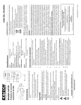
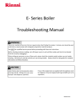
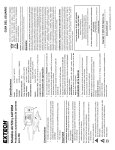
CCAT
Analog-to-Digital Sensor
Interface
installation & user guide
CCAT Analog-to-Digital Sensor Interface
Most models of the WeatherGoose climate-monitoring systems provide at least three Analog Inputs for use
with sensors such as current transformers, water sensors, smoke alarms, or other types of sensors whose outputs
are a simple dry-contact closure, a variable resistance, or a proportional 0-5Vdc signal voltage. Some models,
such as the RelayGoose-II, provide as many as six such inputs.
Sometimes, however, this simply isn’t enough for a particular application – especially applications which
involve multiple sensors that generate actual voltage signals, such as the RCP2-100 City Power Monitor or the
CT30-60-120 Current Transformer, since these devices cannot be “doubled up”, i.e. connected either in series or
parallel to allow more than one sensor to share a single input. (Whereas dry-contact sensors, such as the MS-1
Magnetic Door Switch, can be connected this way, subject to certain restrictions.) For these kinds of applications,
one or more CCAT Analog-to-Digital Sensor Interfaces can be used to expand the number of analog inputs, and
thus the number of analog sensors.
CCATs can also make some types of analog sensors easier to use. Since a CCAT can be specifically
programmed to match the type of analog sensor connected to it, it can interpret the sensor’s conductivity or
voltage signal into the proper human-readable scale and measurement units, instead of simply providing a generic
reading of 0 ~ 99 the way a WeatherGoose’s built-in analog inputs do.
Finally, the CCAT is essential for attaching these types of sensors to models such as the MiniGoose, which
do not provide any built-in analog inputs.
The CCAT is compatible with all models of the WeatherGoose system which provide at least one Digital
Sensor Bus connection for external sensors. (Thus, it is not compatible with the MicroGoose unit, which does
not have any connections for external digital sensors.) It is not compatible with the WeatherDuck, which is a
legacy product which is no longer actively sold or supported by ITWatchDogs.
Note: the CCAT has been manufactured in two different physical variations over the lifetime of the product.
If yours does not look like the Revision B version pictured below, please consult Appendix A for information
about the previous Rev.A model. (Regardless of revision, the two versions function the same way.)
Also note: on most WeatherGoose models, there is a 600 ft. limit on the total length of Digital Sensor Bus
cabling. The analog wiring from the CCAT’s input terminals to the sensor(s) themselves does not count against
this 600 ft. limit! For example, if you had two CCATs with 12-foot data cables attached to a single unit, each
connected to a WD-100 (water sensor with a 100 ft. cable), your “total cable length” for the Digital Sensor Bus
would only be 24 ft. (12+12), not 224 ft. (12+12+100+100). However, we do still recommend trimming any
excess wire lengths, to keep excessively long runs from acting as antennas that could pick up ambient EM
interference and introduce noise or inaccuracies into the sensor readings.
current (Rev.B) CCAT
CCAT analog-to-digital sensor interface users’ guide – Rev. A-101 (Nov. 2010)
Connecting a CCAT Analog-to-Digital Interface is fairly simple. Each CCAT is equipped with a 6p6c
modular plug (also sometimes referred to as an “RJ-11” plug, since it’s the same style of plug used in US-style
telephone systems) which fits into a corresponding Digital Sensor Bus socket on a WeatherGoose climate
monitoring unit. A WeatherGoose will have anywhere from one to sixteen of these sockets, depending on the
model in question; in addition, a splitter may be used to expand the number of available ports, up to the system’s
maximum of 16 Digital Sensor Bus devices.
The diagrams below provide a general illustration of how to connect a CCAT device to a WeatherGoose
monitoring unit and to a variety of sensors.
BK
RD
(Note: unless specified otherwise, the examples which follow will be shown using one or more CCATDIGITAL “generic digital” devices connected to a WeatherGoose-II unit. Any differences between other types
of CCAT or WeatherGoose models will be highlighted as necessary.)
modular plug at the end of the CCAT data
cable fits into one of the corresponding jacks
on the WeatherGoose monitoring unit
As you connect each CCAT to the WeatherGoose, it will
appear in the unit’s web interface where you can examine the
current readings, look at the graphed history (if any), and set alarm
thresholds.
In the example shown here, we see a WeatherGoose-II unit
with two CCAT-DIGITAL devices connected. (The CCATDIGITAL is the “generic digital” model, designed for use with any
arbitrary dry-contact switch or relay, and is the model we will use
for most of the following examples unless specifically indicated
otherwise.) Notice that when they are first connected to the unit,
both of them are named “Digital Sensor”, which is the default name
for a CCAT-DIGITAL device. The only way to distinguish them
is by their device ID numbers, which are shown in the right-hand
side of the title bar for each sensor block, as highlighted here.
For this reason, when connecting multiple CCAT devices for
the first time, we recommend that you only connect one CCAT at
a time, wait for it to appear in the Sensors page, then make a note
of its ID number and, if desired, change its name to a more
meaningful one via the “friendly names” settings on the Display
tab. (We will touch on this briefly in a moment; or you may refer
to the user manual for your particular WeatherGoose model for
more detailed instructions.) You may also wish to use a fine-point
marker or a stick-on label to mark the device ID and friendly name
on the cable and/or the plastic housing, to assist you in identifying
each device during or after installation. Then, after you have
identified and marked the first CCAT device, connect the next one in turn, and repeat this procedure until all
CCATs have been connected and properly identified.
Here, we see the Display page with the two CCATs connected.
Notice that there are three entries under “Devices”; the first one, at
the top of the list with a device type of “climate”, is the
WeatherGoose-II itself; the other two, with device type
“digitalSensor”, are the CCAT-DIGITAL devices we just
connected. Here, you can give each of the CCATs a more useful
or meaningful name; for example, you might indicate the sensor’s
location within your facility, or the number of an equipment rack
being monitored, or the name of a particular dry-contact signal
from a generator or equipment panel. Then, when you examine the
readings on the Sensors page or set alarms to trigger off the
CCATs, you will be able to easily identify which CCAT-andsensor combination you are looking at.
As mentioned previously, the CCAT is programmed to match a particular type of analog-voltage or drycontact sensor. This programming is done at the factory before the device is shipped, and allows the CCAT to
“scale”, or interpret, the incoming 0 ~ 5Vdc signal, or the open/closed state of a dry-contact switch or relay, to a
reading that’s more easily interpreted by the user. (As opposed to the behavior of the WeatherGoose’s built-in
Analog Inputs, which can only display a “generic” 0 ~ 99 reading since the WeatherGoose currently has no
provision for “knowing” what kind of analog sensor is attached to its input terminals.)
The following diagrams give a quick overview of the various CCAT types and an example of the hookup
methods for their associated sensors. Note that these are only simple examples; for more detailed information on
using a CCAT with an analog sensor, including how to set appropriate alarm thresholds for that type of sensor
and how those sensors can be expected to behave in operation, please refer to the Installation & User Guide for
that particular sensor. (These guides can be downloaded from our web site.)
A special note for users of our previous “Series-I” WeatherGoose models: The analog-sensor product line
has expanded over time, and therefore so has the line of matching CCATs. This means that not all models of
CCAT are supported by all Series-I firmware revisions; if you attempt to connect a CCAT which was introduced
after your model’s firmware version, it will not be recognized and will probably result in either an “Unknown
Device” or an incorrect sensor type appearing in the Sensors page. If this should occur, consult Appendix B to
verify whether or not your firmware revision supports the CCAT type you’re trying to add, and upgrade your
firmware if necessary. Also, the operation of the CCATs may be subtly different on a Series-I unit, in terms of
reading scales or setting alarm thresholds, than the Series-II behaviors touched upon here. Again, specific
information on how a given CCAT/sensor combination will behave with a Series-I unit can be found in the
Installation & User Guide for the particular sensor in question.
As of this writing, all existing CCAT types are supported by all existing revisions of Series-II firmware.
Ÿ CCAT-30
This model is designed for use with the 30VDCM 30V Battery Monitor, which is a device that allows the
WeatherGoose to monitor the state of negative-ground 12V or 24V battery banks such as are often found in UPS
backup-power systems, or in remote facilities that may use a mix of solar, generator, and battery power. When
this sensor is connected through a CCAT, the WeatherGoose is able to display a true representation of the battery
voltage, rather than requiring the user to perform a manual calculation to convert the generic Analog Inputs’ 0 ~
99 reading into the sensor’s 0 ~ 30Vdc range.
Only one 30VDCM can be connected to a CCAT-30; if you have multiple battery banks to be monitored, you
will need one CCAT-30 for each 30VDCM sensor.
red wire goes into the terminal marked RD or (+)
RD
BLACK wire with ring terminal
goes to (–) battery terminal
RED wire with ring terminal
goes to (+) battery terminal
CCAT-30
BK
30VDCM
black wire goes into the terminal marked BK or (-)
Ÿ CCAT-48
This model is designed for use with the 48VCD-1 Telecom Battery Voltage Monitor, which is a device
that allows the WeatherGoose to monitor the state of the positive-ground, –48Vdc battery systems commonly
used in telephone systems. When this sensor is connected through a CCAT, the WeatherGoose is able to display
a true representation of the battery voltage, complete with the proper mathematical sign, as referenced to ground
(or 0V), rather than requiring the user to perform a manual calculation to convert the generic Analog Inputs’ 0 ~
99 reading into the sensor’s –16 ~ –60Vdc range.
Only one 48VCD-1 can be connected to a CCAT-48; if you have multiple battery banks to be monitored, you
will need one CCAT-48 for each 48VCD-1 sensor.
red wire goes into the terminal marked RD or (+)
RD
BLACK wire with ring terminal
goes to (–) battery terminal
RED wire with ring terminal
goes to (+) battery terminal
CCAT-48
BK
48VCD-1
black wire goes into the terminal marked BK or (-)
Ÿ CCAT-CPM
This model is designed for use with the RCP2-100 City Power Monitor, which is a device which, when
plugged into a wall socket not connected to your UPS or backup generator, can alert you to when your facility
loses incoming line power (assuming your WeatherGoose and network do have backup power available, of
course). When this sensor is connected through a CCAT, the WeatherGoose is able to display the line-voltage
state as “on” or “off”, corresponding to a numeric analog reading above or below 50, rather than requiring the
user to remember the significance of the numeric values as they would if the RCP2-100 was connected directly
to the Analog Inputs. (The RCP2 only provides a fixed “power good” signal; it doesn’t actually measure the line
voltage.)
Only one RCP2-100 can be connected to a CCAT-CPM; if you have multiple power circuits or phases to be
monitored, you will need one CCAT-CPM for each City Power Monitor.
BK
RD
striped wire goes into the terminal marked RD or (+)
black wire goes into the terminal marked BK or (-)
Ÿ CCAT-CUR
This model is designed for use with the CT30-60-120 Split-Frame Current Transformer, which is a device
that clamps on to a current-carrying AC wire and allows the WeatherGoose to measure the current flow through
that wire. When this sensor is connected through a CCAT, the WeatherGoose is able to display a true
representation of the current draw, rather than requiring the user to perform a manual calculation to convert the
generic 0 ~ 99 reading into the sensor’s 0-30A range. (Note, however, that if the transformer is set to its 60A or
120A range, the user will still need to multiply the displayed reading by 2 or 4, as appropriate, since the CCAT
and WeatherGoose have no way of knowing what the range switch on the CT30-60-120 is set to.)
Only one CT30-60-120 can be connected to a CCAT-CUR; if you have multiple power circuits or phases to
be monitored, you will need one CCAT-CUR for each current transformer.
Black wire
goes to (-)
Red wire goes to (+)
Amperage Range
120
60
30
BK
RD
red wire goes into the terminal marked RD or (+)
black wire goes into the terminal marked BK or (-)
–
+
Output
0~5 VDC
Ÿ CCAT-DOOR
This model is designed for use with the MS-1 Magnetic Door Switch, which is a simple magnet switch that
can be used to alert you when a cabinet door is opened or closed. When this sensor is connected through a CCAT,
the WeatherGoose will show the door switch as “Open” or “Closed”, corresponding to a numeric value of 99 or
0 respectively due to the way the CCAT’s analog-to-digital converter chip interprets the absence or presence of
loop current through a closed or open circuit, rather than requiring the user to remember the significance of the
numeric values as they would if the door switches were connected directly to the Analog Inputs.
It is possible to string multiple MS-1 door switches together in series, so that they all share a single CCAT; in
this configuration, any single door switch opening will break the circuit and change the status. However, you
would not be able to determine which switch has been opened if you connect multiple MS-1s in series; if you need
to know this, then you will need one CCAT-DOOR for each door switch (or group of switches) you need to
individually monitor.
BK
RD
red wire goes into the terminal marked RD or (+)
black wire goes into the terminal marked BK or (-)
Ÿ CCAT-SMOKE
This model is designed for use with the SA-1 Smoke Alarm, which is a standard AC line-powered smoke
alarm that has additional circuitry to allow the WeatherGoose to see whether the alarm has activated or not. When
this sensor is connected through a CCAT, the WeatherGoose is able to display the line-voltage state as “smoky”
or “clear”, corresponding to a numeric analog reading above or below 50, rather than requiring the user to
remember the significance of the numeric values as they would if the smoke alarm was connected directly to the
Analog Inputs.
Only one SA-1 can be connected to a CCAT-SMOKE; if you have multiple SA-1 smoke alarms positioned
throughout several rooms or floors in your facility, and wish to monitor them all individually, you will need one
CCAT-SMOKE for each City Power Monitor.
BK
RD
red wire goes into the terminal marked RD or (+)
black wire goes into the terminal marked BK or (-)
Ÿ CCAT-WATER
This model is designed for use with the WD-1 Water Sensor, which is a simple conductivity sensor that can
be used to alert you when the surface under the WD-1 has become damp or wet from leaking water or other
conductive liquid. When this sensor is connected through a CCAT, the WeatherGoose will show the “dampness”
as an increasing conductivity value, with a value of 1 or 0 indicating that the surface under the sensor is dry, and
increasing values indicating that the surface is becoming increasingly damp and therefore conductive, which is
more intuitive than the “99 = dry, 1 = wet” behavior that would be seen if the WD-1 were connected directly to
the Analog Inputs.
It is possible to connect multiple WD-1 water sensors together in parallel, so that they all share a single
CCAT; in this configuration, any single sensor getting wet will cause the reading to change towards increased
conductivity. However, you would not be able to determine which sensor is damp if you connect multiple WD-1s
in parallel; if you need to know this, then you will need one CCAT-WATER for each WD-1 (or group of WD-1s)
you need to individually monitor.
BK
RD
red wire goes into the terminal marked RD or (+)
black wire goes into the terminal marked BK or (-)
In addition to the sensor-specific models mentioned in the previous section, ITWatchDogs also provides two
“generic” CCAT types for use with other manufacturers’ sensors and equipment whose functions and/or output
signals don’t exactly match the specific sensors listed previously. Together, these two CCAT models give you
additional flexibility in providing continuous, internet-enabled monitoring of the conditions inside your serverroom and data-center facilities.
Ÿ CCAT-DIGITAL
This model is designed for use with dry-contact switches or relays in general, such as might be found on an
alarm panel or a generator-monitoring system. It is also suitable for use with equipment which signals its status
via a 0 ~ 5Vdc signal voltage, where 0V = “off” and 5V = “on.”
Note that if your sensor is of the latter type, where it actively generates a voltage signal, it is important to
observe the correct polarity when connecting the signal source to the CCAT, as shown below. Incorrect hookup
can damage the CCAT, and/or cause unreliable or undefined behavior.
NC
BK
RELAY
COIL
NO
RD
Note also that the WeatherGoose only samples the sensors every 5 seconds or so; therefore, the CCATDIGITAL is most suitable for use with sensors and transducers whose values change relatively slowly over time,
or for alarms which will persist for several seconds after triggering. “Impulse” sensors which measure quick
transient events, such as accelerometers, or simple pushbutton switches, are generally not suitable.
C
When using a dry-contact relay or switch, as shown here, there is no need to worry about polarity,
as dry-contact pairs do not have a “positive” or “negative” side.
BK
RD
+
signal voltage (positive side) goes
into the terminal marked RD or (+)
–
signal return (ground or negative side)
goes into the terminal marked BK or (–)
However, when using a sensor which generates an active signal voltage, as shown here, it is
important to observe the correct polarity when connecting the signal to the CCAT.
NC
CCAT-DIGITAL
BK
RELAY
COIL
NO
RD
Depending on the type of sensor you have connected, you may need to do some experimentation or consult
with the device’s manufacturer to determine the sensor’s “normal” state in order to pick the proper alarmthresholds. As a general rule, however, a value of “1” from a CCAT-DIGITAL will correspond to either a 0Vdc
input or a closed dry-contact pair, as shown here:
C
normally-closed (NC) contact pair of a dry-contact
relay is closed, indicating the relay is inactive.
RD
+
BK
CCAT-DIGITAL
signal voltage is at 0Vdc,
indicating an inactive state.
–
either of these states corresponds to a
reading of “1” on the CCAT-DIGITAL,
indicated by the “OFF” message on the
Sensors page.
NC
CCAT-DIGITAL
BK
RELAY
COIL
NO
RD
While a value of “99” from a CCAT-DIGITAL corresponds to either a 5Vdc input or an open dry-contact pair,
as shown here:
C
normally-closed (NC) contact pair of a dry-contact
relay is open, indicating the relay has activated.
BK
RD
+
–
CCAT-DIGITAL
signal voltage is at 5Vdc,
indicating an active state.
either of these states corresponds to a
reading of “99” on the CCAT-DIGITAL,
indicated by the “ON” message on the
Sensors page.
Setting the alarm threshold to “50” and the alarm type to “High Trip” will cause that alarm setting to trip on
the ON state, because 99 is higher than 50, and to clear itself on the OFF state when the value drops to 1, which
is lower than 50. Conversely, setting the alarm threshold to “50” and the alarm type to “Low Trip” will trip that
alarm on the OFF state and clear it on the ON state.
Ÿ CCAT-ANALOG
This model is designed for use with sensors that output a proportional 0 ~ 5Vdc signal, such as a pressure
transducer, a sound-level sensor, or a gas-concentration sensor. The input signal must not exceed 5Vdc, and must
not go below ground (0Vdc). It may also be suitable for certain types of 4-20mA current-loop sensors, as long
as the sensor is powered by an external power supply and an appropriate load resistor is connected across the
CCAT inputs to convert the current signal to a voltage signal; the CCAT itself does not have a suitable load
resistor built in, and cannot supply sufficient loop current to drive a 4-20mA sensor directly.
Note that it is important to observe the correct polarity when connecting the signal source to the CCAT, as
shown below. Incorrect hookup can damage the CCAT, and/or cause unreliable or undefined behavior.
Note also that the WeatherGoose only samples the sensors every 5 seconds or so; therefore, the CCATANALOG is most suitable for use with sensors and transducers whose values change relatively slowly over time,
such as the environmental sensors mentioned above. “Impulse” sensors which measure quick transient events,
such as accelerometers, are generally not suitable.
RD
+
signal voltage (positive side) goes
into the terminal marked RD or (+)
BK
+5Vdc
0Vdc
–
signal return (ground or negative side)
goes into the terminal marked BK or (–)
When using a sensor which generates an active signal voltage, as shown here, it is important to
observe the correct polarity when connecting the signal to the CCAT.
4mA
external
power
–
RD
20mA
BK
250Ω
+
signal voltage (positive side) goes
into the terminal marked RD or (+)
signal return (ground or negative side)
goes into the terminal marked BK or (–)
Sensors which generate a 4-20mA current-loop signal may work with the CCAT-ANALOG if a
250-ohm load resistor is connected across the input terminals, as shown here, to convert the
current signal into a proportional voltage. For this application a 1/4-watt , 1% metal-film resistor
should be sufficient. Note that the sensor must be powered from an external source, as the CCATANALOG cannot supply loop current to run the sensor on its own.
Here, too, correct polarity must be observed when connecting the signal to the CCAT.
A CCAT-ANALOG acts similarly to the built-in Analog Inputs on a WeatherGoose unit, in that it displays
the 0 ~ 5Vdc input signal as a generic value ranging from 0 ~ 99. The primary difference between the
CCAT-ANALOG and the WeatherGoose Analog Inputs is that the CCAT-ANALOG does not have an internal
pull-up resistor to supply loop current to a dry-contact device, so it will not work as a generic multi-purpose input
that can accommodate dry-contact, conductivity, and/or voltage-signaling sensors the way the WeatherGoose’s
built-in inputs can. (This also means that a CCAT-ANALOG with nothing connected to its terminals will not
predictably read “99”; instead, the value will tend to “float” randomly.)
RD
+
BK
+5Vdc
CCAT-ANALOG
0Vdc
–
the varying 0 ~ 5Vdc output of an analog transducer is
shown as a 0 ~ 99 reading on the WeatherGoose graph.
As with the CCAT-DIGITAL, alarms can be set to trip when the sensor’s reading passes above or below a
threshold value. Depending on the type of analog transducer you have connected, you will probably need to do
some experimentation to determine what range of values are “normal” and what threshold(s) indicate an
“abnormal” or alarm state.
If you are using a Series-II WeatherGoose model, each CCAT connected to to the system will have its own
section on the Alarms page, similar to the one shown below, just as they each have their own block on the Sensors
page as shown previously.
When first connected, these blocks will be empty save for a single button, Add New Alarms. Clicking this
button will add a new alarm event to that sensor’s block; here, you can set the alarm threshold level, specify
whether the alarm is to trip when the monitored value goes above or below the threshold, and which action(s) are
to occur when the threshold is exceeded. Series-II WeatherGoose models offer both e-mail and SNMP-trap alarm
actions, with the ability to selectively determine which e-mail recipients and/or SNMP managers should receive
alert messages for any given alarm; some models also offer an audible siren, and/or one or more low-voltage
dry-contact relays, which can also be selectively enabled to activate when the alarm occurs. Firmware revisions
of v3.4.x and higher, as shown above, also offer the ability to set a trigger delay so that the sensor reading must
exceed the set threshold for a period of time before the alarm is tripped, and to set a repeating interval so that the
alarm message will be repeatedly sent for as long as the alarm stays tripped.
The Series-II WeatherGoose allows you to add as many alarm thresholds to each sensor as you wish, up to
the system’s maximum of 200 alarms, which allows you to set up a series of escalating alarm conditions
depending on how far the sensor’s readings exceed the “normal” setpoint(s). For specific information on how to
set alarm thresholds, and which action(s) are available for your particular Series-II WeatherGoose unit, consult
the Setup Guide & User Manual for the model in question.
For specific information on the appropriate alarm thresholds for a given CCAT-and-sensor combination,
consult the Installation & User Guide for the particular sensor in question.
If you are using a series-II
unit with a firmware revision
prior to v3.4.x, the alarm-settings
blocks will look like this. Alarm
settings are programmed the same
way as above; the only difference
(aside from the lack of triggerdelay and alarm-repeat intervals,
which were introduced in v3.4) is that the alarm types are named High Trip and Low Trip instead of Above
and Below, respectively. High Trip alarms are tripped when the reading goes higher than the set threshold,
while Low Trip alarms are tripped when the reading goes below the threshold. Otherwise, the alarms work the
same way as they do in the later firmware versions.
If you are using a Series-I
WeatherGoose, the CCAT alarm-settings
blocks will look similar to this. The
CCAT’s behavior will be essentially the
same as described above, but the alarms are
set somewhat differently, and you do not
have as wide a range of options as with the newer Series-II units. In particular:
Ÿ Each CCAT will offer only a single High-Trip and Low-Trip threshold. Series-I devices do not offer the
capability to add multiple alarm thresholds to a single sensor to set up escalating alarms.
Ÿ In addition, both the High- and Low-Trip thresholds are always active and must be set; the only way to
“disable” an unneeded threshold is to set it to a value that is beyond the sensor’s range. For most CCAT types,
this would mean setting High Trip to “110” if you only want to be alerted when a reading falls below a given
value, or setting Low Trip to “-10” if you only want to know when it goes above a given value – however,
some CCAT types may have different requirements to disable the unwanted alarm type (such as the
CCAT-48, which reports its sensor readings in negative numbers); consult the Installation & User Guide for
the particular sensor in question if necessary.
Ÿ Series-I devices do not support selectively determining which e-mail recipients receive alerts for which
alarms; all e-mail recipients specified in the e-mail configuration page will automatically receive all alarm
messages.
Ÿ Series-I devices do not support sending traps to more than one SNMP manager.
Ÿ There are no Series-I models which offer dry-contact relay outputs to control devices in response to alarms.
Ÿ Not all CCAT types are supported by all Series-I firmware revisions; refer to Appendix B for specifics
on the minimum firmware revision(s) necessary to support a particular CCAT type.
CCAT Analog-to-Digital Sensor Interface
Appendix A: older CCAT models
The CCAT has been made in two different physical forms since its original introduction. Although they are
functionally identical, their appearance is somewhat different; the current revision, also known as the “Rev.B”
model, consists of a long, narrow circuit board housed inside a
plastic tube, with a permanently-attached data cable and strain
relief on one end and a 2-position screw-terminal block on the
other; while the older Rev.A model, pictured here, consisted of
a circuit board housed inside a heat-shrink seal with a 6p6c
jack at each end and a pair of wires to connect the analog
sensor to.
While the Rev.A design has long been discontinued in favor of the current Rev.B model, the following
information is provided as a convenience to those users who may have purchased the older model in the past and
still have them in service.
The Rev.A CCAT is connected to the WeatherGoose unit by means of a short data cable with a 6p6c modular
plug at each end. The cable which was originally supplied with the Rev.A CCAT was 6 ft. in length, unless a
custom length was specified at the time of ordering, but if the original cable cannot be found (or is not long
enough for your needs) any suitable cable will do. The primary requirements are that (A) all six pins must be
wired “straight-through”, i.e. pin 1 to pin 1, pin 2 to pin 2, etc. without any signals crossing from one pin to
another, and (B) the total length of wiring on the digital sensor bus must not exceed 600ft. Note that it does not
matter which of the two 6p6c jacks on the CCAT you plug the data cable into.
Instead of a 2-position screw-terminal block, the Rev.A CCAT features a plain red and black wire pair to
connect the analog sensor to. The red wire corresponds to the RD or (+) terminal, while the black wire
corresponds to the BK or (–) terminal. Simply solder or crimp the analog sensor’s wires to the CCAT wires, then
cover the connections with heat-shrink tubing or electrical tape if necessary to prevent the red and black wire
connections from touching.
Aside from these physical differences, the rev.A CCATs function the same as the rev.B model described in
the main body of this user guide.
the red & black wire pair extending from
one end of the rev.A CCAT corresponds to
the RD(+) and BK(–) terminal block on the
rev.B CCAT, and is wired accordingly.
the data cable with 6p6c modular plugs at each end, supplied with
the CCAT, connects it to one of the corresponding jacks on the
WeatherGoose monitoring unit.
either of the rev.A CCAT’s jacks may be used, as they are connected
together internally and function identically to each other.
CCAT Analog-to-Digital Sensor Interface
Appendix B: Series-I firmware support for the
various CCAT models
While we always recommend that you keep your units, regardless of model, upgraded to the latest firmware,
we realize that some customers may have their own reasons for keeping their units “frozen” at a particular
revision. When it comes to the CCAT devices, this is not a problem for customers who have Series-II
WeatherGoose units, since all of the currently-existing CCAT types had already been developed by the time
Series-II was released; however, for customers running Series-I units, the CCAT product line has been expanded
over the lifetime of Series-I, and thus not all of the newer CCATs are supported by the older firmware revisions.
The following information is provided as a convenience to those Series-I users who need to see whether the
CCAT type they wish to use is supported by their existing firmware or not.
CCAT TYPE
CCAT-30
CCAT-48
CCAT-CPM
CCAT-CUR
CCAT-DOOR
CCAT-SMOKE
CCAT-WATER
CCAT-ANALOG
CCAT-DIGITAL
EARLIEST SERIES-I FIRMWARE WHICH
SUPPORTS THIS CCAT TYPE
v2.76
v2.76
v2.76
v2.22
v2.22
v2.76
v2.22
v2.76
v2.70