1
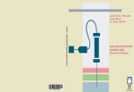
US Patent No. 6,481,300 (others pending)
Field Manual
© Copyright 2004, GeoInsight
Introduction
The HydraSleeve groundwater sampler can be used to collect a representative sample for most
physical and chemical parameters without purging the well. It collects a whole water sample
from a user-defined interval (typically within the well screen), without mixing fluid from other
intervals. One or more HydraSleeves are placed within the screened interval of the monitoring
well, and a period of time is allocated for the well to re-equilibrate. Hours to months later,
the sealed HydraSleeve can be activated for sample collection. When activated, HydraSleeve
collects a sample with no drawdown and minimal agitation and displacement of the water column. Once full, the one-way reed valve collapses, preventing mixing of extraneous, non-representative, fluid during recovery.
Assembly
4
Attach the large
clip by inserting
the prongs into the
holes at the top of
the sampler.
Assembling the HydraSleeve is simple, and
can be done by one person in the field, taking only a minute or two.
1
Remove sleeve
and the 2 clips
from package and
unroll the sampler.
Attach the small
clip by inserting the
prongs into the hole
at the bottom of the
sampler.
5
Attach the
suspension line
to the upper clip. Tie
securely.
2
Slide the clip
around so that
the open end with
the prongs faces
away from the
sample sleeve.
6
Sampler is ready
to insert into
the well.
3
Attach the
reusable weight
to the clip at the bottom of the sampler.
2
Placing the HydraSleeve(s)
To collect a representative groundwater sample without purging, the well must be allowed
time to re-equilibrate after placement of the sampler. When any device is lowered into a well,
some mixing of the water column occurs. The diameter of the device and its shape greatly
affect the degree of mixing. The flat cross-section of the empty HydraSleeve minimizes the disturbance to the water column as the sampler is lowered into position, reducing the time needed for the well to return to equilibrium.
There are three basic methods for holding a HydraSleeve in position as the well equilibrates.
TOP DOWN DEPLOYMENT (Figure 1)
Figure 1
Measure the correct amount of suspension
line needed to "hang" the top of the
HydraSleeve(s) at the desired sampling
depth (in most cases, this will be at the bottom of the sampling zone). The upper end
of the tether can be connected to the well
cap to suspend the HydraSleeve at the correct depth until activated for sampling.
Top of well screen
Suspend HydraSleeve
at correct depth from
top of well by accurately measuring the
tether length.
Note: For deep settings, it may be difficult
to accurately measure long segments of suspension line in the field. Factory prepared,
custom suspension line and attachment
points can be provided.
BOTTOM DEPLOYMENT (Figure 2)
Sound the well to determine the exact
depth. Lower the weighted HydraSleeve
into the well and let it touch the bottom.
Very slowly (less than 1/2 foot per second)
raise the sampler to the point where the
check valve is at the depth the sample is to
be collected. Attach the suspension line to
the top of the well to suspend it at this
depth. (It is often easier to measure a few
feet from the bottom of the well up to the
sample point, than it is to measure many
feet from the top of the well down.)
Top of well screen
∆
Sample depth
1. (Left) Lower HydraSleeve
to bottom of well and:
2. (Right) Slowly (< 6”/sec) pull
up to desired sample depth.
Suspend HydraSleeve while well
equilibrates. Collect sample.
Alternately,
3. Let HydraSleeve rest on the
bottom until well equilibrates,
then slowly pull into position
and begin sampling.
∆
∆
Alternately, the sampler can be left on the
bottom until the well re-equilibrates. For
sampling, it can be very slowly pulled (< 1/2
fps) to sampling depth, then activated (see
“Sample Collection,” p. 6) to collect the
sample, and retrieved to the surface.
Figure 2
3
BOTTOM ANCHOR (Figure 3)
Figure 3
Determine the exact depth of the well.
Calculate the distance from the bottom of
the well to the desired sampling depth.
Attach an appropriate length anchor line
between the weight and the bottom of the
sampler and lower the assembly until the
weight rests on the bottom of the well,
allowing the top of the sampler to float at
the correct sampling depth.
Top of well screen
Anchor line
4
Multiple Interval Deployment
There are two basic methods for placing multiple HydraSleeves in a well to collect samples
from different levels simultaneously.
ATTACHED END TO END (Figure 4)
Figure 4
To place 2 or 3 stacked HydraSleeves for
vertical profiling, use one of the methods
described above to locate the bottom sampler. Attach the bottom of the top sampler
to the top of the following HydraSleeve(s)
with a carefully measured length of suspension cable. Connect the weight to the bottom sampler. Note: if numerous
HydraSleeves are attached to a tether, more
weight may be required than with a single
sampler.
Top of well screen
Separate HydraSleeves
the desired spacing by
measuring tether
between samplers.
ATTACHED TO A SINGLE TETHER (Figure 5)
To use 3 or more samplers simultaneously,
we recommend attaching them all to a
tether for support to prevent the sampling
string from pulling apart. The weight is
attached to a single length of suspension
line and allowed to rest on the bottom of
the well. The top and bottom of each
HydraSleeve are attached to the tether at
the desired sample intervals. Cable tie or
stainless steel clips (supplied) work well for
attaching the HydraSleeves to the line.
Simply push one end of the clip between
strands of the rope at the desired point
before attaching the clip to the
HydraSleeve.
Figure 5
Top of well screen
Separate HydraSleeves
the desired spacing by
measuring along the
tether when attaching
samplers.
5
Sample Collection
The HydraSleeve must move upward at a rate of one foot per second or faster (about the
speed a bailer is usually pulled upward) for water to pass through the check valve into the
sample sleeve. The total upward distance the check valve must travel to fill the sample sleeve
is about 1 to 2 times the length of the sampler. For example, a 24-inch HydraSleeve needs a
total upward movement of 24 to no more than 48 inches to fill. The upward motion can be
accomplished using one long continuous pull, several short strokes, or any combination that
moves the check valve the required distance in the open position. A special technique is used
for sampling low-yield wells.
CONTINUOUS PULL (Figure 6)
Figure 6
Pull the HydraSleeve continuously upward
from its starting point at a constant 1 to 2
feet per second until full. This method usually provides the least turbid samples and is
analogous to coring the water column from
the bottom up.
Sampler full
Pull the HydraSleeve
continuously upward
from its starting point
at a constant 1-2 fps.
The sleeve will fill
when pulled up
approx. 1 to 2 times
its length.
Note: When using this method, the screen
interval should be long enough so the sampler
fills before exiting the top of the screen.
Top of well screen
Sample interval
SHORT STROKES (Figure 7)
Figure 7
Pull the sampler upward at about 1 to 2
feet per second for the length of the sampler and let it drop back to the starting
point. Repeat the cycle 3 to 5 times.
Top point of cycle
Pull the HydraSleeve
up the length of the
sampler at 1-2 fps and
allow to drop back to
the starting point.
Repeat cycle 3 to 5
times to fill sleeve.
This method provides a shorter sampling
interval than the continuous pull method
(above), and usually reduces the turbidity
levels of the sample below that of numerous rapid, short cycles (below). The sample
comes from between the top of the cycle
and the bottom of the sampler at its lowest
point.
Bottom point of cycle
6
Top of well screen
Sample interval
RAPID, SHORT CYCLES (Figure 8)
Cycle the HydraSleeve up and down using
rapid, short strokes (6-inch cycle at a minimum of 1 cycle per second) 5 to 8 times.
This method provides the shortest sampling
interval. Dye studies have shown that when
using this method the sample flows into the
check valve from along the length of the
sampler and immediately above the check
valve. The sample interval is from the bottom the sampler at its lowest point in the
cycle to the top of the check valve at the
peak of the cycle.
Top of well screen
Figure 8
Rapidly cycle sampler
up and down approx.
6 inches.
Top point of cycle
Sample interval
Bottom point of cycle
SAMPLING LOW-YIELD WELLS (Figure 9)
Figure 9
HydraSleeve provides the best available
technology for sampling low yield wells.
When pulled upward after the well re-equilibrates, the HydraSleeve will collect a water
core from the top of the sampler to about its
own length above that point. The sample is
collected with no drawdown in the well and
minimal sample agitation. An optional top
weight can be attached to compress the
sampler in the bottom of the well if needed
for an extremely short water column. With
a top weight, the check valve is pushed
down to within a foot of the bottom of the
well.
Sampler full
Pull the HydraSleeve
continuously upward
from the starting point
at a constant speed
Top weight
7
Top of well screen
Sample interval
Sample Discharge
The best way to remove a sample from the HydraSleeve with the least amount of aeration and
agitation is with the short plastic discharge tube (included).
First, squeeze the full sampler just below
the rigid plastic top ring to expel water
resting above the flexible check valve.
(Photo 1, top left)
Then, push the pointed discharge tube
through the polyethylene sleeve at the base
of the top ring. (Photo 2, middle left)
Discharge the sample into the desired container. (Photo 3, bottom left)
Raising and lowering the bottom of the
sampler or pinching the sample sleeve just
below the discharge tube will control the
flow of the sample. The sample sleeve can
also be squeezed, forcing fluid up through
the discharge tube, similar to squeezing a
tube of toothpaste. With a little practice,
and using a flat surface to set the sample
containers on, HydraSleeve sampling
becomes a one-person operation.
1680 Hickory Loop, Suite B • Las Cruces, NM 88005
Phone: 1.800.996.2225 • 1.505.523.5799 • Fax: 1.505.523.0789
www.geoinsightonline.com • [email protected]