1
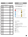
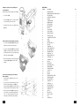
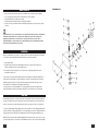
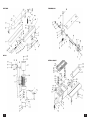
??? CARD
WARRANTY
1. KH Trading machines and tools are covered by 6/24 months warranty, starting on the date of
purchase, as described in the Civil Code (proof of purchase or invoice receipt must be
enclosed with the warranty card when making a claim).
2. This warranty does not cover defects caused by unprofessional handling, machine overloads, not
complying with instructions contained in this manual, using accessories that are not approved,
unauthorized repair, regular wear and tear and damages occurred during transport. Further, this
warranty does not cover parts and accessories such as the motor, carbon brushes, seals and
hot-air operated parts and parts that need to be changed regularly.
3. If the repair is to be found as not covered by the warranty policy, all costs including the repair and shipping to and from the repair centre will be paid by the customer, according to valid price list. See www.
4. When making a claim, you must present the warranty card, showing the date of the purchase, the
serial number of the machine, vendor stamp and signature of sales clerk, as well as the proof of
purchase receipt.
5. Warranty claim shall be made at the vendor shop where you bought your machine or you may mail
it to a service centre. The vendor is obligated to fill out the warranty card (date of sale, serial
number, vendor stamp and signature). All these information must be filled in at the time of sale.
6. The warranty period will be extended for the period of time for which the machine has been in the
service centre possession. If the repair or defect is not covered by the warranty policy, all costs including
the repair and shipping will be paid by the owner of the machine / tool. We recommend sending the
machine in its original packaging. Please, also enclose brief description of the defect with the packaging.
7. Before sending the machine for repair, clean it thoroughly. If the received machine is dirty, it may
be rejected by the service shop or you may be charged a cleaning fee.
USER'S MANUAL
OSCILLATING BELT
GRINDING MACHINE SB-108
SERVICE
Logistic centre Klecany
Topolová 483
250 67 Klecany
Czech Republic
Claim department phone number: 266 190 156
266 190 111
Fax:
260 190 100
http://www.KHnet.cz
Email: [email protected]
Product:
Type:
T-mobile: 603 414 975
O2:
601 218 255
Vodafone: 608 227 255
OSCILLATING BELT GRINDING MACHINE SB-108
Serial number (product series):
SB108
Date of manufacture:
Repair centre notes:
Date of sale, stamp, signature:
SB108
Without the correctly filled warranty card or without proof of purchase receipt, including
the product type (invoice, purchase receipt) no warranty claim will be processed.
Dear customer. Thank you for purchasing equipment from KH Trading, s.r.o.
Our company is ready to serve you - before, during and after you have purchased our product. If you have any
question, comment or idea, please contact our business centre. We will do our best to address your comment
or question in timely manner.
The first use of this device is understood as a legal step, with which the user confirms at his
own free will, that he has thoroughly read this manual and fully understands its meaning and
is fully aware of all the risks involved during use.
WARNING!Do not try to use this machine before reading this entire manual and before you know
how to handle it. Keep this manual for future reference.
Pay special attention to safety instructions.Not complying with safety rules may cause injury to the
operating person or to people standing by or it may cause damage to the machine or to the work
piece.
Pay special attention to safety notes and safety labels on the machine.
Do not remove or damage them.
To make future communications easier, write down
the invoice number or the sales contract number here.
DESCRIPTION
Machine description
This oscillating belt grinder is equipped with massive frame and may be used for wood grinding or similar
types of materials. The positioning mechanism enables you to work in vertical or horizontal positions. The main
supporting pedestal is made of cast iron and you may adjust its height. The side table is designed for curved
surface grinding. The sawdust vacuum system may be connected to piping with 100 mm in diameter.
The oscillating motion lowers the clogging of the grinding belt and increases the quality of the grinded surface.
Number of persons required to operate this machine: 1
TECHNICAL SPECIFICATIONS
Voltage . . . . . . . . . . . . . . . . . . . . . . . . . . . . . . . . . . . . . . . . . . . . . . . . . . . . . . . . . . .~230 V/50 Hz
Current . . . . . . . . . . . . . . . . . . . . . . . . . . . . . . . . . . . . . . . . . . . . . . . . . . . . . . . . . . . . . . . . . . .10 A
Input . . . . . . . . . . . . . . . . . . . . . . . . . . . . . . . . . . . . . . . . . . . . . . . . . . . . . . . . . . . . . . . . . . .1,5 kW
Grinding belt dimensions . . . . . . . . . . . . . . . . . . . . . . . . . . . . . . . . . . . . .152 × 2 743 mm (6" × 108")
Grinding belt speed . . . . . . . . . . . . . . . . . . . . . . . . . . . . . . . . . . . . . . . . . . . . . . . . . . . . . . .13 m.s-1
Main table dimensions . . . . . . . . . . . . . . . . . . . . . . . . . . . . . . . . . . . . . . . . . . . . . . . .900 × 305 mm
Side table dimensions . . . . . . . . . . . . . . . . . . . . . . . . . . . . . . . . . . . . . . . . . . . . . . . .290 × 255 mm
Sawdust vacuum piping diameter . . . . . . . . . . . . . . . . . . . . . . . . . . . . . . . . . . . . . . . . . . . .∅ 100 mm
Gross weight . . . . . . . . . . . . . . . . . . . . . . . . . . . . . . . . . . . . . . . . . . . . . . . . . . . . . . . . . . . . .280 kg
The accuracy of instructions, graphs and information contained herein, depends on the printing date. Due to
continuous product improvement, the manufacturer reserves the right to change technical parameters of the
product, without prior customer notification.
2
REPAIR AND MAINTENANCE REPORT
Report and maintenance report:
DATE
REPAIR AND MAINTENANCE REPORT
SERVICE SHOP
REVISION REPORT
???
SAFETY PRECAUTIONS
The user is obligated to perform tests and revisions of electrical equipment of the machine
in accordance with valid rules and regulations. Result report:
DATE
REVISION REPORT
REVISION TECHNICIAN
Number / SIGNATURE
• This device may be used by a qualified person, 18 years or older who has been
trained in work and environmental safety procedures.
We recommend placing warning labels on conspicuous places around your workplace.
• "Prevent injuries" - WOODWORKING MACHINES.
Safety symbols and self-adhesive safety stickers:
Do not use water or foaming fire extinguishers
Caution. Electrical equipment
Use face protective shield
Read manual before use
Use ear protection
Harmful or irritating substances
Use respiratory passageways protection
Danger of having fingers cut
Place the self-adhesive stickers on appropriate and visible spots on your machine.
Symbols used in this manual
Warning!
Danger of bodily injuries or severe material damages.
Caution! You are using electrically powered machine!
Electrical hazard.
Risk of being caught by moving machine parts!
Beware of moving machine parts. Loose clothing or body parts may get caught by
moving machine parts.
Caution!
Danger of damages!
Note:
Additional information.
Use personal protective gear.
3
•
•
•
•
•
•
•
•
•
•
•
•
•
•
•
•
•
•
•
•
•
•
•
•
•
•
•
•
•
•
•
•
•
General
Plastic bags and packaging materials pose danger for small children and animals.
Make sure you know your tool or machine and that you are familiar with its operating procedure. Know the
hazards if not used correctly.
Person using this machine must know how to safely operate this equipment, must be properly trained and
familiar with hazards and risk that may occur during use of this machine.
Pay special attention to safety notes and safety labels. Do not remove or damage them. If the warning
label becomes unreadable or damaged please, contact your vendor.
Maintain your working area clean. Disorganized and dirty working area may cause accidents.
Never work in narrow or poorly lit rooms. Make sure that the floor is stable and that your work may be
done comfortably. Always keep stable posture.
Observe your work continuously and use all your senses during work. Do not continue to work if you
cannot pay full attention.
Maintain your tools clean.
Handles must be kept free of grease and dirt.
Make sure no children, unauthorized persons or animals have access to your workshop.
Never put your hands or legs inside the working area.
Never leave your machine unattended during operation.
Use only for purposes for which it has been designed.
Use personal protective gear such as safety goggles, ear protection, respirator, safe working shoes etc.
Do not underestimate your abilities and know your limits. Use both hands.
Never work under the influence of alcohol or other drugs.
Do not use the device if you feel dizzy or weak.
Any modifications or improvements to the machine are strictly prohibited. DO NOT USE if you discover
bent part, crack or other damage.
Never perform any maintenance while the device is in use.
If you see any unusual sign or hear any strange sound, stop the device immediately and stop working.
Do not forget to remove all wrenches and screwdrivers from you machine after use.
Before use, make sure that all screws are tightened securely.
Perform maintenance regularly. Before use make sure the machine is in good working conditions
and without any damage.
Use only original spare parts during repairs.
Using non-original spare parts or other parts not approved by the manufacturer may cause injury to the
operating personnel.
Use suitable tool or machine for particular type of work. Use this machine only for work that is capable of handling. Do not overload tools, accessories or the machine. For large work volume use more powerful machine.
Do not overload your machine. Measure the work load in such way, so it could be done with comfortable
speed. Damages due to machine overload are not covered by waranty.
Do not expose to extremely high temperatures or direct sunlight.
This machine is not design for use in humid environments or under water.
if you are not using your machine, store it in a dry and safe place, out of reach of children.
Before turning your device on, make sure that all safety elements are working properly and effectively.
Make sure all moving parts are in good condition.
Before use make sure that no part is cracked or stuck. Make sure all parts are attached and assembled as designed. Beware of all other conditions that may have a negative effect on the proper functioning of your machine.
If not stated otherwise in this manual, all damaged parts must be repaired or changed.
4
PEDESTAL
Position
1
2
3
4
5
6
7
8
Description
PEDESTAL
SCREW M4 × 10
FLAT WASHER 4
FUSE
SPECIAL WASHER
WASHER
SUPPLY CABLE PROTECTIVE COVER
PLASTIC NUT
TRANSMISSION 2
Position
Description
1
TRANSMISSION PLATFORM
2
SCREW WITH NUT M8×20
3
TURBINE ROD
4
BALL BEARING 6202
5
RING
6
OIL SEAL WITH HOLE
7
WASHER
8
TOOTHED GEAR
9
TOOTHED WHEEL SHAFT
10
WEDGE
11
TRANSMISSION PLATFORM
12
SCREW M6 × 20
13
NUT M8
14
SAFETY WASHER 8
15
FLAT WASHER 8
16
TRANSMISSION HOUSING
17
OIL SEAL
Pcs
1
4
2
1
2
1
4
5
Pcs
1
4
1
4
4
2
1
1
1
1
1
4
4
4
4
1
1
21
28
29
30
31
32
33
34
35
36
37
38
39
40
41
42
43
44
RULER
Position
1
2
3
4
5
6
7
8
9
10
11
12
13
14
15
16
17
18
19
ADJUSTING PLATFORM
DEFLECTIVE SHAFT
BALL BEARING 6201
CLOSED NUT M10
NUT M6
BEVELLED SEAL MEASURING GAUGE
DIAL WITH SCALE
LABEL
SCREW M6 × 30
ANGLE RULER
FLAT WASHER ∅8
HANDLE
FLAT WASHER ∅5
SCREW M5× 15
EXPANDABLE COVER
EXPANDABLE COVER
SET
PLATFORM III
Description
STUD 2 × 16
SELF-CUTTING SCREW
M3×15
BEVELLED EDGE LEDGE
SELF-CUTTING SCREW M3.5 x12
RIGHT RULER COVER
ALUMINIUM ALOY
RULER
LEFT RULER COVER
SUPPORTING SCREW WITH NUT M6×35
BEVELLED EDGE MEASURING GAUGE
FLAT WASHER 8
PLASTIC HANDLE
KNOB WITH INNER THREAD M6
DIAL
REVERSE IMPACT PIN
SELF-CUTTING SCREW
SUPPORTING COLUMN
BEVELLED PRISM
FLAT WASHER 4
CLOSED SCREW M4×6
1
8
8
8
4
4
1
1
4
1
2
2
19
19
1
4
4
Pcs
1
1
1
2
1
1
1
2
1
1
1
2
1
1
1
1
2
2
2
Additioal safety rules regarding oscillating belt grinders
• Do not work on machine that is not completely assembled and installed in accordance with the
instructions contained in this manual.
• Your machine has been designed only for grinding wooden surfaces and work pieces. If you attempt to
grind different materials, you are risking fire or work piece damages.
• Always use eye protection.
• Machine is designed only for indoor use.
• Make sure machine is installed on even and flat surface. If you are using machine installed improperly,
you may damage the electric motor.
• If you work with long and heavy pieces the machine may tip over or move from its installation place. Make sure
the machine is securely fastened to the floor.
• Before starting your work, make sure that the belt is moving in the correct direction that is along the arrow
located on the back of the belt.
• Make sure that the grinding belt is properly aligned on the guiding rollers.
• Inspect the belt for correct tension and damages.
• Always hold the work piece strongly during work.
• Always use stopper if the arm of the grinder is in the horizontal position.
• If you are using the wheel part of the machine, always grind on its lower side and make sure that the work
piece is securely fastened on the worktable. If you attempt to use the upper side of the wheel the work
piece may get thrown away.
• Make sure to maintain the maximum gap of 1.6 mm between the table or the stopper and the grinding
wheel or belt.
• Do not wear working gloves during work. Do not hold the work piece using a piece of cloth.
• Perform the grinding along the wood fibre pattern.
• Do not attempt to grind too small pieces that may not be securely fastened.
• Try to avoid grinding in positions where your hands may slip from the work piece and touch the grinding
wheel or belt.
• If you are working on a large piece of wood, use auxiliary support stand with the same height as the
height of the worktable.
• Do not try to grind work piece that is not properly supported and fastened. Support it with the bevelling
ruler, stopper or worktable. The only exception that applies to grinding of a work piece with difficult shape
is the use of outer grinding cylinder.
• Before switching your machine on, remove all stoppers, sawdust or small cut-offs from the worktable.
• If the machine is running, never perform setting changes, assembly or adjusting operations.
• Before assembly or disassembly, always disconnect the main supply cable form the wall outlet.
• When you finish your work, lock your machine with padlock to prevent use by unauthorized persons or
children. Store the key in safe place, away from children and unauthorized persons.
•
•
•
•
•
20
Electrical equipment
Observe all basic safety rules when using electrical equipment to prevent risk of fire, injuries by electrical
shock and other hazards. Before using this machine, read this manual entirely and follow all safety instructions.
Make sure the power cable plug is plugged into the correct wall outlet.
The voltage in the wall outlet must be the same as shown on the specification label to prevent overheating
or damage to the electric motor. Too low voltage will not provide your machine with enough power.
Before connecting the machine to the wall outlet make sure that the main switch is in the "OFF" position.
When you finished your work, disconnect the power plug from the wall outlet and switch off the main switch.
When disconnecting the plug from the wall outlet, never pull the cable by its cord.
5
• Protect the power cable from high temperatures, oils, paint thinners and make sure that the cable is not
hanging over sharp edges.
• Inspect the power cable regularly. If damaged have it replaced by qualified technician. Inspect extension
cables regularly. If damaged, have it replaced.
• If you need to use an extension cable, use cable with appropriate power rating. Use only completely
unwound. Inspect extension cables regularly. Damaged cables must be repair immediately.
• Before performing any maintenance, repair or adjustment, switch off the main switch and disconnect the
power cable from the wall outlet.
• Make sure no one may switch you machine incidentally on. Do not keep your fingers close to the main
switch, unless absolutely necessary.
• Do not use in environments where explosives are stored or used (paint shops, warehouse with flammables etc.).
• Do not use in humid environments or if wet.
Fire prevention
During work do not smoke or use open fire.
ASSEMBLY
• Before throwing the packaging material out, make sure no part is left inside. If so, take it out and install it.
Use the part listing for check-up and the installation drawing for guidance.
Connecting your machine to the power source/wall outlet
• Machine must be connected to a separate electrical loop. This loop must be rated for minimum current
load of 10 A and must be equipped with 10 A fuse.
• Damaged or worn out supply cable must be repaired or changed immediately by qualified electrician.
• Before connecting your machine to the power source make sure that the main switch is in the OFF
position. Make sure the electrical parameters of the source comply with the requirements shown on the
specification label. All wirings must have solid contact. Using your machine with low voltage may damage
the electric motor.
Grounding your machine
WARNING: YOUR MACHINE MUST BE PROPERLY GROUNDED TO PREVENT
ELECTRICAL SHOCK INJURIES TO THE OPERATING PERSON.
• Make sure that the machine is switched on for the first time by qualified electrician only.
• In case of machine breakdown, make sure that the machine is properly grounded to prevent injuries from
electrical shock.
• Your machine is equipped with a supply cable with a plug and grounding pin. The plug may only be
connected to a wall outlet properly installed in accordance with local rules and regulations.
• Do not try to modify the supplied plug. If the plug cannot be connected to your wall outlet, have qualified
electrician perform the applicable modification of the plug.
• Incorrect connection of the grounding pin poses great risk of injuries by electrical shock. The grounding
wire is green with yellow stripes or without. If you need to change or repair the supply cable or its plug do
not do so under live current.
• If you are not sure how to connect your machine or do not understand any of the rules and regulations
regarding the connection of the grounding wire, wall outlet or other electrical parts, have qualified
electrician to perform the entire operation.
6
11
12
13
14
15
16
17
18
19
20
21
22
23
24
SCREW M8x15
SAFETY WASHER ∅ 8
TURBINE BOX
TURBINE ROD
JOINT
PLATFORM
SCREW M8 × 20
ADJUSTING SCREW
SHAFT
LARGE WASHER
SCREW WITH NUT M6×12
SHAFT
HAND WHEEL
WASHER
ADJUSTING PLATFORM
SETTING CONSOLE
Position
Description
1
TABLE
2
SUPPORTING PLATFORM
3
SUPPORT
4
SCREW M8 × 12
5
SETTING CONSOLE
6
NUT M10
7
SAFETY WASHER ∅ 10
8
FLAT WASHER 10
9
SCREW WITH NUT M10X20
10
SWITCH
11
SCREW M5× 8
12
SUPPLY CABEL
13
REVOLVING SHAFT
14
REVOLVING CONSOLE
15
SAFETY WASHER ∅ 8
16
SCREW M8 × 20
17
SCREW M8 × 12
18
POSITIONING SHAFT SEAL
19
C-RING
20
SAFETY NUT
21
HANDLE
22
HANDLE M10
23
COPPER WASHER
24
SPECIAL NUT M18
25
NUT M8
26
SETTING SCREW M8 x20
27
HANDLE
4
4
1
1
1
1
3
1
1
1
1
1
1
1
Pcs
1
2
2
6
1
6
6
6
6
1
2
1
2
2
8
8
6
2
4
2
2
2
2
2
6
6
2
19
MOTOR
Position
1
2
3
4
5
6
7
8
9
10
11
12
13
14
15
16
17
18
19
20
21
22
23
24
25
26
27
28
Description
TRANSMISSION COVER
HANDLE
SETTING SCREW M6×15
SCREW M6 × 15
FLAT WASHER ∅ 6
SCREW WITH NUT M8×20
FLAT WASHER ∅ 8
TRANSMISSION MOUNTING TABLE
PLATFORM
UNIVERSAL COUPLING
SETTING SCREW M8 x8
UNIVERSAL COUPLING WASHER
UNIVERSAL COUPLING
SCREW WITH NUT M10x25
SAFETY WASHER ∅ 10
MOTOR PLATFORM
MOTOR CONSOLE
PLATFORM
SCREW M6 × 40
SCREW M8 × 25
SPECIAL NUT M12
FLAT WASHER ∅ 12
GREASE BOX
PRESS BALL
BEARING 51101
PRESS SHAFT
NUT M16×1,5
SAFETY WASHER ∅ 16
DRIVING CYLINDER
MOTOR
TRANSMISSION 1
Position
Description
1
HANDLE
2
NUT M8
3
WEDGE 5×5×20
4
WEDGE 8×7
5
SCREW M4 × 10
6
PLATFORM
7
SCREW M6 × 15
8
CLUTCH
9
TOOTHED GEAR
10
SHAFT
18
Pcs
1
1
2
4
4
2
2
1
1
2
1
1
4
4
2
1
1
2
1
1
1
2
2
1
1
1
1
1
• Use only 3 wire extension cables with a grounded 3-pin plug.The 3-pin wall outlet must be fully
compatible with the 3-pin plug.
• Damaged or worn out cable must be repaired or changed immediately.
OPERATION
Before switching your machine on, turn on the sawdust vacuuming system.
Recommended suction speed 20 m.s-1.
Setting the height of the main table
• Release the two setting handles (A) and (B)
on the left side.
• Turn the turn-handle on the front side of the
table up and set the required height.
• Tighten the two setting handles (A) and (B)
to secure the table position.
Changing the grinding belt
• Loosen the two screws on the upper side of the
table cover (C) and open it. Lift the lever (D) to
release the grinding belt (E). Change the old
belt for a new one. Press on the lever (D) to
tension the grinding belt.
Pcs
1
1
1
1
6
2
7
2
1
1
7
Setting the position of the grinding belt fine adjustment.
(When the belt is still in the middle of the worktable).
• Loosen the nut (F).
• Turn the nut (G) clockwise or counter clockwise
to set the desired position of the belt.
• If the track of the belt is correct, tighten the nut
(F) again.
Vertical and horizontal grinding operations
• Loosen the handles (A) and (B) under the main
table and move them to the back position.
• Loosen the setting handle (H) and by turning the
table (I) set the desired angle. Observe the dial
during turning. When you set the required angle,
tighten the setting handle (H).
• Move the main table to the side table and tighten
the handles (A) and (B) to ensure the table
stability.
Observe the following procedure during
shape grinding
• Open the table cover (J) and secure it in the
open position.
• Loosen the three screws with the inner notches.
Remove the guiding cylinder cover (K) and
place the grinding shaft (L) on its place. Tighten
the three screws M5×15 with the inner notches.
• Place the rubber cylinder (M) on its place and
secure it with one screw with hexagonal head
6,35 × 12,7 mm and a washer. Now you may
start using your machine for shape grinding.
8
BELT TABLE
Position
1
2
3
4
5
6
7
8
9
10
11
12
13
14
15
16
17
18
19
20
21
22
23
24
25
26
27
28
29
30
31
32
33
34
35
36
37
38
39
40
41
42
43
44
45
46
47
48
Description
GRINDING TABLE
GRINDING TABLE FASTENING DEVICE
FLAT WASHER 8
SCREW WITH NUT M8×12
HANDLE
OUTER WASHER
INNER WASHER
ROTATING SEAL
BALL BEARING
NUT M14
LONG SCREW
SHORT SCREW
GRAPHITE PAPER
SPECIAL NUT M6
CONNECTING PLATFORM
SHAFT
SPRING
FLAT WASHER ∅ 16
NUT M16
SCREW M8 × 25
SAFETY WASHER ∅ 8
FLAT WASHER ∅ 8
FASTENING SHAFT
SCREW M6 × 25
LARGE WASHER ∅ 8
SCREW M8 × 12
SCREW M6 × 20
NUT M12
HANDLE ROD
HANDLE KNOB M12
GRINDING BELT
SEALING WASHER
COLLECTOR
NUT M8
HANDLE
GRINDING TABLE COVER
SEALING WASHER
FLAT WASHER ∅ 6
SCREW M6 × 10
SCREW M6 × 8
FLAT WASHER ∅ 6
SEALING WASHER
SCREW M5× 20
NUT M5
END SWITCH
SWITCH COVER
DIAL
SCREW M5× 8
Pcs
1
1
2
2
1
1
1
1
2
5
1
1
1
2
1
1
1
1
1
4
4
4
2
1
1
1
1
1
1
1
1
1
1
2
2
1
1
4
4
4
4
1
2
2
1
1
1
1
17
Installing the sawdust vacuum outlet
• Mount the outlet in place with four screws 6,35 × 6,35 mm with half-circle head. See the following
instructions.
PART LIST
U-TABLE
Position
1
2
3
4
5
6
7
8
9
10
11
12
13
14
15
16
17
18
19
20
21
22
23
24
25
26
27
28
29
30
31
32
33
34
35
Description
SCREW M8 × 15
WASHER
PAPER FOR CYLINDRICAL GRINDING ∅ 38
RUBBER CYLINDER ∅ 38
GRINDING CYLINDER SHAFT
ROD
GUIDING CYLINDER COVER
SCREW M6 × 15
RING ∅ 25
BALL BEARING 6205
GUIDING CYLINDER
GUIDING CYLINDER SHAFT
GREASE BOX
SCREW M6 × 45
GUIDING CYLINDER CONSOLE
SCREW M8 × 25
HANDLE
SCREW M5× 8
FLAT WASHER ∅ 5
U-BLOCK I
U-TABLE SPINDLE
WEDGE
SCREW M4 × 10
SCREW M10 × 20
U-BLOCK II
U-TABLE
U WASHER TYPE III
U WASHER TYPE II
U WASHER TYPE I
U WASHER TYPE IV
PAPER FOR CYLINDRICAL GRINDING ∅ 50
PAPER FOR CYLINDRICAL GRINDING ∅ 76
RUBBER CYLINDER ∅ 50
RUBBER CYLINDER ∅ 76
SETTING SCREW M5x10
Pcs
1
2
1
1
1
1
1
3
1
2
1
1
2
1
1
1
1
6
6
1
1
1
3
1
1
1
1
1
1
1
1
1
1
1
3
TROUBLE-SHOOTING
WARNING: Before performing repair always disconnect the main supply cable from the
wall outlet.
DEFECT
PROBABLE CAUSE
REMEDY
The motor is not working
•
Defective or broken main switch
ON/OFF.
•
•
Damaged or defective supply
cable.
Switch relay is damaged or not
working correctly.
Burned electrical motor.
Burned fuse.
•
•
•
•
The speed (revolutions) of the belt
are slowing down during work
•
The operating person is pressing on the work piece too hard.
•
Do not press on the work piece
so hard during work.
The grinding belt is leaving its track
during work
•
Incorrectly set belt track.
•
•
Set the correct belt track.
See chapter Changing,
tensioning and belt adjustment
The wood is getting burned during
the grinding process
•
The grinding belt or wheel is
clogged with the resin from the
wood.
Too hard pressure on the work
piece.
•
Change the belt or grinding
wheel.
Lower the pressure on the work
piece.
•
16
•
Remove and change all
damaged parts before switching
your machine on.
Have qualified electrician
perform all electrical repairs.
Each attempt to repair the
electrical motor is dangerous.
Repair must be done by
qualified electrician only.
•
9
MAINTENANCE
???
•
•
•
•
•
TRANSMISSION 2
Keep your device clean. Dirt may enter the inner mechanism of your machine and cause damage.
Do not use aggressive cleaning solution or paint thinners to clean the machine.
Clean plastic parts with cloth dipped in soup water.
Clean and lubricate metal surfaces with a cloth dipped in paraffin oil.
If you are not using your machine, lubricate it with suitable grease and store it in a dry place to prevent
corrosion.
Detailed description of use of this machine is not included in this manual, because the manufacturer /
distributor assumes that the user is experienced in similar type of work. Also according to the
applicable law, this machine is considered as a commonly sold and used tool. If the user is
unfamiliar with the use of this machine, we recommend finding out more information about using
this machine at the Department of work safety.
DISPOSAL
When the operational life of your device is over, dispose off it in accordance with valid rules and regulations.
Your product is made of metal and plastic parts that may be recycled when separated.
1. Disassemble all parts.
2. Separate all parts according to the material they are made of (e.g. metals, rubber, plastics, etc.).
Take the separated parts to the recycling facility near you.
3. Electrical waste (used electrical power tools, electric motors, recharging equipment, electronics,
accumulators, batteries etc.).
Dear customer. In accordance with the valid regional rules and regulations describing the management of
electrical waste, electrical waste is considered dangerous. Disposal of electrical waste must be therefore
handled as dangerous waste in accordance with waste management rules valid in the state you are in.
It is prohibited to mix electrical waste with regular household waste.
You may return your used electrical appliance to a recycling facility near you. More information about
electrical and dangerous waste disposal may be obtained from your local authority or from the Internet.
CAUTION
If the machine breaks down, send it back to the vendor for quick repair. Please, enclose brief description of
the defect. That makes repair easier. If the machine is still covered by warranty, enclose the warranty card
and proof of purchase receipt. After the warranty period expires, we repair your device for a special price.
To prevent possible damages during shipping, pack the device carefully or use the original packaging material. We are not liable for shipping damages due to incorrect packaging of your device. If making a claim at the
shipping company the level and method of packaging plays a major role during claim evaluation process.
Note: Pictures and contents in this manual may slightly differ form the actual product or accessories. It is due
to continuous improvement of our products. Such small differences have no effect on the product functionality.
10
15
RULER
DETAILED PART DRAWING
U-TABLE
PEDESTAL
14
11
BELT TABLE
TRANSMISSION 1
MOTOR
SETTING CONSOLE
12
13