1
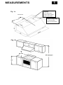
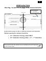
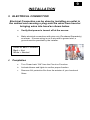
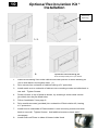
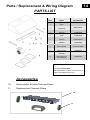
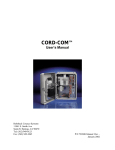
User’s Manual Under Cabinet Series VEHOOD3610 NOTE: PLEASE INSPECT HOOD IMMEDIATELY UPON RECEIVING. CLAIM OF DAMAGE AFTER 7 DAYS OF DELIVERY WILL BE DENIED. This unit is designed for indoor residential use only. DO NOT USE OVER A WOOD GRILL OR MOUNT IN OUTDOOR ENVIRONMENT. Please read this manual thoroughly before installing your range hood. Store it in a safe location for when you need to reference it in the future. TABLE OF CONTENTS 1 SAFETY INFORMATION ........................................................................ 2-3 CONTENT CHECKLIST ............................................................................. 4 MEASUREMENTS .................................................................................. 5 PREPARATION ............................................................................... 6 – 7 INSTALLATION ................................................................................ 8 – 9 RE-CIRCULATING KIT (OPTION) INSTALLATION .......................................... 10 OPERATION & FEATURES ..................................................................... 11 CLEANING & MAINTENANCE ................................................................. 12 TROUBLESHOOTING ............................................................................ 13 PARTS LIST / REPLACEMENT ................................................................. 14 WIRING DIAGRAM ............................................................................. 15 WARRANTY / CONTACT US ............................................................. 16-17 Verona Hood VEHOOD3610 can be installed using outside venting or by use of a re-circulating kit. HOOD SPECIFICATIONS 36” W x 10” H x 22” D 600 CFM Hood construction - 430 Stainless Steel 120V 60Hz 3.0 A 2 SAFETY INFORMATION SAFETY INFORMATION TO REDUCE THE RISK OF A FIRE, ELECTRICAL SHOCK, AND/OR INJURY OBSERVE THE FOLLOWING: Unit is intended for indoor residential use only. If you should have questions, contact the manufacturer at the address or telephone number listed in the warranty. In case the unit should need to be cleaned or repaired, switch power off at service panel and lock service disconnecting means to prevent power from being switched on accidentally. When the service disconnecting means cannot be locked, securely fasten a prominent warning device, such as a tag, to the service panel. Installation work and electrical wiring must be done by a qualified technician in accordance with all applicable codes and standards, including fire-rated construction. Sufficient air is needed for proper combustion and exhausting of gases through the flue (chimney) of fuel burning equipment to prevent back drafting. Follow the heating equipment manufacturer’s guideline and safety standards such as those published by the National Fire Protection Association (NFPA), and the American Society of Heating, Refrigeration and Air Conditioning Engineers (ASHRAE), and the local code authorities. Because the unit is made of stainless steel, it may contain sharp edges. Be careful to avoid cuts and abrasions by wearing protective gloves during installation and cleaning. Before you begin to cut or drill into the wall, verify that there is no electrical wiring or any other hidden electrical components. Ducted fans must always be vented to the outdoors. The unit must be properly grounded and installed at the recommended height before beginning operation. To reduce the risk of fire, use only metal ductwork. CAUTION: FOR GENERAL VENTILATING USE ONLY. DO NOT USE TO EXHAUST HAZARDOUS OR EXPLOSIVE MATERIALS AND VAPORS SAFETY INFORMATION 3 TO REDUCE THE RISK OF FIRE, OR ELECTRIC SHOCK, DO NOT USE THIS FAN WITH ANY SOLID-STATE SPEED CONTROL DEVICE. Regardless of heat level, never leave any surface materials unattended while operating an open flame. Always turn hood ON when cooking at high heat. Depending on amount of usage, clean ventilating fans and filters frequently. Grease should not be allowed to accumulate on fan or filter. For instructions on the how to clean, see maintenance page. Never leave surface units unattended at high settings. Boil-overs may cause smoking and greasy spillovers may ignite as result. Heat oils slowly on low or medium settings. Use proper pan size. Always use cookware appropriate for the size of the surface element. TO REDUCE THE RISK OF INJURY TO PERSONS IN THE EVENT OF A RANGE TOP GREASE FIRE, OBSERVE THE FOLLOWING: SMOTHER FLAMES with a close-fitting lid, cookie sheet, or metal tray, then turn off the burner. BE CAREFUL TO PREVENT BURNS. If the flames do not go out immediately, EVACUATE AND CALL 911. NEVER PICK UP A FLAMING PAN - Doing so may result in serious burns and possibly spread the fire. DO NOT USE WATER – Grease fire must be extinguished before further action may be taken. Using water will agitate the grease and may cause a violent steam explosion. Use a Fire Extinguisher ONLY if: You know you have a Class ABC extinguisher, and you already know how to operate it. The fire is small and contained in the area where it started. The fire department is being called. You are able to safely control the fire with your back to an open exit. * Based on “Kitchen Fire safety Tips” published by NFPA. 4 CONTENT CHECKLIST 1. CONTENTS INCLUDED a. (1) VEHOOD3610 - 36” hood assembly b. (1) User’s manual c. (1) Black 6” collar & (1) 6” – 7” Transition d. (3) Mesh filters e. (1) Screw packet 2. CONTENTS NOT INCLUDED a. Recirculation Kit (Purchased separately) b. 6” or 7” Metal ducting 3. TOOLS REQUIRED (NOT INCLUDED) a. Safety gloves b. Safety glasses c. Electric drill w/ starter bit d. Utility knife e. Spirit level f. Measuring tape g. Writing instrument (pen, marker, pencil) h. Aluminum or duct tape i. Wire nuts Round metal duct, length to suit installation. MEASUREMENTS Fig. 1a Centerline 5 Keyhole 2 ¼” from Rear 16 ⅝” from Center 10 ⅜” from Rear Electrical Opening 1 ⅞” from Rear 13 ⅝” from Center 17 ⅞” 24”-36” 6 PREPARATION 1. BEFORE YOU START **DO NOT INSTALL IF DAMAGED** **RETURN OR EXCHANGE WILL BE DENIED IF INSTALLED** a. Confirm you have all parts and required tools for this installation. b. Installation may take at least 2 to 3 hours from start to finish. c. Minimize the number of duct elbows (turns) used to maximize hood performance d. Duct elbows should be no closer than 12” to each other, further apart if possible. e. At least two people are needed for installation. f. Hiring a certified installer and electrician is recommended. g. In some jurisdictions, make-up / replacement air is required. Check with your local building codes for more details. 2. LOCATION a. Determine the exact location you want to install the range hood. b. A centerline should be located on bottom of cabinet or soffit. c. Distance between cooktop and range hood should be between 24”- 36”. (Fig. 1b) d. Range hood should be mounted at stated measurements to ensure performance and lifespan of electrical components. e. For cabinets with recessed-bottom, securely fasten wood strips on bottom sides of the cabinet so that it is level, and can receive and support the screws which hold the hood. 7 PREPARATION Use Fig. 1a and 1b on page 5 for measurements Center Line Electrical Opening 1 ⅞” from Rear 13 ⅜” from Centerline Install wood strips to level if cabinet bottoms are recessed. Cabinet opening for exhaust should be: 6½” diameter if using collar ONLY 8¼” diameter if using collar + 6” – 7” transition Place hood under the cabinet to be installed and mark 4 keyholes to drill starter hole. 8 INSTALLATION 1. UNDER CABINET OR SOFFIT INSTALLATION a. Make sure all preparation steps are completed. b. Connect 6” black collar to hood. (1) Using screws provided c. If using transition, connect transition with damper to 6” black collar, wider part to front (2) d. Secure collar and transition with sheetmetal screws and/or duct tape for an air-tight seal. Do not impede damper movement. (3) e. Cutout hole for 6” or 7” diameter duct exhaust hole in cabinet or soffit, per figure 1C. Recommended attaching 6” collar & 7” transition (with damper) to hood before setting into place. f. Drill Wiring Access hole in cabinet per figure 1C. (If not using a plug), feed the wires coming down into top of the hood through the opening in the bottom of the cabinet. (For recirculation kit installation, you must feed wires through recirculation vent before going into hood) g. Using the screws provided, fasten 4 hood screws into cabinet or soffit at location identified. DO NOT SCREW IN ALL THE WAY, LEAVE 1/8” OF SCREW SHOWING. h. Lift the hood up to the cabinet, such that the screws protrude through the key holes on hood top. Push hood back flush against the wall, so that screws support hood. i. While holding hood, tighten all 4 screws securely from under the hood. j. NOTE: Install additional screws through the back or top for security. 2. CONNECT DUCTWORK a. 1. 2. Connect 6” or 7” metal duct to collar or transition. Your METAL Exterior Exhaust Outlet (Purchased Separately), installed at the end of your duct run on the roof or outer wall of your home must include an integrated damper to block the intrusion of outside air into the home. 3. 9 INSTALLATION 3. ELECTRICAL CONNECTION Electrical Connection can be done by installing an outlet in the cabinet and securing a plug onto the wires from hood or bringing wires into hood as shown below. a. Verify that power is turned off at the source. b. Make electrical connections with wire nuts (Purchased Separately) as shown. If house wiring is not 2-wire with a ground wire, a ground must be provided by the installer. Green or Bare = Ground Black = Hot White = Neutral 4. Completion a. Turn Power back “ON” from the Circuit or Fuse box. b. Activate blower and lights to confirm proper function. c. Remove ALL protective film from the exterior of your hood and filters. 10 Optional Recirculation Kit * Installation Electrical Opening 1-3. 6. 4. Optional Recirculating Kit Purchased Separately from your Dealer 1. Place Recircutating Vent under cabinet and mark position of holes allowing for unit to slide back in the keyhole slots. (1) 2. Drive screws into underside of cabinet leaving a ⅛” protrusion. 3. Install metal vent to underside of cabinet onto mounting screws and slide back to rear wall. Tighten Screws. 4. Fasten diverter to top of hood as shown, by screwing 4 sheet metal screws (provided) into the pre-dilled holes. 5. Follow “Installation” from page 8 6. Drive machine screws (provided) into underside of Recirculation Kit, leaving a ⅛” protrusion. 7. Install hood to underside of Recirculation Lit onto mounting screws and slide back to rear wall. Tighten Screws. Add additioal screws to back wall if neccessary 8. Install Charcoal Filters to sides of blower inside Hood 11 OPERATION & FEATURES 1. EASY ACCESS CONTROL SWITCH (from left to right) 0 Button 0 – Fan Off 1 Button 1 – Low 2 Button 2 – Medium 3 Button 3 – High Light On/Off Control 0 1 2 3 2. MESH FILTERS a. (3) 10-3/4” x 15” Dishwasher Safe Aluminum Mesh filters 3. PUTTING IN THE MESH FILTERS a. Insert the Filter into the unit at an angle. (Fig. 3b) b. Push the Mesh filter upward(Fig. 3c) c. Snap into place(Fig. 3c) Fig. 3b Fig. 3c 12 CLEANING & MAINTENANCE WARNING!!! To prevent the possibility of a fire and explosion, do not use flammable liquids or solvents to clean the unit or any of its parts. Check to make sure all power sources are disconnected before servicing or taking unit apart for cleaning. Please thoroughly clean the unit weekly 1. RANGE HOOD a. Use household cleaner to remove grease or dirt from the outer shell of the unit. Spray on wiping cloth or sponge and wipe in the direction of the grain to avoid scratching the unit. (DO NOT SPRAY DIRECTLY ONTO UNIT) b. Stainless steel cleaners can help keep your rangehood bright and clean. 2. MESH FILTERS a. Clean the Mesh filters regularly for the most efficient suction power. b. Let it soak thoroughly in warm soapy water overnight, wipe with sponge and rinse. c. OR Mesh filters may be cleaned using residential dishwasher. TROUBLESHOOTING 13 TROUBLESHOOTING WARNING!!! Check to make sure all power sources are disconnected before starting any troubleshooting. Safety gloves and glasses should be worn when working on the unit. Serious injury or death may occur if safety precautions are not followed. VEHOOD3610 Series LED Light Issue 1. LED lights may need to be changed. Contact EuroChef or replacement bulb. Unit Lacks Power 1. Confirm that circuit breaker is “ON” 2. All wiring is connected. Unit making humming noise 1. Replace defective capacitor with new one. Fan Blower Fails Call for Service 14 Parts / Replacement & Wiring Diagram PARTS LIST Item Name Part Number 1 Spacer 2 Lamp Panel 3 LED Lamp C1-0403-0306 4 Switch C1-0405-0303 5 Capacitor C1-0401-A250-22 6 LED Driver C1-0402-D001 7 Motor / Blower C1-0302-A110-06A B101-7236-09 B101-7236-06 8 Aluminum Filter C1-0604-0107 10 Recirculating Kit (Optional) RK36 11 Charcoal Filters for Recirculating Kit C1-0603-0303 How to Order Parts Contact Eurochef USA: 866-844-6466 or submit a service call at www.veronaappliances.com Accessories 10. Recirculation kit with Charcoal Filters 11. Replacement Charcoal Filters 10 11 Parts / Replacement & Wiring Diagram 15 WARRANTY / CONTACT US 16 LIMITED WARRANTY Verona Hoods warrants its product against defects in material or workmanship as follows: Labor: For a period of one (1) year from the date of purchase, if the product is determined to be defective, Verona will attempt to repair the product, at its option, at no charge. After the warranty period, customer must pay for all labor charges. During the "labor" warranty period there will be no charge for any work done on the purchased model. (All labor repairs are limited only to the installation of electrical components.) Parts: In addition, Verona will supply, at no charge, new or rebuilt replacements in exchange for defective parts for a period of one (1) year. After the warranty period, customer must pay for all parts. During the "parts" warranty period, there will be no charge for parts You must provide the serial number of your unit for any replacement parts during the warranty period. This warranty applies to products purchased and serviced in the United States only. * Verona will attempt to repair malfunctioning units prior to shipping a replacement. In the case that a unit cannot be repaired and must be replaced, Verona will not be held liable for removal or installation fees of the malfunctioning and replacement unit. 17 WARRANTY / CONTACT US WHAT IS NOT COVERED BY MANUFACTURER WARRANTY 1. Damages resulting from any of the following: a. Improper installation or maintenance b. Any repair, modification, alteration or adjustment not authorized by the manufacturer or an authorized service dealer c. Misuse and/or accidents d. Incorrect electric current, voltage or power supply e. Improper setting of any control (Pressing multiple selections at the same time) f. Improper chemical cleaning (commercial or industrial cleaning agents) 2. Products purchased for use in a commercial or industrial setting (such as in a hotel, office, restaurant, or other business) 3. Damage resulting from natural disasters (earthquake, flood, storm, etc.) 4. Aluminum Filters, Charcoal Filters and Light Bulbs CONTACT US Verona 41 Mercedes Way, Suite 25 Edgewood, NY 11717 TEL: (866) 844 - 6566 FAX: (631) 254 - 3426 E-mail: [email protected] Information subject to change without notice