1
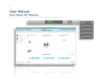
iRC & iRC(b) User Manual Table of Contents
Chapter 1
About iRC Measure.............................................................................. 5
1.1
About This User Manual........................................................................................6
1.2
iRC vs. iRC(b) - What Is The Difference?...............................................................6
Chapter 2
2.1
Chapter 3
3.1
Quick Guide.......................................................................................... 9
iRC Measure Tutorial..............................................................................................9
Step-By-Step Guide.............................................................................11
Software Installation............................................................................................ 11
3.1.1Activation.................................................................................................................................... 11
3.2
Equipment setup.................................................................................................. 11
3.3
Using the iRC Measure application....................................................................12
3.3.1
Sound system setup .................................................................................................................14
3.3.2
Microphone configuration.........................................................................................................14
3.3.3
Output & levels ..........................................................................................................................15
3.3.4Measurements ...........................................................................................................................16
3.3.5
3.4
3.4.1
Chapter 4
Filter design................................................................................................................................18
Using the Amarra with iRC(b) & Symphony with iRC applications.................21
Filter selection........................................................................................................................... 21
Understanding more.......................................................................... 23
4.1
Impulse response.................................................................................................23
4.2
Magnitude response............................................................................................23
4.3
Mixed-phase filters..............................................................................................23
Page 2
4.4
Target curve design guidelines...........................................................................24
4.5
Loudspeakers in rooms.......................................................................................25
4.5.1
Loudspeaker placement........................................................................................................... 25
4.5.2
Sweet spot and dispersion....................................................................................................... 25
4.5.3
Reflections – Good and bad .................................................................................................... 26
4.5.4
Useful tips.................................................................................................................................. 26
4.6
Recommended reading............................................................................................................ 27
Chapter 5
5.1
Troubleshooting.................................................................................. 28
Troubleshooting the iRC Measure application..................................................28
5.1.1
Sound system setup problems................................................................................................ 28
5.1.2
Playback problems...................................................................................................................... 2
5.1.3
Measurement problems........................................................................................................... 29
5.1.4
Filter design problems.............................................................................................................. 30
5.2
Troubleshooting the Sonic Studio iRC Filter Bank window..............................31
5.2.1
Account login or authorization problems............................................................................... 31
5.2.2
Playback problems.................................................................................................................... 31
Chapter 6
6.1
Appendix A.......................................................................................... 32
Operational Information......................................................................................32
6.1.1
Measurement Sample Rate...................................................................................................... 32
6.1.2
Saving iRC Measure Projects................................................................................................... 32
6.1.3
Saving Filter Files Created in iRC Measure............................................................................. 32
6.1.4
Mic Recommendations............................................................................................................. 32
Page 3
Page 4
About This Manual
This manual, as well as the software described in it, is furnished under license and may only be used or copied in accordance with
the terms of such license. The information in this manual is furnished for informational use only, is subject to change without notice,
and should not be construed as a commitment by Sonic Studio, LLC. Sonic Studio, LLC assumes no responsibility or liability for any
errors or inaccuracies that may appear in this book.
Except as permitted by such license, no part of this publication may be reproduced, stored in a retrieval system, or transmitted, in
any form or by any means, electronic, mechanical, recording, or otherwise, without the prior written permission of Sonic Studio,
LLC.
Notice of Liability
The author and publisher have made every effort to ensure the accuracy of the information herein. However, the information
contained in this document is provided without warranty, either express or implied. Neither the authors, Sonic Studio, LLC, nor its
dealers or distributors will be held liable for any damages to be caused either directly or indirectly by the instructions contained in
this book, or by the software or hardware products described herein.
SONIC STUDIO, LLC MAKES NO WARRANTIES, EXPRESS OR IMPLIED, INCLUDING WITHOUT LIMITATION THE IMPLIED
WARRANTIES OF MERCHANTABILITY AND FITNESS FOR A PARTICULAR PURPOSE, REGARDING THE APPLE SOFTWARE. SONIC
STUDIO, LLC DOES NOT WARRANT, GUARANTEE, OR MAKE ANY REPRESENTATIONS REGARDING THE USE OR THE RESULTS OF
THE USE OF THE SONIC STUDIO, LLC SOFTWARE
IN TERMS OF ITS CORRECTNESS, ACCURACY, RELIABILITY, CURRENTNESS, OR OTHERWISE.THE ENTIRE RISK AS TO THE RESULTS
AND PERFORMANCE OF THE SONIC STUDIO SOFTWARE IS ASSUMED BY YOU. THE EXCLUSION OF IMPLIED WARRANTIES IS
NOT PERMITTED BY SOME STATES. THE ABOVE EXCLUSION MAY NOT APPLY TO YOU. IN NO EVENT WILL SONIC STUDIO, LLC,
ITS DIRECTORS, OFFICERS, EMPLOYEES, OR AGENTS BE LIABLE TO YOU FOR ANY CONSEQUENTIAL, INCIDENTAL, OR INDIRECT
DAMAGES (INCLUDING DAMAGES FOR LOSS OF BUSINESS PROFITS, BUSINESS INTERRUPTION, LOSS OF BUSINESS INFORMATION, AND THE LIKE) ARISING OUT OF THE USE OR INABILITY TO USE THE SONIC STUDIO SOFTWARE EVEN IF SONIC STUDIO
HAS BEEN ADVISED OF THE POSSIBILITY OF SUCH DAM- AGES. BECAUSE SOME STATES DO NOT ALLOW THE EXCLUSION OR
LIMITATION OF LIABILITY FOR CONSEQUENTIAL OR INCIDENTAL DAMAGES,THE ABOVE LIMITATIONS MAY NOT APPLY TO YOU.
Notice of Rights
Copyright © 2014 Sonic Studio, LLC and Dirac Research AB. All rights reserved.
No part of this document may be reproduced, stored in a retrieval system or transmitted in any form or by any means, without the
prior written permission of the publisher.
Sonic Studio, Amarra, Amarra Hifi, Amarra Symphony, iRC, iRC(b) iRC Measure and the Sonic Studio and Amarra logos are
trademarks of Sonic Studio, LLC. All other company or product names are either trademarks or registered trade- marks of their
respective owners. All features and specifications described within this manual are subject to change. Sonic Studio and Dirac
Research AB makes no warranty of any kind regarding the accuracy, correctness, or sufficiency of the information in this document.
However, we will make every reasonable effort to keep the document accurate, correct, and sufficient in response to your feedback.
Page 5
Chapter 1.................................................About iRC Measure
The listening room is usually the weakest link of any sound system. Loudspeakers have been designed for a certain placement
in a room, but in an imperfect environment performance suffers and it’s impossible get the full benefit from your speaker
investment. Imaging, clarity, and bass tightness are all affected by the limitations imposed by your listening room, and the result
is that your listening experience can be significantly diminished.
Amarra with iRC(b) and Amarra Symphony with iRC combines our industry defining music player with leading-edge room
correction technology to optimize the sound of your system to its’ best possible performance.
The ‘iRC Measure’ app with Amarra Symphony and option for Amarra measures the acoustic characteristics of your loudspeakers
within the listening environment and then optimizes for timing, phase and frequency anomalies imposed by your room. The
result is massively improved imaging and sound staging because now your room will be working with your sound system, not
against it.
iRC integrates premium mixed-phase room correction technology from Swedish technology leader, Dirac SE. Dirac room
correction technology is used in cinemas, studios, as well as the world’s most famous luxury car brands including BMW, Bentley
and Rolls Royce to bring sound into harmony with the listening space. Amarra iRC is very different from standard room correction
technologies that rely on simple minimum-phase EQ technology. Amarra iRC optimizes not only the frequency response but
also the impulse response at the listening position, which is a critical factor for accurate staging, clarity and bass reproduction.
You’ll be amazed.
iRC will:
•
Improve the imaging of your sound system
•
Improve the clarity of your music
•
Produce a tighter bass
•Reduce listening fatigue
•
Improve the timbre
•
Remove resonances and room modes
•
Reduce early reflections
Page 6
1.1
About This User Manual
This user manual is divided into multiple sections. It describes the use of Sonic Studio’s
• ‘iRC Filter Bank’ and ‘iRC Measure.app’ in Amarra Symphony
• ‘iRC(b) Filter Bank’ and ‘iRC(b) Measure.app’ options for Amarra
Unless otherwise noted, features and workflow discussed in this manual apply to all of the above.
1.2
iRC vs. iRC(b) - What Is The Difference?
The main difference between iRC and iRC(b) is in the Measure application:
• The ‘iRC Measure.app’ in Amarra Symphony is full spectrum. It processes frequencies from 15 Hz-20 kHz+
The iRC Measure app’s Filter Design Tab. Note the wide frequency correction spectrum
Page 7
• The ‘iRC(b) Measure.app’ option for Amarra is designed for lo-mid range and bass management. It is limited to processing
frequencies from 15 Hz-500 Hz
The iRC(b) Measure app’s Filter Design Tab.
The Quick guide in the next section lists the main steps to get started with iRC Measure. More detailed instructions are provided
in the Step-by-step guide starting on page 12, and thereafter divided into four sections about Software Installation, Equipment
setup, and Using the, respectively. Additionally, there is a section on Understanding more section beginning on page 24,
followed by a Troubleshooting section on page 29.
If you are reading this document as a PDF file on a computer, then you should be able to click on the underlined links in the text
to jump to the referenced section. The same applies for the entries in the Table of Contents.
Page 8
Useful remarks are preceded by this lamp symbol.
Warnings and important remarks are preceded by this caution sign.
Page 9
Chapter 2............................................................. Quick Guide
The following steps will get you started immediately. In the Step-by-step guide on page 12, the process is described in more
detail.
1.
Run the Amarra or Amarra Symphony Installer. License iRC or iRC(b) for use. (See page 12) Note that you can run
iRC or iRC(b) on two Macs at the same time.
2.
Set up your measurement mic. Measure @ 48k sample rate. Use a microphone stand. Holding the mic in your hand
is not recommended.
3.
Connect the audio output of your computer or your DAC to the input of your sound system (on your amplifier/
preamplifier). (page 8)
4.
Start the iRC Measure application (page 13) Make sure that Amarra or Amarra Symphony is not running.
5. Follow the on-screen instructions to select your microphone input and microphone calibration file (page 15),
audio outputs (page 15), measure (page 17) and optimize (page 19) your sound system.
6.
When you have saved your filters from the iRC Measure application, start Amarra or Amarra Symphony application.
(page 22)
7.
Click on the iRC button on the Amarra or Amarra Symphony interface, and click on an empty filter slot (numbered
1-4) then select your newly created filter. (page 22)
8.
Enjoy a more musical and accurate reproduction of your favorite music!
Page 10
2.1
iRC Measure Tutorial
The iRC Measure tutorial gives you step-by-step instructions on microphone set-up, measuring your room and creating filter
files for use in Amarra or Amarra Symphony.
View the iRC Measure Tutorial
Page 11
Chapter 3................................................Step-By-Step Guide
This guide will go through each step in more detail to achieve the best possible sound.
Need more thorough explanations? Refer to Understanding more, on page 24, where some important concepts
are discussed.
If you have any problems with the Amarra iRC or the iRC Measure application, then some possible solutions are
addressed in the Troubleshooting section beginning on page 29.
3.1Software Installation
Run the Amarra or Amarra Symphony installer (.mpkg file) and follow the on-screen instructions. iRC Measure is installed in the
Amarra or Amarra Symphony Application Folder.
3.1.1
Activation
After installation is completed, in order for you to run iRC Measure, you will
first need to activate the iRC feature in Amarra or Amarra Symphony. When
clicking on the iRC button in Amarra for the first time, you will be prompted with
an Authentication window to enter your user license information delivered at
the time of purchase.
Once iRC has been authorized in Amarra or Amarra Symphony, iRC Measure
for your app will also be licensed.
Note that the computer has to be connected to the Internet and any active
firewalls have to allow HTTP (normal Internet access).
3.2
Equipment setup
1.
Connect the output of your DAC or Mac’s line output to your amplifier or preamplifier input.
Page 12
2.
Make sure your DAC is powered on.
3.
Connect your microphone and verify operation in System Preferences/Sound tab
a.
If you are using a USB microphone, just connect it to a USB port on the computer. Make sure to use 48 kHz
sample rate for measuring.
b.
Otherwise, connect the microphone to your Mac’s sound input or external microphone pre-amp and analogto-digital converter (“A/D Converter”). Make sure to use 48 kHz sample rate for measuring.
Some microphones require 48V phantom power. Be sure to follow the microphone usage instructions.
Avoid microphone feedback! If your A/D Converter has a direct monitor function, this must be turned off. Some
A/D Converters have a physical volume knob for direct monitor, in this case it has to be turned down to zero level.
Some professional A/D Converters have signal modifiers like compression or equalization. Double check that any
such signal modifiers are turned off.
4.
Before continuing, please close all other audio applications on your computer.
5.
Start the iRC Measure application to begin measuring your room.
Make sure the main volume control on your pre-amp or amplifier is turned down prior to playing any test signals
from iRC Measure. You can adjust to normal volume after testing output levels in iRC Measure.
3.3
Using the iRC Measure application
Launch iRC Measure by clicking on the Icon for your product inside the Amarra or Amarra Symphony Application folder.
Page 13
If you own Amarra Symphony,
Launch iRC Measure
If you own Amarra and have purchased the iRC(b) option, launch
iRC(b) Measure
IMPORTANT NOTE REGARDING MEASUREMENT SAMPLE RATE: If possible, make all measurements at
48 kHz. Amarra’s iRC Filter Bank automatically interpolates the filter files for all sample rates, so there is no need
to make measurements for each sample rate available on your DAC.
The iRC Measure application measures the acoustical properties of your sound system and designs customized Amarra iRC
filters including impulse response correction for your room and loudspeakers.
To apply the resulting Amarra iRC filters to music, you will have load your saved filter set into Amarra or Amarra
Symphony’s iRC window (see page 22).
• Please note that your computer must be connected to the Internet during the measurements or during the filter
optimization. If the computer is not connected during the measurements, then certain parts of the optimization will be
delayed until a connection is available. To save time, it is recommended having a connection during the whole process.
Any active firewalls have to allow HTTP.
The workflow is logically divided into a number of tabs at the left side of the window and these are meant to be worked through
sequentially from the top down.
You’ll find step-by-step instructions along the right side of the iRC Measure application window. The content changes with the
active workflow tab. Simply click the tab to open and click to close.
Page 14
3.3.1
Sound system setup
This is the first tab in the iRC Measure application
1.System configuration in the “Choose system
configuration” drop-down box (A). Please note that for
iRC Measure, the system configuration is preset for stereo
and cannot be changed.
2.
Select the device that you want to use for playback
in the “Test signal playback device” drop-down box (B).
Use the same device and channel assignment that will be used for listening.
If a device is grayed out in the drop-down box, it may mean that it is being used by another application. In this
case, please close all other audio applications and press the “Rescan” button (C). Clicking the “Rescan” button
also searches for DACs or other devices that may have been added after starting the iRC Measure application.
Continue to the next tab by clicking the “Proceed” button in the lower right corner or by clicking the tab itself.
3.3.2Microphone configuration
This is the second tab in the iRC Measure application
1.
In the “Recording Device” drop-down box (F), select
the device that your microphone is connected to.
2. In the “Recording Channel” drop-down box (G),
select the input channel number that your microphone is
connected to.
If a device shows two (or more) numbered channels,
then usually “1” corresponds to Left and “2” to Right.
Page 15
3.
You may optionally load a microphone calibration file by clicking the “Load file” button (H).
Only the most expensive measurement microphones can be expected to have transparent recording characteristics. All other
microphones can benefit from a calibration file to restore transparency.
The microphone calibration file is a text file that should contain the microphone magnitude response. The file format which is
supported by iRC Measure application consists of lines of <frequency, level> pairs, where the level is given in decibels (dB).
Some calibration files instead specify the calibration adjustment for each frequency. Find out if your file has this format, and if
so, then switch the signs on the level numbers to modify it to the supported format.
Continue to the next tab by clicking the “Proceed” button in the lower right corner or by clicking the tab itself.
3.3.3
Output & levels
This is the third tab in the iRC Measure application
In order to get an accurate measurement of the sound system,
some initial adjustments of the playback and recording levels
are required. Start by placing the microphone inside the
listening area.
1.
For each loudspeaker channel, select the output
channel that it is connected to using the corresponding
“Output channel” drop-down box (J).
Use the same device and channel assignment that will be
used later for listening. If the assignments don’t match with
the Amarra or Amarra Symphony player output, then filters may be applied to the wrong channels or audio output may even be
muted.
Click the play button for the test noise in the selected output channel by pressing the Test button (K).
Page 16
To protect your ears and equipment: Turn down the volume on your sound system before pressing the play
button for the first time and then slowly turn up the volume.
See the section on Playback problems on page 30 for problem solutions.
Tip: You can use the space bar of your keyboard to trigger the test button for the selected output channel.
Tip: you can use the arrow keys on your keyboard to quickly both toggle between channels and adjust the volume
for each channel.
2.
Adjust the levels (M) for the recording to be within the green area on the level meter (L). Apply a three-step process
(see Measurement problems on page 30 for problem solutions):
I.
If possible, set the sound card output level to 0 dB (usually max). Depending on the DAC, there may be a
physical volume knob or a software level slider.
II.
On your amplifier, adjust the volume knob to a “normal” listening level. Not disturbingly loud, but not too low
either.
Adjust the gain of the microphone input in order to arrive within the green area on the level meter.
Continue to next tab by clicking the “Proceed” button in the lower right corner or by clicking the tab itself.
3.3.4Measurements
This is the fourth tab in the iRC Measure application
It is now time to built the acoustical model of your listening space by measuring the sound system in your room. The accuracy
of the model is very important for designing optimal room correction filters, so follow the tips below to get the best result. Now
would also be a good time to save and name your project before proceeding with the measurements. You can save the project
at any time by clicking the “Save…” button in the lower left corner.
• Always use a stage-type microphone stand similar to the On-Stage Stands MS7701B Euro Boom Microphone Stand to firmly
place the measurement microphone in the indicated positions. Do not hold the microphone in your hand during measurements
as this will likely cause handling noise and taint the measurements significantly.
Page 17
• Use a microphone stand with a boom arm
attachment. A boom arm allows you to vary the height
and placement of the microphone position within the
listening area, which is important to get an accurate
acoustical model.
• Minimize external noise such as talking, opening
or closing doors or windows, and playback of sounds
during the measurements. This is to avoid interruption
in the measurement process and corruption of
acoustical model data.
• Turn off any computer programs that may make any
noise, such as Skype or your email client.
• Turn off any audio effects such as “low-cut” EQ or
compression.
1.
Select the most suitable listening environment preset by clicking on the corresponding graphic (P). In general, it is
important to collect measurements in the most likely “listener’s head” positions (sitting, standing, leaning forward, etc.).
Avoid making measurements in a too small space. Even for the “Chair” listening environment, it is important to spread out the
microphone positions in a sphere of at least 1 meter of diameter. A too small a space will result in over-compensation that will
sound very dry and dull.
2.
Place the microphone in the indicated position (Q).
The first measurement should always be taken in the center of the listening region, in the desired “sweet spot”, as this will be
used for alignment of levels and delays between loudspeakers.
Direct the microphone upward, pointing to the ceiling, to get the most omnidirectional recording of the room response.
Switch the view selector (R) for each position to better localize the microphone positions. Carefully note the left and right
positioning of each measurement position in the separate view graphs.
3.
Press the Start button (S) to collect a set of measurements. This will play a sweep in each loudspeaker and one final
sweep in the first loudspeaker again.
If the measurement was successful, then the position indicator will move to the next spot. Repeat the procedure from step 2
above until nine (9) positions have been covered.
Page 18
If your microphone pre-amplifier has a clip indicator,
then keep an eye on the microphone input. If it clips
during measurement, then re-take that measurement.
(Usually, the clipping will be detected by the iRC
Measure application, but depending on level settings,
the clipping event may fail to be detected.)
If the measurement failed, then usually an error
message will be given. Follow the instructions in the
error message, or refer to the troubleshooting section
Measurement problems on page 30.
Tip: You can click each measurement point (T) to view
its recorded sequence in the graph (U). You can also
delete individual measurements by clicking the red X
(X) that appears when the measurement point is marked. Doing so will allow you to retake that individual measurement.
3.
After all nine positions have been measured, there is enough data to design a set of filters.
Using the microphone positions indicated by the iRC Measure application will generally give you consistent results. However,
the microphone positions are not required to be in exactly these positions; if your listening environment is unusual, then you
may use a different set of microphone positions.
Taking all measurements close to the sweet spot will generally not give optimum performance because the microphone positions
need some spread in order to acquire enough acoustical information about the room.
Don’t forget to save the project before proceeding.
Continue to the next tab by clicking the “Proceed” button in the lower right corner or by clicking the tab itself.
3.3.5
Filter design
This is the fifth and last tab in the iRC Measure application.
The filter design algorithm uses the measured data together with a target frequency response to calculate filters that optimize
the frequency response and the impulse response of the sound system. Finding the best target frequency response may require
a little experimenting from your side. After completing the measurements, the iRC Measure application will automatically
Page 19
generate a suggested target curve that matches the
measurements; however, you can alter the curve for
even better performance.
The filter design algorithm has a hard-coded maximum
gain value that limits the boost at any frequency.
1.
There are two ways to modify the frequency
response:
i.
Dragging the target frequency curve
at the anchor points (a).
ii. Dragging the frequency limits on
either side of the frequency range (b).
Refer to Target curve design guidelines on page 25
for advice on how to design a good target response.
The resulting filter will leave the audio signal unmodified in the shaded frequency regions. This can be useful if you, for example,
are perfectly happy with the high frequency performance, but want to address room resonances in the bass.
It is possible to add (or delete) anchor points by double clicking on the target curve (or on the points).
The zoom level is shown at the top of the graph (c).
To zoom in, draw a box around the area that you would like to zoom into.
To zoom back to the previous level, click on the minus sign next to the zoom level (c) or double-click in the graph.
To view the impulse response of the system, before and after correction, click on the “IMPULSE” button (i). In the impulse
response view, this button will change its label to “SPECTRUM” and clicking on it will take you back to the frequency view.
It is possible to set a target curve for all channels at once, a linked group of channels, or one channel at a time. Use the channel
tabs (d) on the right side of the plot area to change the grouping configuration.
i.
Clicking on the chain symbol of a channel tab (e) causes the channel to detach from the linked group and
showing the detached channel’s curve in the plot area. You can also drag and drop to unlink.
ii.
Dragging and dropping a detached channel tab onto a linked channel tab causes the detached channel to join
the group and show all the grouped channels’ curves in the plot area.
Page 20
2.
Press Optimize (f) to create a set of filters.
3.
When the optimization has completed (this may take some time depending on the
speed of your computer and how many sampling rates you selected to make filters for),
press “Save Filter” (g) below the target editor to save the filter to a file that you will be able
to open into the Amarra or Amarra Symphony iRC filter bank window.
To be able to load the filter in the Amarra or Amarra Symphony application, make sure to save it
in this directory:
~/Documents/Dirac/Filters
To design a new filter for the same sound system, repeat the procedure from step 1 above. To
design filters for a different sound system, then go back to the Sound system tab and follow the
instructions from Sound system on page 15.
Saving a project once a target curve has been set will save the state of the target curve in the
project.
If you are testing several target curves it may be a good idea to save each target with the Save
Target button (j). This will allow you to revisit and change the target curves from which a specific
filter has been generated by loading them with the Load Target button (l). Loading a target will
apply it to the currently visible channel (group).
Please note that there are two save buttons with different functions, one for saving the filter “Save Filter” (g) and one for saving
the project “Save…” (h).
Page 21
3.4
Using the Amarra with iRC(b) & Symphony with iRC applications
Amarra with iRC is an easy-to-use music player application. For this manual, the scope will be limited to the Sonic Studio iRC
Filter Bank window. For a more complete list of Amarra or Amarra Symphony with iRC functions, please refer to the Amarra or
Amarra Symphony User Manual located inside the Amarra or Amarra Symphony app folder.
To open the Sonic Studio iRC Filter Bank window, click the iRC button (a) in the Amarra window. That action opens the large iRC
Filter Bank window.
3.4.1
Filter selection
Filter sets created for the Sonic Studio iRC Filter Bank window by the iRC Measure application must
be loaded into an iRC processor slot.
The Sonic Studio iRC Filter Bank window has four (4) separate slots (c) where your filter files can
be loaded for quick selection. To load a filter set into an empty slot:
1.
Double-Click on an empty filter slot. This opens a Mac Finder dialog box where you can
navigate to the folder where you stored your Amarra iRC filter sets created with iRC Measure.
These are .filter files.
Select the filter set that you want to load, then select OK.
Listen to the result of applying the loaded filters:
1.
Play a track through Amarra or Amarra Symphony.
2.
Make sure that the “Filter” switch (b) on the Sonic Studio iRC Filter Bank window is set
to “On”. Click the switch to change it.
3.
Switch between loaded filters by clicking the corresponding filter slot (c). The active
filter slot has a blue indicator.
4.
Gain – Because the filters files you create in iRC Measure may cause the output to
overload, you may need to reduce the overall gain of a filter. Typing – (minus key) and
entering a numerical value, then enter, turns down the overall output gain of Amarra or
Amarra Symphony.
Page 22
You can see the output level of Amarra by clicking on the M button in Amarra Symphony and use it to accurately set the Gain.
We’ve prepared a special Pink Noise file at 0 vu level for you to calibrate the gain of each filter. This test file can be downloaded
here:
Download Gain Calibration File
Page 23
Chapter 4...............................................Understanding more
4.1
Impulse response
The impulse response measures how a transient such as a drum beat is reproduced in the room. Reflections, diffraction,
resonances, misaligned drivers, etc., combine to smear out the transient. As the name indicates, the impulse response shows
how the system and room responds to an impulse input signal. An ideal speaker adds no ringing, coloring, or time smearing to
the recording, so its impulse response should look just like the input impulse.
The similarity between the different loudspeakers’ impulse responses at the listening position affects the perception of stage
and image. The more similar the impulse responses, the more easy it is to trick the brain that the loudspeakers are not really
there, and that the sound emanates from a virtual stage spanned by the physical speakers.
The performance of Amarra iRC can be very successful in making your system response resemble that of an ideal speaker
due to the robust design of so-called mixed-phase filters. The result of applying Amarra iRC can be viewed in the iRC Measure
application, by clicking the IMPULSE button in the Filter Design tab.
4.2
Magnitude response
The magnitude response (or more commonly known by the imprecise term “frequency response”) measures how much each
frequency component, or tone, is attenuated. A good magnitude response should be as smooth as possible. Otherwise, different
tones are reproduced with unequal strength, and the music is subjected to undesired coloration.
4.3
Mixed-phase filters
Infinitely many different filters can be designed to have the exact same magnitude response. They differ only in their impulse
response. Therefore, it is useful to classify filters according to how their impulse responses behave.
Two commonly used filter classes in audio applications are minimum-phase filters and linear-phase filters. They are two special
cases that are relatively easy to design, but that come with tightly constrained impulse response characteristics. A minimumphase filter, by definition, is constrained to apply only the smallest possible delay to the signal given a desired magnitude
Page 24
response. A linear-phase filter, by definition, applies a delay that is constant across the whole frequency range. Therefore, neither
of these two filter designs can make a desired change to the phase or impulse response, unless the desired change is exactly the
particular change they make by definition. Minimum-phase and linear-phase filters may even worsen both the impulse response
and the magnitude response of a system, simply by applying their magnitude response corrections at the wrong time.
A more difficult design task is to make a mixed-phase filter that matches a desired magnitude response while also having
a customized impulse response. A properly designed mixed-phase filter can make significant improvements to the impulse
response of a sound system at the listening position:
• Misaligned drivers in multi-way loudspeakers can be corrected by automatically applying different delays to different
frequency ranges.
• Energy from direct wave and early reflections can be optimally combined to arrive as a single wave front to the listener.
Amarra iRC uses mixed-phase filters to optimize the impulse response while applying a desired magnitude response.
4.4
Target curve design guidelines
In the iRC Measure application, the desired magnitude response for each loudspeaker can be drawn manually. The reason for
providing this feature, instead of just optimizing for a flat magnitude response, is that different loudspeakers and different rooms
may require slightly different target curves for the best result.
Normally you want to have the same target curve for identical pairs of channels like the left and right front speakers. Therefore,
these are automatically grouped together by the iRC Measure application. Correcting for differences between the channels will
often give a substantial improvement in the stereo image.
The shaded regions in the target editor illustrate regions where the magnitude response will be left untouched. These regions
are adjustable by dragging in the handles on the shaded regions. Normally you want to correct the whole spectrum that is within
the frequency limits of the loudspeaker.
All loudspeakers tend to have a low frequency limit, below which the response is dropping rapidly. It is important to not boost
the bass too much under this low frequency limit, because it can easily overdrive the loudspeakers and lead to distortion. iRC
Measure application tries to identify the frequency where the response starts to drop and the automatically generated target
curve and correction frequency limits are adjusted accordingly.
If there is noise present during the measurements, this will often be visible in the measured frequency response as increasing
low frequency levels below the loudspeaker low frequency limit. This is not part of the loudspeaker response so this frequency
region is better left untouched.
Page 25
Some guidelines to adjusting the target curve are as follows:
Even small changes in the target magnitude response can give audible results. It is worthwhile to tweak the target in order to
address even the smallest nuance in the magnitude response.
Avoid sharp peaks in the target curve, as they may result in annoying tonal components in the frequency response. Generally
you want to have a smooth target curve.
A target curve that is slightly tilting down towards high frequencies (like the auto-target) is often preferable - a flat target often
sounds too bright. A loudspeaker with a flat on-axis response will usually have a slightly tilting in-room response. You can
experiment with the amount of tilt, especially in the treble region, to get a good tonal balance in your room.
If you have strong room-resonances in the low frequency region, completely eliminating these may make the sound thin in
comparison. You may want to apply a slightly increasing low-end below 100 Hz.
If you have dips in the magnitude response, sometimes it can sound better to not fill these in completely.
4.5
Loudspeakers in rooms
The topic of sound reproduction in small rooms, such as a living room as opposed to a concert hall, is huge. The room will define
how reproduced music is perceived. Roughly, the effect of the room on the sound can be divided into two parts - the effect on
frequency response (timbre, coloration) and the effect on spatial aspects of sound (spaciousness, envelopment, reverberation).
Both parts are affected by speaker placement and listener position.
4.5.1
Loudspeaker placement
Correct placement of the loudspeakers in your room is vital to get the best possible sound. Therefore it is often worthwhile to
experiment a bit with the loudspeaker placement. Always use the speaker manufacturer, acoustician or audiophile consultant’s
recommendations as a starting point.
4.5.2
Sweet spot and dispersion
The loudspeaker response varies with position in a room. The sweet spot is the region where the sound is perceived as best and
with very little variations. Outside of the sweet spot, the sound character deteriorates and is quite different from that within the
sweet spot.
Page 26
Room correction systems cannot extend the size of the sweet spot! The dispersion of the speaker cannot be changed, unless
several speakers are used together as a ”super speaker”. However, Amarra iRC can still improve the sound quality outside the
sweet spot.
4.5.3
Reflections – Good and bad
The sound that is radiated from the loudspeakers will be reflected by the walls of the room and eventually reach the listener at
different times and at different angles, depending on how many times the sound wave has been reflected off the walls.
Early reflections from angles close to the loudspeaker and diffraction reflections from the loudspeaker box itself are detrimental
to perceived sound quality and lead to undesirable coloration of the timbre of the sound.
Side reflections and late reflections are generally not as detrimental and can even help in improving perceived sound quality.
The reason for this difference lies in our hearing:
• In a reasonably sized room, we can tell a side reflection from a direct wave because of the time and direction differences
which our brain has learned naturally to separate. These reflections often contribute to a larger, more enveloping sound
stage. A small amount of reverberation is generally considered desirable in a room for sound reproduction. Amarra iRC
leaves the late reflections almost untouched. It only corrects for their spectral coloration.
•Early reflections and loudspeaker diffraction, which are very close in both time and angle to the direct wave, make the
sound more difficult for the brain to process properly. However, Amarra iRC corrects for these shortcomings by optimizing
the early arriving sound at the listener position.
At bass frequencies, room reflections may build up and create what is known as standing waves or room resonances. Characteristic
of these is that at certain frequencies, the bass is strong in some parts of the room and weak in other parts. Amarra iRC mitigates
the effect of standing waves inside the listening area.
4.5.4
Useful tips
Room acoustics is a complicated field but there are a few simple things that one can do to improve the listening experience.
Generally it is good to have quite much furniture on the walls and try to use soft furniture where possible. A large, thick rug on
the floor is good.
Many loudspeakers benefit from being moved out from the front wall a bit, and also to be placed at some distance from sidewalls. Experiment with toe-in: Many loudspeakers sound the best with the speakers pointing straight at the sweet spot or even
slightly in front of it. This helps to stabilize the stereo image when you are listening outside of the sweet spot.
Page 27
The listening location is important as well, having the sofa placed right up against the back wall is not ideal since there will be
very early reflections coming from behind and also the sound timbre changes a lot close to the walls.
4.6
Recommended reading
For the interested reader, a good book for learning more about how loudspeakers and rooms interact and how to achieve good
sound is “Sound Reproduction, Loudspeakers and Rooms” by Floyd E. Toole (2008).
Page 28
Chapter 5...................................................... Troubleshooting
If you run into any trouble, then please first refer to the common errors below.
If the problem remains, we would appreciate it if you would send us a description of the problem, perhaps including a supporting
screenshot, and also provide information of the Amarra iRC version, Mac model and OS version, and the DAC you’re using.
Submit a support request on http://www.sonicstudio.com/amarra/amarra_supportportal
5.1
5.1.1
Troubleshooting the iRC Measure application
Sound system setup problems
Problem
Possible Cause
DAC device does not show Cable disconnected
up in selection list
Power to DAC is OFF
Fix
Connect a suitable cable between the DAC and the computer.
Connect a power source and switch on
Driver not installed properly
If the problem persists, then refer to the manual of the DAC to
re-install the device driver software.
Error message: “Could Device is in use by other Close all other audio applications, press the “Rescan” button
in the “Sound System” tab, and try again.
not open recording device, application
make sure it is not in use…”
Two USB devices share the Try connecting one of the devices to a different USB port
managed by a different USB controller.
same USB controller
Page 29
5.1.2
Playback problems
Problem
Possible Cause
No sound from level test or Audio cable disconnected
measurement playback
Amplifier is OFF
Caution: To protect ears and
equipment, never switch on Wrong source
or connect devices at a high preamplifier
volume setting!
Volume too low
Fix
Connect audio cable to sound card output and to sound system
(pre)amplifier input
Switch on amplifier
selected
on On the preamplifier, select the source corresponding to the
input that the sound card has been connected to
Increase volume on
(a)Preamplifier
(b)
Measurement
sounds distorted
DAC
If this does not help, then reduce the volume to a reasonable
level before attempting any other fixes!
signal Preamplifier input is overloaded Decrease the sound card output volume
Loudspeakers are distorting
Decrease the playback volume
Page 30
5.1.3
Measurement problems
Problem
Possible Cause
Level test meter does not Microphone disconnected
react
Fix
Connect microphone to mic preamplifier and connect
microphone preamplifier to sound card or to computer.
Microphone needs phantom
Switch off sound playback power
while attempting to fix this
problem. Instead, clap your Microphone preamplifier is
hands or make some other OFF
sound to detect a reaction Volume too low
on the level meter.
Measurement does not Error message
complete successfully
Enable the 48 V phantom power on the microphone preamplifier
input. Depending on the microphone preamplifier, this could
be a physical button or a software setting.
5.1.4
Switch on microphone preamplifier
Follow instructions given in the error message.
Filter design problems
Problem
Possible Cause
Filter optimization does not Client is offline
complete
Firewall is blocking access
Fix
Connect the client computer to the web
Disable firewall or set it to allow HTTP traffic
Page 31
5.2
5.2.1
Troubleshooting the Sonic Studio iRC Filter Bank window
Account login or authorization problems
Problem
Validation server
accessible
5.2.2
is
Possible Cause
not Client is offline
Fix
Connect the client computer to the web
Firewall is blocking access
Disable firewall or set it to allow HTTP traffic
Playback problems
Problem
Sound is not clean
Possible Cause
Audio device driver
updating
Fix
needs Update your playback device driver to latest stable version
Sound is clipping or distorted
Sometimes, there may be new drivers that have issues
Reduce the Gain by 1 dB increments in the Sonic Studio iRC
window until clipping goes away. Use the Meters in Amarra
Symphony to verify levels.
Sound card has a sound effect Disable all sound card sound effects. This may either be a
enabled
physical setting on the sound card or a driver setting in the
operating system.
Output sounds unfiltered
Amarra or Amarra Symphony Click the iRC button and launch Amarra iRC
iRC processor is not running
“Filter” is set to “Off” in Amarra Open the Amarra or Amarra Symphony iRC Filter Bank and set
or Amarra Symphony iRC Filter “Filter” to “On”
Bank
Page 32
Chapter 6...............................................................Appendix A
6.1
Operational Information
6.1.1Measurement Sample Rate
If possible, make all measurements at 48 kHz. Amarra’s iRC processor automatically interpolates the filter files for all sample
rates, so there is no need to make measurements for each sample rate available on your DAC.
6.1.2Saving iRC Measure Projects
Save your iRC Measure Projects to Documents/Dirac/Projects for easy recall.
Backup your Project files! Projects can be moved between computers, so saving these files to a backup device or CD is a good
idea should your computer fail.
6.1.3
Saving Filter Files Created in iRC Measure
Save filter (.filter) made in iRC Measure to Documents/Dirac/Projects for easy recall.
Filter files cannot be exchanged between computers. Instead build new filters by opening the Project file your filter(s) was made
from on the other computer, optimize and resave new filter files.
6.1.4
Mic Recommendations
To use iRC Measure software you need an omnidirectional full-bandwidth measurement microphone. We recommend that the
frequency response is within ± 1 dB in the area of the speaker’s frequency response range.
If the frequency response is not within ± 1 dB within the speakers frequency response range, we recommend that you use a
calibration file. iRC Measure supports using a microphone calibration file, as long as it represents the frequency response of the
Page 33
microphone and not the inverted frequency response. If your microphone does not have a flat frequency response it will give
you false measurement information and you will have to consider this when setting your target curve.
NOTES ABOUT MICROPHONES:
• A live performance cardioid-patern vocal or instrument mic is not recommended for use with iRC Measure.
• Use 48 kHz as the sample rate for measuring your room with Sonic Studio’s iRC Measure app. 48 kHz is the default
setting for iRC Measure. The iRC Filter Bank in Amarra Symphony automatically interpolates all sample rates from the
48 kHz filter file. This eliminates the need for an individual filter file for each sample rate.
• Sonic Studio recommends an 8 hour burn-in time prior to using all USB-connected mics for measurement.
• USB mics usually include a 2 meter (6 foot) USB cable. You may need to purchase a longer cable for measurement use.
• Always use a stage-type microphone stand similar to the On-Stage Stands MS7701B Euro Boom Microphone Stand to
firmly place the measurement microphone in the indicated positions. Do not hold the microphone in your hand during
measurements as this will likely cause handling noise and taint the measurements significantly.
_______________________________________________________________________________________________________________
XTZ Audio has a cost-efficient USB-connected microphone kit that includes a the calibrated mic, USB pre-amplifier,
cables, clip, and storage case.
| Buy Now - Europe | Buy Now - USA |
Download the XTZ Mic Pro Calibration File
Note: the XTZ will work with both Dirac Live and iRC Measure.
_______________________________________________________________________________________________________________
The UMIK-1 is a ‘Plug & Play’ omni-directional USB microphone designed for acoustic measurement. This microphone
provides low noise and accurate results you can rely on. Forget about driver installation, OS compatibility and un-calibrated
mics. The Umik-1 is a USB Audio class 1 device automatically recognized by the Mac Operating System. After purchase,
you can download a calibration file specifically for your UMIK-1 ensuring an accurate measurement.
| Buy Now |
| How To Use The UMIK-1 With Amarra Symphony with iRC |
Page 34
- If you already have a microphone pre-amplifier, we recommend an individually calibrated Behringer ECM8000:
Information
• Click here to download the Behringer microphone calibration file
- For reference use we recommend the Earthworks M23: Information
_______________________________________________________________________________________________________________
Page 35
iRC & iRC(b) User Manual Index
Symbols
48 kHz 12, 13, 32, 33
A
acoustical 13, 16, 17, 18
Activation 11
algorithm 18, 19
amplifier 9, 11, 12, 16, 18, 29, 34
B
Behringer ECM8000 34
C
calculate 18
calibration file 9, 15, 32
configuration 14, 19
correction 5, 13, 16, 19, 24, 26
D
DAC 9, 11, 12, 13, 16, 28, 29, 32
device 14, 15, 28, 31, 32
Dirac 4, 5, 20, 32
E
Earthworks M23 34
effects 17, 31
EQ 5, 17
Page 36
F
filter 9, 10, 13, 18, 19, 20, 21, 23, 24, 32
Filter Bank 21, 31
filter design 18, 19
frequency 5, 15, 18, 19, 23, 24, 25, 32, 33
frequency limits 19, 24
I
impulse 5, 13, 18, 19, 23, 24
Installation 7, 11
Installer 9
iRC 4, 5, 13, 21
iRC(b) 4, 5, 13, 21
iRC Measure 4, 5, 7, 9, 10, 11, 12, 13, 14, 15, 16, 18, 21, 23, 24, 28, 32, 38
L
linear-phase 23, 24
linked channel tab 19
listening 5, 14, 15, 16, 17, 18, 23, 24, 26, 27
M
Magnitude response 23
measurement 9, 15, 16, 17, 18, 29, 32, 33
microphone 9, 10, 12, 14, 15, 16, 17, 18, 30, 32, 33, 34
minimum-phase 5, 23
Mixed-phase filters 23
O
omnidirectional 17, 32
optimization 13, 20, 30
Output channel 15
Page 37
P
phase 5, 23, 24
pre-amp 12
R
Recording 14
Recording Channel 14
Recording Device 14
Reflections 23, 26
S
Sample Rate 32
Skype 17
SPECTRUM 19
Sweet spot 25
T
target 18, 19, 20, 24, 25, 33
Target curve 19, 24
target frequency curve 19
timing 5
Troubleshooting 7, 11, 28, 31
Tutorial 10
U
UMIK-1 33
X
XTZ 33
Page 38
Z
zoom 19
©2014 Sonic Studio, LLC — All rights reserved. No part of this document may be reproduced, stored in a retrieval system or transmitted in an form or by any means,
without the prior written permission of the publisher. Sonic Studio, Amarra, iRC Measure and the Sonic Studio and Amarra logos are trademarks of Sonic Studio, LLC.
All other company or product names are either trademarks or registered trademarks of their respective owners.
iRC_and_iRC(b)_Measure_1.0.4_UserManual v02r09
Page 39