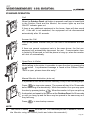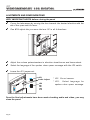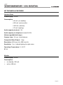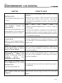
1
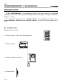
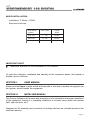
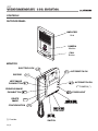
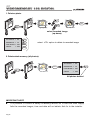
KIT
VIDEOMEMORY
VIDEOMEMORY 128
128 DIGITAL
DIGITAL
B/W DIGITAL VIDEOMEMORY 128 KIT Ref. 6115.
July 2003 Edition.
This technical document is edited by FERMAX ELECTRONICA S.A.E. for information
purposes. The Company reserves the right to modify any features of the products described
herein at any time and with no prior notification. Said changes will be reflected in subsequent
editions.
ENGLISH
Pag 28
KIT
VIDEOMEMORY
VIDEOMEMORY 128
128 DIGITAL
DIGITAL
INDEX
INTRODUCTION ............................................................................................. 30
SECTION I - USER MANUAL . ... .................................................................. 33
Controls ................................................................................................. 34
Video Door Entry System Operation .................................................... 35
SECTION II - INSTALLER MANUAL ............................................................. 41
Check before installing Kit .................................................................... 42
Power Supply Installation ..................................................................... 43
Outdoor Panel Installation .................................................................... 43
Monitor Mounting .................................................................................. 44
Monitor Programming ........................................................................... 45
Adjustments and Configurations ........................................................... 46
Kit Technical Features .......................................................................... 47
Outdoor Panel Internal Wiring Diagram ................................................ 48
Kit Wiring Diagram ............................................................................... 49
Auxiliary Devices Wiring Diagram ........................................................ 50
Troubleshooting Table ........................................................................... 52
COD. 94924 V07/03
Pag 29
KIT
VIDEOMEMORY
VIDEOMEMORY 128
128 DIGITAL
DIGITAL
INTRODUCTION
El KIT VIDEOMEMORY is an advanced Video Door entry system for simplified
installations (no call wires) specially designed to be installed in single residential
houses or villas.
It is basically composed of an Outdoor Panel, to be installed outdoors and a
Citymax Memory Monitor to be installed indoors, and which stores images up to
128.
KIT COMPOSITION:
Equipments included:
HIGH PERFORMANCE
MULTIPLEXED DIGITAL SYSTEM
- A Video Outdoor Panel with embeding box
STOP
+ - + -
- A Power Supply
POWER SUPPLY
- A Monitor with its connector.
HIGH RESOLUTION
FLAT MONITOR
1
2
- An Electriclock
Pag 30
KIT
VIDEOMEMORY
VIDEOMEMORY 128
128 DIGITAL
DIGITAL
BASIC INSTALLATION:
Installation: 3 Wires + COAX.
Required sections:
DISTANCE
(meters)
SECTION
COAX
RG59
up to 100
1
mm
2
100 to 150
1,5 mm
2
75 Ohm
150 to 200
2
mm
2
75 Ohm
75 Ohm
IMPORTANT NOTE
9
Maximum distance in this installation is 200 metres.
To make the utilisation, installation and handling of this equipment easier, this manual is
divided into two Sections:
SECTION I:
USER MANUAL
Shows how the Users, in other words all those who in one way or another are going to use
the system, should handle the equipment.
SECTION II:
INSTALLER MANUAL
This Section indicates all the steps and precautions to be followed for the proper installation
of the equipment, leaving it in operating conditions in its basic setup (make and answer
calls, open the door, etc.).
Diagrams for Kit assembly and connection of auxiliary devices are included as well as the
technical features.
Pag 31
KIT
VIDEOMEMORY
VIDEOMEMORY 128
128 DIGITAL
DIGITAL
Pag 32
KIT
VIDEOMEMORY
VIDEOMEMORY 128
128 DIGITAL
DIGITAL
SECTION I
USER MANUAL
Controls ................................................................................................. 34
Video Door Entry System Operation .................................................... 35
Pag 33
KIT
VIDEOMEMORY
VIDEOMEMORY 128
128 DIGITAL
DIGITAL
CONTROLS
OUTDOOR PANEL
AMPLIFIER
Grid
CAMERA
Module
HIG
H
CC RESO
D C LU
AM TIO
ERA N
PAANN
& TI
LLT
CALL
Button
MONITOR
ELECTRIC LOCK
1
RECORD
AUTOSWITCH ON
REC
NEXT IMAGE
PUSHBUTTON
FP
N
TIO
LU
SO
R
H RE NITO
HIG
MO
AT
FL
1
2
AUTOSWITCH ON
2
2nd CAMERA (*)
PREVIOUS IMAGE
PUSHBUTTON
DELETE
IMAGE
RP
STAIRS LIGHT
DEL
CONFIGURATION
BRIGHTNESS
TIME
CONTRAST
(*) If exists
Pag 34
OFF ON
SWITCH
KIT
VIDEOMEMORY
VIDEOMEMORY 128
128 DIGITAL
DIGITAL
VIDEO DOOR ENTRY SYSTEM OPERATION
MEMORY OPERATION
MEMORY OPERATION
The Video Memory 128 stores the last 128 images captured by the camera after calls are
made. These pictures can be browsed and viewed afterwards, with the time and date when
they were made.
Month
Year
Day
03/04/22
Time
Total Picture amount
12:45:37
028
The monitor can work in any of the modes represented below, that can be selected by
means of the memory operation pushbuttons.
TIME mode: to adjust the internal time and date.
Pressing «TIME» during 4 seconds and release, (with Monitor screen deactivated).
Year Month Day Time
ON
LUTI
RESO ITOR
HIGH MON
FLAT
TIME SET: 00/ /
1
2
: :
TIME
FP
+
FP
+....+
FP
TIME SET: 03/ /
Blinking
Confirm
Up
FP
TIME SET: 03/ /
: :
TIME
: :
FP
TIME SET: 03/05/
: :
TIME
TIME SET: 03/05/
: :
RP
RP
Down
FP
TIME SET: 03/05/22
: :
TIME
TIME SET: 03/05/22
: :
RP
TIME SET: 03/05/22 23: :
FP
TIME SET: 03/05/22 23: :
FP
TIME SET:03/05/22 23:37:
RP
TIME
TIME
TIME SET:03/05/22 23:37:
RP
Pag 35
KIT
VIDEOMEMORY
VIDEOMEMORY 128
128 DIGITAL
DIGITAL
TIME SET:03/05/22 23:37:11
TIME
FP
Up
RP
Down
TIME
Confirm
STAND BY mode: The monitor is always in this mode waiting for a call.
The monitor will take a photo automatically after a call is made and another one two
seconds later. If the monitor is in different modes when the call is made, the monitor will not
take photos.
TION
OLU
RES ITOR
HIGH MON
FLAT
+
1
2
1st Photo 2 seconds
2nd Photo
(aprox.)
RECORD mode: to manually record an image.
TION
OLU
H RES ITOR
HIG
T MON
FLA
1
2
• Call
See Note*
REC
TION
OLU
H RES ITOR
HIG
T MON
FLA
1
2
• Autoswitch on
1
See Note*
Record the image by
means of this sequence
Note*: Record Mode, the Monitor must be on and the screen showing an image (because
a call has been made or because the autoswitch on has been activated).
Pag 36
KIT
VIDEOMEMORY
VIDEOMEMORY 128
128 DIGITAL
DIGITAL
PLAY mode (FORWARD / REDWARD): to view and browse the recorded images.
TION
OLU
RES ITOR
HIGH MON
FLAT
TION
OLU
RES ITOR
HIGH MON
FLAT
1
1
2
2
FP
REC
FP
next image (to the last photo)
FP
The screen turns on and the last image
when FORWARD was pressed is shown.
TION
OLU
RES ITOR
HIGH MON
FLAT
RP
+
FP
+ .... +
FP
TION
OLU
RES ITOR
HIGH MON
FLAT
1
2
RP
previous image (to the first photo)
The screen turns on and the last image
when REWARD was pressed is shown.
RP
+
RP
+ .... +
RP
DELETE mode: to delete the recorded images.
SCREEN OPTIONS
ALL DELETE ->
RP
ONE DELETE
FP
->
LAST DELETE ->
DEL
CANCEL
REC
->
RP
Borrar todas las fotos/ All delete -> RP
FP
Borrar una foto, (la elegida en pantalla) / One delete -> FP
DEL
Borrar la última foto / Last Delete -> DEL
REC
Salir sin borrar / Cancel -> REC
1
2
REC
Pag 37
KIT
VIDEOMEMORY
VIDEOMEMORY 128
128 DIGITAL
DIGITAL
1. Delete a photo.
FP
TION
OLU
RES ITOR
HIGH MON
FLAT
TION
OLU
RES ITOR
HIGH MON
FLAT
1
DEL
1
2
2
RP
1
select recorded image
(up-down)
ALL DELETE ->
RP
ONE DELETE ->
FP
RP
FP
LAST DELETE -> DEL
DEL
CANCEL
REC
-> REC
select «FP» option to delete la recorded image
2. Delete whole memory (all photos).
TION
OLU
RES ITOR
HIGH MON
FLAT
TION
OLU
RES ITOR
HIGH MON
FLAT
1
1
2
2
1
DEL
ALL DELETE ->
RP
ONE DELETE ->
FP
LAST DELETE -> DEL
CANCEL
-> REC
All photos deleted
IMPORTANT NOTE
9
It is possible to connect a batery in Memory Monitor so in case the main supply
fails the recorded images, time and date will not delete. Ask for to the installer.
Pag 38
RP
KIT
VIDEOMEMORY
VIDEOMEMORY 128
128 DIGITAL
DIGITAL
STANDARD OPERATION
Call
N
TIO
OLU
R
H RES ITO
HIG
T MON
FLA
When the Outdoor Panel call button is pressed a call tone is heard both
in the Outdoor Panel and the Monitor, the screen lights up and the
ON-OFF indicator goes out.
1
2
If there is any additional equipment in the house, these will also sound
off. If the call is not answered, the equipment will de disconnected
automatically after 30 seconds.
Answer the Call
Pick up the phone receiver and you can have a conversation with the
visitor.
N
TIO
OLU
R
H RES NITO
HIG
T MO
FLA
1
If there are several equipment sets in the same house, the first one
answered will automatically disconnect the rest. Communication time
is limited to 90 seconds or until the phone is hung up, when the monitor
will shut off automatically.
2
Open Door to Visitor
N
TIO
OLU
H RES NITOR
HIG
T MO
FLA
1
2
While talking to the visitor it is possible to open the door by pressing the
button. A synthesised message is heard at the Outdoor Panel:
"Door is open, please close after entry."
Manual Monitor Activation (auto-on)
It is possible to turn on the monitor manually, in any of the following ways:
N
TIO
OLU
H RES NITOR
HIG
T MO
FLA
1
2
Press 1 : to view main camera. The screen will stay lit for 30 seconds
before switching off automatically. While the monitor is on you may open
the door by pressing button
. When the monitor is lit you can pick up
the handset and speak to the person at the Outdoor Panel for 90 seconds
or until you hang up and the door may be opened in the same way as if
they had rung.
Press
2
: to view backup camera.
NOTE:
9
The ON/OFF switch
must be ON. For extended periods of absence, turn off
the Monitor using this switch (audio and video disconnected ).
Pag 39
KIT
VIDEOMEMORY
VIDEOMEMORY 128
128 DIGITAL
DIGITAL
Pag 40
KIT
VIDEOMEMORY
VIDEOMEMORY 128
128 DIGITAL
DIGITAL
SECTION II
INSTALLER MANUAL
Check before installing Kit .................................................................... 42
Power Supply Installation ..................................................................... 43
Outdoor Panel Installation .................................................................... 43
Monitor Mounting .................................................................................. 44
Monitor Programming ........................................................................... 45
Adjustments and Configurations ........................................................... 46
Kit Technical Features .......................................................................... 47
Outdoor Panel Internal Wiring Diagram ................................................ 48
Kit Wiring Diagram ............................................................................... 49
Auxiliary Devices Wiring Diagram ........................................................ 50
Troubleshooting Table ........................................................................... 52
Pag 41
KIT
VIDEOMEMORY
VIDEOMEMORY 128
128 DIGITAL
DIGITAL
CHECK BEFORE INSTALLING KIT
Pag 42
9
The Outdoor Panel is well protected against damp
and other atmospheric agents. However, in
permanently adverse weather conditions such as
heavy rain or saline environment it should be installed
in a sheltered place in order to prolong the active
lifespan of the equipment. Strong light may directly
affect the telecamera (backlight) and cause the image
lose contrast and/or clarity.
9
For Monitor installation, select a flat, hard wall away
from direct heat sources (radiators, stoves,
heaters, ...) or smoky atmospheres (kitchens, etc.).
We advise installing the Monitor in a spot where it
may be heard from anywhere in the house.
9
The Feeder must always be installed indoors. It may
be placed inside a DIN electrical switch box.
Current legislation demands that it must be installed
protected by a magnetothermal switch at the power
output.
9
Prior to installation of this equipment, connect the
necessary cables between the Monitor, Outdoor Panel and Feeder following the corresponding
installation diagram.
KIT
VIDEOMEMORY
VIDEOMEMORY 128
128 DIGITAL
DIGITAL
POWER SUPPLY INSTALLATION
The Power Supply must be placed in a dry and sheltered place. Its DIN 6 format lets us
install it in any junction box or directly onto the wall, using the screws and plugs supplied.
MA
MAD
E
IN
MA
SPAI
N
DE
Hz.
+1
50VA
8V
12
V
MAX.
1.
5A
1A
FU
EN
TE
ALI
KIT ME
DIG NTACIO
ITA
N
L
Wall assembly
50-6
0 Hz.
+1
DE
IN
SP
AIN
50-6
IN
0 Hz.
SP
AIN
+1
50VA
8V
12
V
MAX
.
1.
5A
1A
50VA
8V
12
V
50-60
FU
EN
TE
AL
KIT IMEN
DIG TACI
ITA ON
L
DIN rail assembly
MAX
.
1.
5A
1A
FU
EN
TE
AL
KIT IMEN
DIG TACI
ITA ON
L
Disassembly
OUTDOOR PANEL INSTALLATION
Follow the recommendations below for correct Outdoor Panel installation.
1.7m
Make the holes necessary to pass the cables through.
Fit the cellular damp-proof rubber strips
supplied.
Recommended height
Utilise the hinges to fasten cables and
manipulate the panel smoothly.
Pag 43
KIT
VIDEOMEMORY
VIDEOMEMORY 128
128 DIGITAL
DIGITAL
AIRAM
ACRO
L
HIGH
CC
RE
D CASOLU
ME TION
RA
PAANN
&
Insert one of the cards
provided
for
house
identification.
TILT
Close the Panel and tighten
the bolts with the Allen key
supplied.
Fit the plugs
included in the Kit.
VERY IMPORTANT NOTE
9
Before closing the panel, the monitor must be programmed for the final
adjustments to made, checking audio and video.
MONITOR MOUNTING
Monitor assembly details. Place the monitor on a hard, flat surface.
3
90º
2
0m
1.6
1
Separate the wall support
Pag 44
Recommended height
KIT
VIDEOMEMORY
VIDEOMEMORY 128
128 DIGITAL
DIGITAL
3
2
N
TIO
LU
SO
H RE NITOR
HIG
T MO
FLA
1
2
N
TIO
OLU
H RES NITOR
HIG
T MO
FLA
1
2
1
90º
Assembly sequence
Dismantling. Use a small
screwdriver.
MONITOR PROGRAMMING
After wiring up the equipment, and with the monitor plugged in, proceed as follows:
HIG
H
CC RESO
D C LU
AM TIO
ERA N
PAANN
& TI
LT
L
J1
J1
PRG
PRG
1. Set the J1 switch in the
PRG position.
A
confirmation tone is
heard.
2. Press the house call
button. Confirmation
tone sounds again.
3. Return the switch to its
original position and fit
the Monitor.
The time between steps 1 and 2 must be less than 2 minutes. If this time is exceeded,
place the jumper in its original position and start the sequence again.
VERY IMPORTANT NOTE
9
The monitor will not operate until it has been programmed.
Pag 45
KIT
VIDEOMEMORY
VIDEOMEMORY 128
128 DIGITAL
DIGITAL
AJUSTMENTS AND CONFIGURATIONS
VERY IMPORTANT NOTES before closing the panel
9
Focus the telecamera by moving the lens towards the desired direction with the
aid of the «pan and tilt» lever.
9
Pan &Tilt adjust lets you move the lens 10º in all 4 directions.
9
9
Adjust the volume potenciometers in direction street-house and house-street.
9
Leave the JP1 jumper set.
Select the language of the spoken «door open» message with the JP2 switch.
JP1
Audio Adjust
JP2
ESP
ING
FRA
ALE
* JP1: Do not remove.
* JP2:
Select language for
spoken «door open» message.
Once the final adjustments have been made checking audio and video, you may
close the panel.
Pag 46
KIT
VIDEOMEMORY
VIDEOMEMORY 128
128 DIGITAL
DIGITAL
KIT TECHNICAL FEATURES
Outdoor Panel
Power Supply: 18 Vdc.
Consumption:
• 40 mA. (on standby).
• 250 mA. (active audio ).
• 300 mA. (camera).
• 70 mA. (lighting).
Audio capacity to street: 1 W.
Audio capacity to telephone: limited 0,25 W.
Volume regulable both ways.
Camera Lens: 3.6 mm. focal distance.
Composite Video Output : 1 Vpp.
Resolution: 450 lines (H) x 380 lines (V).
Sensitivity: 1 lux. Infrared lighting for night vision.
Operating Temperatura: 0 ÷ 60 ºC
IP: 34
Monitor
Power Supply: 18 Vdc.
Consumption:
•
on standby: 200 mA.
•
active: 400 mA.
Pag 47
KIT
VIDEOMEMORY
VIDEOMEMORY 128
128 DIGITAL
DIGITAL
OUTDOOR PANEL INTERNAL WIRING DIAGRAM
The Outdoor Panel comes prewired from the factory, both in the Kit with panoramic
card slot (Videocontrol Kit) and the Kit with panel-integrated camera (Videocontrol Kit
Plus). The system can work if these connections are altered or eliminated. Therefore,
when you fit any wires in the prewired terminals you must keep the already existing
wiring.
ADS KIT
AMPLIFIER
EXT.
INT.
JP1
X Ct L S B B Ab Ab - + X
(*) DIAGNOSE LED
CAMERA
Ref. 8028
+
- CT
..........
..............
....
V M
LL1
Cp
1
HIGH RESOLUTION
CCD CAMERA
PAN &TILT
B/W Digital Videomemory 128 Outdoor Panel
(*) The ADS KIT amplifier incorporates electronic circuits to protect against installation
wiring errors, presenting the symptoms in every case as explained in the INCIDENTS
AND SOLUTIONS TABLE (at the end of this manual).
Pag 48
KIT
VIDEOMEMORY
VIDEOMEMORY 128
128 DIGITAL
DIGITAL
KIT WIRING DIAGRAM
M
V
V
M
10 Kohm
106CI08C
+
L
Ct
+A
-A
T
T
LE
HIGH RESOLUTION
FLAT MONITOR
1
2
J1 PRG
A 10 Kohm resistance must be placed
between the monitor terminals + and L.
A bag with 5 resistances is included with
the kit.
Vac
+ - + -
POWER
SUPPLY
-
ADS KIT
AMPLIFIER
L
+
COAX
EXT.
DISTANCE
INT.
(meters)
JP1
X Ct L S B B Ab Ab - + X
SECTION
COAX
RG59
up to 100
1
mm
2
75 Ohm
100 to 150
1,5 mm
2
75 Ohm
150 to 200
2
2
75 Ohm
mm
CAMERA
+ - CT
..........
..............
....
V M
HIGH PERFORMANCE
MULTIPLEXED DIGITAL SYSTEM
12 Vdc
STOP
NOTE: The power supply may be placed at an intermediate point in the installation.
Maximum distance from panel: 30 metres.
Pag 49
KIT
VIDEOMEMORY
VIDEOMEMORY 128
128 DIGITAL
DIGITAL
AUXILIARY DEVICES WIRING DIAGRAM
This Kit can be enhanced with the accessories listed below:
A BATTERY Ref. 2071 connection.
It is possible to connect a battery in Memory Monitor so in case the main supply fails
the recorded images, time and date will not delete.
TIO
N
LU
SO
H RE NITOR
HIG
MO
AT
FL
Remove the screws (back of the monitor).
Open the front of the monitor.
REC
FP
RP
DEL
TIME
Pass the battery molex connector through the hole and connect as it is shown in the
picture. Close the monitor.
Pag 50
KIT
VIDEOMEMORY
VIDEOMEMORY 128
128 DIGITAL
DIGITAL
Back of the Monitor
Battery
Fix the rechargable battery
with velcro tape inside the
connector cavity of the monitor.
Monitor Citymax
Citymax Monitor
Door release button from inside.
Connection detail to install a pushbutton to release the lock of the panel from the
inside.
ADS KIT
AMPLIFIER
EXT.
INT.
X Ct L S B B Ab Ab - + X
Additional monitor
Connection detail for one additional monitor.
Kit Monitor
Additional Monitor
HIGH RESOLUTION
FLAT MONITOR
HIGH RESOLUTION
FLAT MONITOR
1
M
V
V
M
106CI08D
COAX
+
CUT Resistor
L
+
L
Ct
+A
-A
T
T
LE
-
Installation Kit
1
2
DO NOT CUT
Resistor
M
V
V
M
106CI08D
2
+
L
Ct
+A
-A
T
T
LE
Vac
+
PRIM 220VAC
ALIMENTADOR KIT DIGITAL
DIGITAL KIT POWER SUPPLY
REF.6062
-
+
-
SEC. 18VDC
REF.6062
Pag 51
KIT
VIDEOMEMORY
VIDEOMEMORY 128
128 DIGITAL
DIGITAL
TROUBLESHOOTING TABLE
Diagnose
LED
The ADS KIT amplifier has electronic
circuits incorporated to protect
against installation wiring errors, with
a breakdown of the symptoms of each
case explained in the INCIDENTS
AND SOLUTIONS TABLE. The
Diagnostic LED will indicate a short
circuit between «+» and «L», or a wire
inversion.
Power status
LED
The ON indicator shows us if the Monitor
is switched on.
TheON/OFF switch
must be ON.
For prolonged periods of absence, use
this switch to turn off (audio and video
disconnect).
MONITOR TEST
The test connector incorporated in the Citymax telecamera is used once installation
is complete, to check that either the Monitor or the telecamera are working properly.
When the Monitor is placed on this connector the image will appear automatically.
This test does not rule out faults in the telephone line or the part of the installation
corresponding to audio.
ST
TE
Pag 52
KIT
VIDEOMEMORY
VIDEOMEMORY 128
128 DIGITAL
DIGITAL
SYMPTOM
POINTS TO CHECK
Possible short circuit between wires «+» and «-» of the
installation.
Nothing works.
Disconnect the supply, locate the short circuit and
THE ON INDICATOR of the monitor
reconnect power after a few minutes. We advise
is not lit.
reconnecting the installation in sections, until the problem
is isolated.
The
monitor
programmed.
cannot
be
Make
sure
you
have
fitted
a
10 KOhm resistance between the «+» and «L» wires at
the trunk end .
When you enter programming, the
Check that the installation complies with the cable section
image appears on the monitor but
specifications and that maximum distance from the outdoor
call monitoring cannot be heard.
panel to the monitor is no more than 200 metres, as set out
in the installation diagrams.
Monitor
cannot
programmed.
be
Check the supply tension in the monitor terminals. It must
When you enter programming no be no less than 14 Vdc when switched on (with the pilot
image appears on monitor, nothing indicator off).
happens.
When the system is switched There is a short circuit between wires «-» and «L», at
on the panel starts to emit a some point in the installation or else they are inverted.
series of short beeps.
Check the installation.
None of the monitors can be
There is a short circuit between wires «-» and «L», at
programmed.
When call
some point in the installation or else they are inverted.
button is pressed from the
Check the installation.
Outdoor
Panel,
the
DIAGNOSTIC LED blinks.
After calling the monitor, there
is no image on it, or a very
Check that the video wires are not inverted at any point in
distorted one.
the installation.
The ON indicator goes out.
Door release does not work Make sure that you are using a 12 Vdc, 0.3 A. max. door
properly.
release.
Pag 53