1
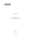
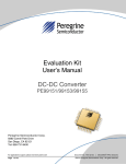
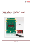
Evaluation Kit User’s Manual Digital Step Attenuator PE43704 Peregrine Semiconductor Corp. 9380 Carroll Park Drive San Diego, CA 92121 Tel: 858-731-9400 For applications support, please visit www.psemi.com Page 1 of 15 Document No. DOC-51949-1 │ UltraCMOS® RFIC Solutions ©2013 Peregrine Semiconductor Corp. All rights reserved. PE43704 Evaluation Kit Manual Table of Contents Introduction ………………………………………………………………………………….. 3 Applications Support ………………………………………………………………………. 3 Evaluation Kit Contents and Requirements …………………………………………… 3 Kit Contents …………………………………………………………...………………………… 3 Software Requirements ……………………………………………………….……………….. 3 Hardware Requirements ………………………………………………………………..……… 3 PE43704 DSA Evaluation Board Assembly ……………………….…………………… 4 Overview ………………………………………………………………………………...………. 4 USB Interface Board ………………………………………………………………….…….. 5 USB Interface Board Overview …………………………………………………..……………. 5 Connection of the USB Interface Board to the Evaluation Board …………………….…… 5 USB Driver Installation ………………………………………………………….……… 5 EVK Software Installation ………………………………………………………….……… 6 Using the Application Software Graphical User Interface ………….……………….. 9 Evaluation Board Overview ……………………………………………………….………. 12 Hardware Operation …………………………………………………………………….….. 14 Technical Resources ……………………………………………………………………….. 15 Document No. DOC-51949-1 │ www.psemi.com ©2013 Peregrine Semiconductor Corp. All rights reserved. For applications support, please visit www.psemi.com Page 2 of 15 PE43704 Evaluation Kit Manual Introduction PE43704 is a HaRP™ technology-enhanced, high linearity, 7-bit RF Digital Step Attenuator (DSA). This highly versatile DSA covers a 31.75 dB attenuation range in 0.25 dB, 0.5 dB, or 1.0 dB steps. The customer can choose which step size and associated specifications are best suited for their application. It provides multiple CMOS control interfaces which support direct-parallel, latch-parallel, and serial programming modes, and also has an optional external VSS feature. PE43704 maintains high attenuation accuracy over frequency and temperature, and exhibits low broadband insertion loss and low power consumption. Performance does not change with VDD due to an on-board regulator. This DSA is available in a 32-lead 5x5 mm QFN footprint. No blocking capacitors are required if DC voltage is not present on the RF ports. The PE43704 Evaluation Kit (EVK) includes the application software and hardware required to control and evaluate the functionality of the DSA using a PC running the Windows operating system to control the USB interface board. Applications Support For any technical inquiries regarding the evaluation kit or software, please visit applications support at www.psemi.com (fastest response) or call (858) 731‐9400. Evaluation Kit Contents & Requirements Kit Contents The PE43704 Evaluation Kit (EVK) includes all of the specific software and hardware required to evaluate the DSA. Included in the EVK are: Quantity Description 1 PE43704 DSA Evaluation Board Assembly (PRT-13505 ) 1 Peregrine USB Interface Board Assembly (102-0829) 1 USB 2.0 Micro B cable Software Requirements The application software will need to be installed on a computer with the following minimum requirements: PC compatible with Windows™ XP, Vista, 7, or 8 Mouse USB port HTML browser with internet access Hardware Requirements In order to evaluate the step attenuation performance of the evaluation board, the following equipment is required: DC power supplies and DC cables Vector network analyzer CAUTION: The PE43704 DSA EVK contains components that might be damaged by exposure to voltages in excess of the specified voltage, including voltages produced by electrostatic discharges. Handle the board in accordance with procedures for handling static-sensitive components. Avoid applying excessive voltages to the power supply terminals or signal inputs or outputs. For applications support, please visit www.psemi.com Page 3 of 15 Document No. DOC-51949-1 │ UltraCMOS® RFIC Solutions ©2013 Peregrine Semiconductor Corp. All rights reserved. PE43704 Evaluation Kit Manual PE43704 DSA Evaluation Board Assembly Overview The Evaluation Board is assembled with a PE43704 DSA, SP2T mechanical switch (P/S), SP3T mechanical switches (D0~D6), several headers, and SMA connectors. The P/S switch is used for parallel or serial mode selection. The D0~D6 switches are used for setting the control bits in direct-parallel programming mode. Figure 1. PE43704 Evaluation Board Assembly Document No. DOC-51949-1 │ www.psemi.com ©2013 Peregrine Semiconductor Corp. All rights reserved. For applications support, please visit www.psemi.com Page 4 of 15 PE43704 Evaluation Kit Manual USB Interface Board USB Interface Board Overview Figure 2. DSA USB Interface Board A USB interface board (Figure 2) is included in the Evaluation Kit. This board allows the user to send SPI commands to the device under test by using a PC running the Windows™ operating system. To install the software, extract the zip file to a temporary directory and follow the installation procedure included. Connection of the USB Interface Board to the Evaluation Board Figure 3. DSA USB Interface Board Connected to the PE43704 Evaluation Board for Latch-Parallel and Serial Programming The Evaluation Board and the USB interface board contain a keyed 16 pin header. This feature allows the USB interface board (socket) to connect directly to the Evaluation Board (pin) on the front-side as shown in Figure 3. USB Driver Installation Figure 4. USB Driver Installation The latest USB interface board drivers are available via Microsoft Windows update. Internet connectivity is required to download the drivers. Connect the USB interface board to the PC and select the Windows Update option to obtain and install the drivers. If the USB board drivers are not installed, it will not be possible to run the program correctly. A USB interface board (Figure 2) is included in the Evaluation Kit. For applications support, please visit www.psemi.com Page 5 of 15 Document No. DOC-51949-1 │ UltraCMOS® RFIC Solutions ©2013 Peregrine Semiconductor Corp. All rights reserved. PE43704 Evaluation Kit Manual EVK Software Installation In order to evaluate the PE43704 performance, the Application Software has to be installed on your computer. The USB interface and DSA application software is compatible with computers running Windows™ XP, Vista, 7, or 8. This software is available directly from Peregrine’s website at www.psemi.com. To install the DSA evaluation software, unzip the archive and execute the “setup.exe.” Figures 5(a-c). Application Software Installation Procedure After the “setup.exe” file has been executed, a welcome screen will appear. It is strongly recommended that all programs be closed prior to running the install program. Click the “Next>” button to proceed. Take a moment to read the license agreement, then click “I Agree” and “Next>.” Document No. DOC-51949-1 │ www.psemi.com ©2013 Peregrine Semiconductor Corp. All rights reserved. For applications support, please visit www.psemi.com Page 6 of 15 PE43704 Evaluation Kit Manual For most users the default install location for the program files is sufficient. If a different location is desired, the install program can be directed to place the program files in an alternate location. The software is installed for “Everyone” by default. Once the desired location is selected click “Next >.” Figures 5(d-f). Application Software Installation Procedure The “Confirm Installation” is ready to install the DSA evaluation software on your computer, then click “Next>” to proceed with the software installation. As the software files are installed, a progress indicator will be displayed. On slower computers, installation of the software may proceed for a few moments. For applications support, please visit www.psemi.com Page 7 of 15 Document No. DOC-51949-1 │ UltraCMOS® RFIC Solutions ©2013 Peregrine Semiconductor Corp. All rights reserved. PE43704 Evaluation Kit Manual Once the evaluation software is installed, click “Close” to exit. Figure 5(g). Application Software Installation Procedure A new Start Menu item under “Peregrine Semiconductor” will appear in the start menu of your computer. Select DSA Evaluation Software to launch the GUI. Document No. DOC-51949-1 │ www.psemi.com ©2013 Peregrine Semiconductor Corp. All rights reserved. For applications support, please visit www.psemi.com Page 8 of 15 PE43704 Evaluation Kit Manual Using the Application Software Graphical User Interface Figure 6 displays the DSA application software graphical user interface (GUI), which has the USB interface board plugged into the computer. If the USB interface board is not connected when the application software is launched, the message “No interface board connected! Please connect USB-SPI Interface #101-0695.” will appear at the bottom of the screen. In the upper left corner, under the Peregrine Logo there is a drop down menu item to select the part for evaluation and the part description is right below the part number box. Figure 6. DSA Application Software Graphical User Interface (GUI) For applications support, please visit www.psemi.com Page 9 of 15 Document No. DOC-51949-1 │ UltraCMOS® RFIC Solutions ©2013 Peregrine Semiconductor Corp. All rights reserved. PE43704 Evaluation Kit Manual The DSA application software GUI supports Latched-Parallel and Serial modes, and shows the control bit waveform at the right side of the GUI when the mode is selected. The Send button changes functionality based on the control interface mode. “Send Latch” in Latched-Parallel mode and “Send Signal” in Serial mode is provided to resend the programming bits to the device at the same attenuation state. Figure 7. Latched-Parallel or Serial Mode “Continuous Pattern Loop” can be selected to automatically step through each of the attenuation states. The “Attenuation Value” box displays the attenuation value the DSA is currently programmed. The user can enter the desired attenuation value followed by the ENTER key to program the DSA. Document No. DOC-51949-1 │ www.psemi.com ©2013 Peregrine Semiconductor Corp. All rights reserved. For applications support, please visit www.psemi.com Page 10 of 15 PE43704 Evaluation Kit Manual The center of the GUI is the attenuation slide bar that allows the user to quickly select the desired attenuation. The arrows at the top and bottom can be clicked to increase or decrease attenuation state at the minimum step size. For applications support, please visit www.psemi.com Page 11 of 15 Document No. DOC-51949-1 │ UltraCMOS® RFIC Solutions ©2013 Peregrine Semiconductor Corp. All rights reserved. PE43704 Evaluation Kit Manual Evaluation Board Overview Figure 8. PE43704 Evaluation Board Schematic J1 HEADER16 2 1 CO_25 4 3 C0_5 6 5 C1 8 7 C2 10 9 C4 12 11 C8CLK 14 13 C16/DATA 16 15 LE P/S VDD_DIG 5 D0 100pF C6 C4 100pF 100pF 100pF C2 C3 100pF HDR1 HEADER 1X2 4 C7 3 100pF 100pF 4 A2_1 A0_2 A0 VDD A1_1 A1_2 A1 VDD A0_1 A2_2 A2 VDD SI 25 GND 19 7 RF1 RF2 18 8 GND GND 17 2 D3 VSS VDD_DIG C9 0.1µF C11 VDD HDR2 3 4 100pF 3 Z=50 Ohm 1 2 HEADER_4 D4 C10 100pF 1 2 3 4 1 2 J5 142-0761-881/891 4 1 D5 6 GND 16 GND DSA_50OHM_5X5_MLPQ32 VSS 20 1 4 2 C8 27 C16 26 C4 28 A2 21 5 GND 9 GND 2 1 U1 4 A0 15 GND J4 Z=50 Ohm 142-0761-881/891 A1 22 14 GND C8 0.1µF 3 PS 13 GND C12 100pF LE 23 3 HEADER3X3 CLK 24 2 VDD 12 GND VDD C2 29 1 GND 0 OHM DNI C1 30 R2 11 GND 2 2 CP25 32 R1 10 GND 1 1 CP5 31 2 DNI D2 HDR4 2 2 1 2 VDD_DIG 1 1 1 1 2 D1 C1 HDR3 HEADER 1X2 6 3 C5 4 3 1 2 4 DNI R3 1 D6 2 3 1 2 4 De-embeding trac e J10 J11 Z=50 Ohm 142-0761-881/891 142-0761-881/891 1 2 2 1 R4 0 OHM DOC-06527 NOTES: 1. USE PRT-13505-01 PCB. 2. CAUTION: CONTAINS PARTS AND ASSE MBLIES SUSCEPTIBLE TO DAMAGE BY ELECTROSTATIC DISCHARGE (ESD) Document No. DOC-51949-1 │ www.psemi.com ©2013 Peregrine Semiconductor Corp. All rights reserved. For applications support, please visit www.psemi.com Page 12 of 15 PE43704 Evaluation Kit Manual Figure 9. PE43704 Evaluation Board Outline Showing Functional Overview USB interface board connector “High” in direct-parallel mode Programming switches Set for latched-parallel/serial mode “Low” in direct-parallel mode Set to “high” A2 A1 A0 Jumper connected Power supply connector RF in/out Set to “low” Parallel/serial mode selection RF in/out “THRU” trace is for board trace loss calibration For applications support, please visit www.psemi.com Page 13 of 15 Document No. DOC-51949-1 │ UltraCMOS® RFIC Solutions ©2013 Peregrine Semiconductor Corp. All rights reserved. PE43704 Evaluation Kit Manual Hardware Operation 1. Verify that all DC power supplies are turned off before proceeding. 2. Connect the jumper on HDR1. 3. Position the “P/S” switch to Parallel or Serial mode. 4. Set A0, A1, and A2 to “LOW” on HDR4 for default setting. They can be set to “HIGH” or “LOW” for Serial Addressable mode when more of the DSAs are used. Refer to Application Note AN26 on Peregrine Semiconductor’s website. 5. Set the D0~D6 programming switches to support Direct-Parallel, Latched-Parallel, or Serial mode. a) Place D0~D6 at the middle position to support Latched-Parallel and Serial modes with GUI application software and proper position of the P/S switch. b) In Direct-Parallel mode, D0~D6 can be set to “HIGH” or “LOW” to manually program the attenuation state while LE (pin 15 of J1) is connected to “HIGH” without using the USB interface board and application software. 6. Provide external power supply to the HRD2 connector. a) VDD is the PE43704 positive power supply. b) VDD_DIG is the positive power supply for control signals, and it can be provided with VDD to simplify the test set-up. c) VSS is the external negative power supply for PE43704. It can also be shorted to GND for PE43704 using the internal negative voltage generator and simplify the test set-up. 7. Calibrate board trace loss with “THRU” trace between J10 and J11. Document No. DOC-51949-1 │ www.psemi.com ©2013 Peregrine Semiconductor Corp. All rights reserved. For applications support, please visit www.psemi.com Page 14 of 15 PE43704 Evaluation Kit Manual Technical Resources Additional technical resources are available for download in the Products section at www.psemi.com. These include the Product Specification datasheet, S-Parameters zip file, Evaluation Kit schematic and Bill of Materials, Material Declaration form, and PC-compatible software file. The information in this document is believed to be reliable. However, Peregrine assumes no liability for the use of this information. Use shall be entirely at the user’s own risk. No patent rights or licenses to any circuits described in this document are implied or granted to any third party. Peregrine’s products are not designed or intended for use in devices or systems intended for surgical implant, or in other applications intended to support or sustain life, or in any application in which the failure of the Peregrine product could create a situation in which personal injury or death might occur. Peregrine assumes no liability for damages, including consequential or incidental damages, arising out of the use of its products in such applications. The Peregrine name, logo, UltraCMOS and UTSi are registered trademarks and HaRP, MultiSwitch and DuNE are trademarks of Peregrine Semiconductor Corp. All other trademarks mentioned herein are the property of their respective companies. Peregrine products are protected under one or more of the following U.S. Patents: http:patents.psemi.com For applications support, please visit www.psemi.com Page 15 of 15 Document No. DOC-51949-1 │ UltraCMOS® RFIC Solutions ©2013 Peregrine Semiconductor Corp. All rights reserved.